Advertisement
Quick Links
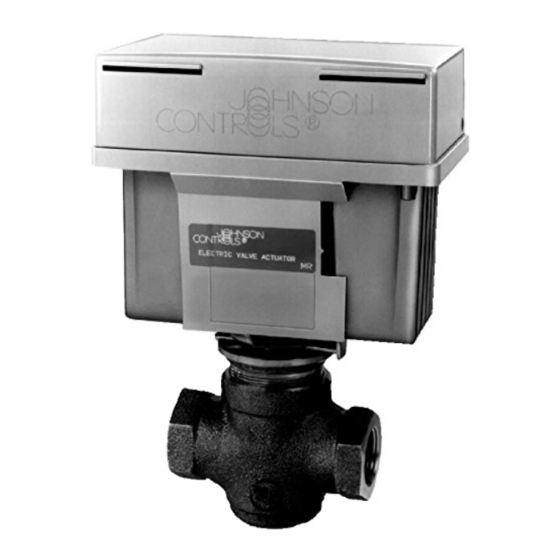
The VA-8052-1 motor-driven
actuator provides proportional
control of valves with up to
3/4 in. lift in heating, ventilating,
and air conditioning
applications. This non-spring
return actuator has a 50 lb force
and requires a two-wire, voltage
signal (usually 0 to 10 VDC)
from the controller, and 24 VAC
power.
Installation
!
WARNING: Equipment
Damage Hazard. Do not
drive the VA-8052 actuator
unless it is mounted to a
valve. This can result in
permanent damage to the
actuator.
Installation of VA-8052-1 on
1/4 in. and 1/2 in. Stroke Valves
1.
Unpack the VA-8052
Actuator and insure that the
feedback potentiometer
plunger is on top of the
coupler arm.
2.
Install the valve packing
that is provided according
to the instructions included
with it.
3.
Thread the 1/4 in. Palnut,
open side down, all the way
onto the valve stem.
4.
Loosely install the actuator
by sliding the actuator yoke
between the spring plate
and valve centerpiece
surface. Finger tighten the
spring plate to hold the
actuator in place (see
Fig. 1).
5.
Obtain a source of 24 VAC
power and wire to the AC
and COM terminals. Wire a
source of 0 to 10 VDC to
the IN and COM terminals
(see Fig. 4). Check to see
© 1989 Johnson Controls, Inc.
Part No. 14-761-0, Rev. --
Code No. LIT-977310x
Actuators and Positioners Product Information Section
VA-8052 Electric Valve Actuator
Installation & Calibration
that the stroke
potentiometer is fully CCW
(see Fig. 1).
6.
Thread the knurled coupler
onto the valve stem until
approximately 1/4 in. of
thread remains between the
knurled coupler and the
Palnut. Note: It may be
necessary to pull the valve
stem up to meet the coupler
or to apply 0 to 10 VDC to
position the coupler above
the valve stem.
7.
Secure the actuator in place
by tightening the spring
plate with a large
screwdriver (see Fig. 2).
8.
Stroke the actuator to the
stem-up position by
applying 0 VDC. Thread
the knurled coupler onto the
valve stem until the knurled
coupler fits snugly.
9.
Increase the signal slightly
(to 3 to 4 VDC) so that tension
on the coupler is relieved.
When lever stops moving,
thread the knurled coupler
on another 1 to 1-1/4 turn.
Valve and Actuator Manual 977
Technical Bulletin VA-8052
Issue Date 0489
10. Reduce the signal to zero to
stroke the actuator to the
stem-up position. The limit
switch should click softly at
the full stem-up position. If
not, repeat step 9.
11. With the valve driven fully
up, thread the Palnut up the
stem until it contacts the
coupler. Tighten the Palnut
with a 7/16 in. wrench while
holding the nut on top of the
coupler with a 1/2 in.
wrench.
12. Provide an input signal of
10 VDC to the actuator.
After the actuator strokes
completely to the stem-
down position, slowly adjust
the stroke potentiometer
CW until the stem just
begins to move up. Then
adjust the stroke
potentiometer CCW until
the stem strokes down and
the limit switch clicks. Turn
the stroke adjustment an
additional 1/8 rotation CCW
to assure positive full
stroke.
1
Advertisement

Subscribe to Our Youtube Channel
Related Manuals for Johnson Controls VA-8052


Summary of Contents for Johnson Controls VA-8052
- Page 1 Valve and Actuator Manual 977 Actuators and Positioners Product Information Section Technical Bulletin VA-8052 Issue Date 0489 VA-8052 Electric Valve Actuator Installation & Calibration The VA-8052-1 motor-driven actuator provides proportional control of valves with up to 3/4 in. lift in heating, ventilating, and air conditioning applications.
- Page 2 (see Fig. 2: Isometric Drawing of VA-8052 Fig. 1). Installation of VA-8052-1 on 3/4 in. Stroke, 2-Way Push Down to Open (PDO) Valves 1 .
- Page 3 (see Fig. 1). Installation of VA-8052-1 on 3/4 in. Stroke 2-Way, Push Down to Close (PDC) Valves Unpack the VA-8052 Actuator and insure that the...
- Page 4 The stroke, zero, and span Adjust the stroke switch clicks. Note: The settings are factory calibrated to potentiometer fully CCW to lever plate must not contact accept a 0 to 10 volt signal from maximum. Adjust the span 4 VA-8052 Technical Bulletin...
- Page 5 Identification stroke. Fig. 4 -- Typical Application must be at least 2.5 VDC greater than the zero value.) Fig. 5 -- VA-8052 Dimensions in./mm Controls Group 507 E. Michigan Street P.O. Box 423 Printed in U.S.A. Milwaukee, WI 53202 VA-8052 Technical Bulletin...
Need help?
Do you have a question about the VA-8052 and is the answer not in the manual?
Questions and answers