Table of Contents
Advertisement
Advertisement
Table of Contents

Related Manuals for Audio Precision 2700 Series


Summary of Contents for Audio Precision 2700 Series
- Page 1 2700 Series Getting Started with Your 2700 Series Instrument...
- Page 3 Getting Started with Your 2700 Series Instrument An Introductory Guide to • SYS-2722 • and • SYS-2720 • SYS-2712 • SYS-2702 • with AP2700 3.30 SP1 APIB and GPIB Configurations...
- Page 4 2003–2013 Audio Precision, Inc. All rights reserved. Part Number 8211.0184 Revision 9 All content in this manual is owned by Audio Precision and is protected by United States and international copyright laws. Audio Precision allows its customers to make a limited number...
-
Page 5: Table Of Contents
GPIB........2 2700 Series Capabilities ......2 About This Manual . - Page 6 The Workspace....... 21 The 2700 series panels......22 Panel Settings .
- Page 7 Establishing GPIB Communication....96 GPIB Connection ......96 Getting Started with Your 2700 Series Instrument...
- Page 8 GPIB Status LEDs ......98 GPIB Program Message Terminators ....98 Getting Started with Your 2700 Series Instrument...
-
Page 9: Safety Information
Au dio Pre ci sion. Doing so may cre ate safety haz ards. This prod uct is for in door use—In stal la tion Cat e gory II, Mea sure ment Cat e gory I, pol lu tion de gree 2 Getting Started with Your 2700 Series Instrument... -
Page 10: Safety Symbols
Au dio Pre ci sion cau tions against us ing their prod ucts in a man ner not spec i - fied by the man u fac turer. To do oth er wise may void any war ran ties, dam age equip ment, or pose a safety risk to per son nel. Getting Started with Your 2700 Series Instrument... -
Page 11: Chapter 1 General Information
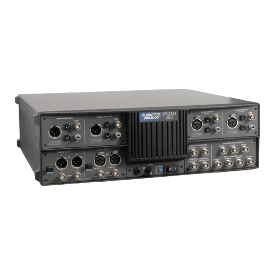
Chapter 1 General Information Figure 1. The Audio Precision 2700 series audio test and measurement instrument; SYS-2722 shown. The 2700 Series: an Overview Au dio Pre ci sion 2700 se ries in stru ments are com puter-controlled au dio test sets of fer ing broad, high-performance ca pa bil i ties for test ing an a log, dig i tal, and mixed-domain de vices. -
Page 12: Apib
The an a log gen er a tor and an a lyzer have a num ber of hard ware op tions that can be added to en hance the in stru ment’s ca pa bil ity, in clud ing plug-in fil ters, Getting Started with Your 2700 Series Instrument... -
Page 13: About This Manual
The fol low ing list de scribes the doc u ments that are in cluded as Adobe Ac ro bat PDF files on the Re sources CD-ROM that is included with your in stru ment. They can also be down loaded from our Web site at ap.com. Getting Started with Your 2700 Series Instrument... -
Page 14: 2700 Se Ries User's Man Ual
In for ma tion about out li brary of tech ni cal pa pers and an nounce - ments of new pa pers is avail able on the Au dio Pre ci sion Web site at ap.com. Getting Started with Your 2700 Series Instrument... -
Page 15: Gpib Documentation For The 2700 Series
GPIB de vel op ment and pro gram ming, or der the 2700 Se ries GPIB Pro gram - mer’s Ref er ence Man ual, which in cludes a CD-ROM with GPIB sam ple pro - gram files. Getting Started with Your 2700 Series Instrument... - Page 16 Chapter 1: General Information Other 2700 Series Documentation Getting Started with Your 2700 Series Instrument...
-
Page 17: Installation And Setup For Apib
The fol low ing items are in cluded with a stan dard, APIB-con fig ured 2700 se ries in stru ment. For a GPIB-con fig ured in stru ment, re fer to Chap ter 7. The 2700 series in stru ment chas sis. A mains power cord. -
Page 18: Getting Up And Run Ning
You must have at least 300 MB of free hard disk space. You must have CD-ROM drive. for op er a tion us ing a 64-bit OS: You must have a USB 2.0 port, and use the Au dio Pre ci sion USB-APIB adapter. Getting Started with Your 2700 Series Instrument... -
Page 19: In Stalling The Soft Ware
Start menu and choose Run. Click Browse and choose the file Setup.exe on the AP2700 CD-ROM. Click OK in the Run di a log box. Fol low the in staller on-screen in struc tions. Getting Started with Your 2700 Series Instrument... -
Page 20: Set Ting Up The Hard Ware
Figure 2. Detail, power entry module on 2700 series instrument rear panel. Getting Started with Your 2700 Series Instrument... -
Page 21: Changing The Mains Supply Voltage Configuration
Power En - try Mod ule as shown in Fig ure 4. Pull the volt age se lec tor card straight Getting Started with Your 2700 Series Instrument... - Page 22 Close the mod ule the cover door and ver ify that the in di ca tor pin shows the de sired volt age. 100V 120V 230V 240V 90° 90° 90° Figure 5. Voltage card selector orientation. Getting Started with Your 2700 Series Instrument...
-
Page 23: Fuse Information
Once you have ver i fied that the line volt age se lec tion is cor rect, con nect the power cord from a mains power out let to the power cord con nec tor on the in - stru ment rear panel. Getting Started with Your 2700 Series Instrument... -
Page 24: Connecting The Instrument To Your Pc
PC USB 2.0 port, and that you do not use a USB hub for this con nec tion. USB 1.0 or 1.1 ports or hubs can not be used. Getting Started with Your 2700 Series Instrument... -
Page 25: The Apib Pci Express Card And Ca Ble
Express slots, and that you may dam age the card and your PC by forc ing an in ter face card into the wrong slot. Turn on the PC and the in stru ment, and launch AP2700. Getting Started with Your 2700 Series Instrument... -
Page 26: The Apib Pcmcia Card And Ca Ble
OPT-2711 Dolby Dig i tal Gen er a tor op tion. * Dolby and the dou ble-D sym bol are trade marks of Dolby Lab o ra to ries. Getting Started with Your 2700 Series Instrument... -
Page 27: Chapter 3 Hardware Overview
Analog Outputs Analog Inputs Digital Output Digital Input Headphone Jack Mains Power Sync and Trigger Signal Monitor Switch Ports Ports Volume Control Figure 11. SYS-2722 front panel. Getting Started with Your 2700 Series Instrument... - Page 28 POWER SWITCH and INDICATOR The power switch turns the mains power sup ply to the in stru ment hard - ware ON ( I ) or OFF ( O ). Getting Started with Your 2700 Series Instrument...
-
Page 29: The 2700 Series Rear Panel
See Chapter 2. SYNC and REFERENCE OUTPUTS AES/EBU Reference Master Clock Out Transmitter Frame Sync Out Receiver Frame Sync Out Getting Started with Your 2700 Series Instrument... - Page 30 See Chap ters 4 and 24 of the 2700 Se ries User’s Man ual for more in for ma - tion about the in stru ment rear panel par al lel dig i tal and sync and ref er ence in - puts and out puts. Getting Started with Your 2700 Series Instrument...
-
Page 31: 2700 Series Control Software
2700 Series Control Software Overview Most of your in ter ac tion with your 2700 series in stru ment will be through the con trol soft ware, AP2700. Once the sys tem is plugged in, turned on and con nected to your de vice un der test (or DUT), you will be mak ing all your ad - just ments and tak ing all your read ings from your com puter screen. -
Page 32: The 2700 Series Panels
A more typ i cal test might in - volve four or five pan els; a com pli cated test, per haps six or seven. Getting Started with Your 2700 Series Instrument... -
Page 33: Panel Settings
Set ting fields, which come in sev eral ver sions: The text box, in which you can directly enter a value from the keyboard. The drop-down list box, in which you can make a selection from a set of choices. Getting Started with Your 2700 Series Instrument... -
Page 34: Panel Readings
Sta tus in di ca tors, which show the pres ence or ab sence of a con di tion by a small col ored rect an gle. Getting Started with Your 2700 Series Instrument... -
Page 35: The 2700 Se Ries Menus
The list ings at the bot tom of the File menu show the last tests opened by the 2700 series, and pro vide a con ve nient way to quickly launch a pre vi ously used test. Sim ply click on the name of the test you would like to open. -
Page 36: The Edit Menu
See the user’s man ual for more in for ma tion about us ing the Data Ed i tor. Getting Started with Your 2700 Series Instrument... -
Page 37: The View Menu
A checkmark next to a View menu list ing in di cates that the se lec tion is vis i ble. You can also open the At tached Files viewer from the View menu. Go the user’s man ual for more in for ma tion about the At tached Files viewer. Getting Started with Your 2700 Series Instrument... -
Page 38: The Panels Menu
The panel func tions are dis cussed in de tail in the 2700 Se ries User’s Man - ual. Getting Started with Your 2700 Series Instrument... -
Page 39: The Status Bar
The Macro toolbar of fers one-click op er a tions for run ning and ed it ing an AP Ba sic macro. See the 2700 Se ries User’s Man ual for de tailed in for ma tion. Getting Started with Your 2700 Series Instrument... -
Page 40: The Learn Mode Toolbar
Launch to open the Quick Launch Con fig u ra tion panel, where you can view or edit the ex ist ing Quick Launch com mands or to add new com mands of your own. Figure 15. The Quick Launch Configuration panel. Getting Started with Your 2700 Series Instrument... - Page 41 Au to matically run when loaded. To open the test, macro or pro gram, click the but ton on the Quick Launch toolbar. See the 2700 Se ries User’s Man ual for de tailed in for ma tion. Getting Started with Your 2700 Series Instrument...
- Page 42 Chapter 4: 2700 Series Control Software The 2700 se ries menus Audio Precision 2700 Series User’s Manual...
-
Page 43: Chapter 5 Quick Guides
Quick Guides Introduction Figure 16. 2700 series workspace, New Test defaults. The Quick Guides in this chap ter pro vide a way to get fa mil iar with the 2700 se ries user in ter face, and to get some im me di ate re sults from your in stru - ment. -
Page 44: The Analog Signal Path
An a log An a lyzer or by click ing the An a log An a lyzer but ton. Choose GenMon for each chan nel to se lect the in ter nal path. Analog Generator Panel Figure 18. Analog Generator, OUTPUTS ON, CHB OFF. Getting Started with Your 2700 Series Instrument... -
Page 45: Using The Analog Analyzer
At this point, you should have the setup shown in Fig ure 19: An a log Gen er a tor Chan nel A pro duc ing a 1 V, 1 kHz sine wave. Getting Started with Your 2700 Series Instrument... -
Page 46: Audible Signal Monitor
A sig nal. The speaker level will drop by about half, since it is now re pro duc ing only the chan nel B sig nal. Click CHA ON again, and the sound will get louder. Getting Started with Your 2700 Series Instrument... -
Page 47: Controlling The Analog Generator
The am pli tude for each chan nel is con trolled by fields be low the OUTPUTS field. If the Track A checkbox is checked, the Getting Started with Your 2700 Series Instrument... -
Page 48: Units
An a log Gen er a tor or An a log An a lyzer panels. Re fer to Ap pen dix A of the 2700 Se ries User’s Man ual for more in for ma tion about units of mea sure ment. Getting Started with Your 2700 Series Instrument... -
Page 49: Sweeps
Chapter 5: Quick Guides Sweeps Most de vice test ing with the 2700 series is per formed us ing sweeps. In a sweep, a set ting is stepped over a pre-defined range, while se lected read ings are gath ered. The re sult is a ta ble of data re lat ing the read ings to each value of the set ting. -
Page 50: Sweep Fundamentals
Freq from the set ting side, the fre quency of the An a log Gen er a - tor will be var ied dur ing the sweep. This is shown in the Source 1 field as Gen.Freq. Getting Started with Your 2700 Series Instrument... -
Page 51: Source Range, Steps, And Spacing
On the other hand, if the Spacing is lin ear, the gen er a tor is first set to 20 Hz, then 6680 Hz, then 13340 Hz, and fi nally 20 kHz; that is, the dif fer ence be - tween suc ces sive fre quency set tings is 6660 Hz. Getting Started with Your 2700 Series Instrument... -
Page 52: Data Display Range
The de fault range for Data 1 is quite wide, and the units are Volts. Change the units to dBV by click ing on the ar row next to the Top field. From the list, choose the dBV line. (Note that the units in the Bot tom Getting Started with Your 2700 Series Instrument... -
Page 53: Example Sweep: Amplitude Linearity
First, click New Test, turn the An a log Gen er a tor ON, and set the An a log An a lyzer Source A and B to GenMon so that the gen er a tor sig nal is sent di - Getting Started with Your 2700 Series Instrument... - Page 54 The re sult will be a curve that de vi ates only slightly from 0 dBg A, as shown in Fig ure 26. Figure 26. Current workspace after amplitude linearity sweep, showing typical results. Getting Started with Your 2700 Series Instrument...
-
Page 55: Dsp Analysis
(spec trum an a lyzer-style). It op er ates in a dif fer ent fash ion from the An a log An a lyzer, as ex plained next. Getting Started with Your 2700 Series Instrument... -
Page 56: Real-Time Vs. Batch-Mode Instruments
Win dow ing. Be fore trans for ma tion, the au dio data is shaped in time by mul ti ply ing it with a pre-defined en ve lope. This in creases the ac cu racy of the am pli tude val ues re turned from the FFT. Getting Started with Your 2700 Series Instrument... -
Page 57: Setting Up An Fft
The choice of do main is de ter mined by the Source 1 field on the Sweep panel. If it is set to Fft.FFT Time, a time Getting Started with Your 2700 Series Instrument... -
Page 58: Quick Sweep Setup
Wave form but ton again. Source 1 changes to Fft.FFT Time and the graph up dates to show the new data. You should see a graph sim i lar to Fig ure 30. Getting Started with Your 2700 Series Instrument... -
Page 59: Fine-Tuning The Display
From the right-click menu, choose Op ti mize Left Only. The ver ti cal axis changes to best fit the data in the graph. For more de tails, see Chap ter 18 of the 2700 Se ries User’s Man ual. Getting Started with Your 2700 Series Instrument... -
Page 60: Saving And Loading Tests
AP Ba sic Man ual de scribes the lan guage in de tail, and the AP Ba sic Ex ten sions Ref er ence for the 2700 Se ries Instruments de tails the spe cific com mands for this se ries. Getting Started with Your 2700 Series Instrument... -
Page 61: Chapter 6 Specifications
Chapter 6 Specifications Analog Signal Outputs All 2700 series configurations except SYS-2720 contain an ultra-low distortion analog sine wave generator and two independent transformer-coupled output stages. The SYS-2712 and SYS-2722 configurations also contain a dual-channel D/A signal generator for enhanced capabilities. Option “BUR” adds analog-generated sine burst, square wave, and noise signals. - Page 62 20 Hz–50 kHz only. Decrease maximum output by a factor of 2 (–6.02 dB) for the full 10 Hz–204 kHz range. System specification measured with the 2700 series analog analyzer set to the indicated measurement bandwidth (BW). Generator amplitude setting must be...
- Page 63 Frequency Range 20 Hz–20 kHz. Frequency Accuracy Same as Sinewave. Amplitude Range Balanced 30 µVpp–37.7 Vpp. Unbalanced 30 µVpp–18.8 Vpp. Amplitude Accuracy ±2.0% [±0.17 dB] at 400 Hz. Rise/fall time Typically 2.0 µs. Getting Started with Your 2700 Series Instrument...
- Page 64 -140 Rate = 262 ks/s, 16 -150 averages). -160 100k 110k 120k Figure 35. Typical analog system flatness at 2 Vrms signal level (measured with the analog analyzer’s Level meter, dc input coupling). Getting Started with Your 2700 Series Instrument...
-
Page 65: D/A Generated Analog Signals
Significant generator alias products will appear for frequency settings above 29.5 kHz in the ‘30k’ range and 53.5 kHz in the ‘60k’ range. System specification measured with the 2700 series analog analyzer set for a 22 kHz measurement BW. Getting Started with Your 2700 Series Instrument... - Page 66 Passes the embedded audio signal from the rear panel Reference Input. Ratio of reference rate to output Sample Rate may not exceed 8:1. System specification measured with the 2700 series analog analyzer at any voltage 200 mVrms. Getting Started with Your 2700 Series Instrument...
- Page 67 D/A Generated Analog Signals Chapter 6: Specifications Squarewave Frequency Range 20 Hz–20.0 kHz. Rise Time Typically 2.0 µs. Noise Signal Pseudo-random white Getting Started with Your 2700 Series Instrument...
-
Page 68: Analog Analyzer
Analog Analyzer Analog Analyzer All 2700 series configurations except SYS-2720 contain an input module with two independent auto-ranging input stages, each having its own level (rms) and frequency meters; a phase meter; plus a single channel multi-function analyzer module providing additional signal processing and gain stages. - Page 69 0.02 dB in the 20 V, 40 V, 80 V, and 160 V input ranges. Both analyzer input channels must have same coupling (ac or dc) selection. Accuracy is valid for any input signal amplitude ratio up to 30 dB. Getting Started with Your 2700 Series Instrument...
- Page 70 ±2%. Bandreject Response typically –3 dB at 0.73 f & 1.37 f –20 dB at f ±10%, –40 dB at f ±2.5%. Accuracy ±0.3 dB, 20 Hz–120 kHz (excluding 0.5 f –2.0 f Getting Started with Your 2700 Series Instrument...
- Page 71 Amplitude modulation products of the HF tone. –3 dB measurement bandwidth is typically 20 Hz–750 Hz. System specification measured with the 2700 series analog generator and the analog analyzer set to the indicated measurement bandwidth (BW). Generator amplitude setting must be 12 Vrms balanced or 6 Vrms unbalanced for specified system performance below 30 Hz.
- Page 72 System specification measured with the 2700 series analog generator at any valid input level 200 mVrms. IEC 268-3 defines nine possible DIM products. The 2700 series IMD option analyzer is sensitive only to the u4 and u5 products using the simplified measurement technique proposed by Paul Skritek. DIM measurements using this technique will typically be 6 dB–8 dB lower (better) than the results obtained using FFT-based...
- Page 73 Settling Time IEC/DIN or NAB Typically 3 seconds–6 seconds. Typically 15 seconds–20 seconds. Operational only with high-band test signals (11.5 kHz–13.5 kHz). Upper –3 dB rolloff is typically 4.5 kHz using 12.5 kHz. Getting Started with Your 2700 Series Instrument...
-
Page 74: Option Filters
Only one option filter may be enabled at a time, and it is cascaded with the standard bandwidth limiting filters. The following tables list only the most popular types. Consult Audio Precision for custom designs. Weighted Noise Measurement FIL-AWT “A”... - Page 75 (FM) notch De-emphasis Filter. Figure 44. FIL-D75. 75 µs De-emphasis Figure 45. FIL-D75B. 75 µs with 15.734 Filter. kHz (NTSC) notch De-emphasis Filter. Figure 46. FIL-D75F. 75 µs with 19 kHz (FM) notch De-emphasis Filter. Getting Started with Your 2700 Series Instrument...
- Page 76 Figure 49. 8 kHz 7-pole Low Pass Filter. General Purpose High-Pass FHP-70 70 Hz 3%, 8-pole. FHP-400 400 Hz 3%, 9-pole. –see Figure 50 FHP-2K 2 kHz 3%, 9-pole. Figure 50. FHP- 400. 400 Hz 9- pole High Pass Filter. Getting Started with Your 2700 Series Instrument...
- Page 77 = 8.00 kHz. FBP-10000 = 10.0 kHz. FBP-12500 = 12.5 kHz. FBP-15000 = 15.0 kHz. FBP-20000 = 20.0 kHz. FBP-30000 = 30.0 kHz. Figure 51. FBP-xxxx. Normalized Response of 1/3- Octave Band Pass Filters Getting Started with Your 2700 Series Instrument...
- Page 78 FBP-500X High-Q 500 Hz bandpass for CD DAC linearity measurements. –see Figure 54 FIL-USR Kit for building custom filters. Figure 54. FBP-500X. High- Q 500 Hz Band Pass Filter (for CD linearity testing). Getting Started with Your 2700 Series Instrument...
-
Page 79: Option S-Aes17
100k 200k Figure 55. Typical response of 20 kHz “pre-analyzer” filter. Residual THD+N (1 kHz) “20k AES17” mode (0.00030% + 1.0 µV) [–110.5 dB]. “40k AES17” mode (0.00040% + 1.4 µV) [–108 dB]. Getting Started with Your 2700 Series Instrument... -
Page 80: Dsp Analysis Of Analog Signals
Normal, Interpolate, Peak or Max. Frequency Domain Peak pick (highest bin amplitude is displayed between the requested graph points). Frequency Display Modes Peak pick, individual bin. Alias rejection is provided by digital filters within the A/D converters. Getting Started with Your 2700 Series Instrument... - Page 81 CCIR QPk per IEC468 (CCIR), CCIR RMS per AES17, C-message per IEEE Std 743-1978, CCITT per CCITT Rec. O.41, “F” weighting corresponding to 15 phon loudness contour, –see Figure 58 HI-2 Harmonic weighting. Getting Started with Your 2700 Series Instrument...
- Page 82 CCIR QPk per IEC468 (CCIR), CCIR RMS per AES17, C-message per IEEE Std 743-1978, CCITT per CCITT Rec. O.41, “F” weighting corresponding to 15 phon loudness contour, –see Figure 29 HI-2 Harmonic weighting. Getting Started with Your 2700 Series Instrument...
- Page 83 (ac or dc) selection. Accuracy is valid for any input signal amplitude ratio up to ±30 dB. Upper frequency range limited to 45% of Sample Rate. System specification measured with the 2700 series analog generator. Valid for input levels 200 mVrms.
- Page 84 Noise vs frequency, Phase vs frequency, Crosstalk vs frequency, Masking curve. Frequency Resolution (Sample Rate Transform Length) [1.465 Hz with f = 48 ks/s & Transform Length = 32768]. Frequency Correction Range Distortion –115 dB. Getting Started with Your 2700 Series Instrument...
-
Page 85: Digital Signal Generator
Chapter 6: Specifications Digital Signal Generator Available only in the SYS-2720 and SYS-2722 configurations. The 2700 series digital generator consists of a DSP signal generator, hardware impairment generators and processing (for example, variable risetime and induced jitter), and digital output stages supporting the most popular formats. - Page 86 1.5 Vpp (AES/EBU) or 300 mVpp (SPDIF-EIAJ) and have a risetime 20 ns. Jitter via the optical path may be considerably worse with embedded audio or dither enabled (limited by Toslink® technology). Getting Started with Your 2700 Series Instrument...
- Page 87 Upper Tone Range 2 kHz to 47% of Sample Rate [22.56 kHz at 48 ks/s]. Lower Tone Range 40 Hz–500 Hz. Amplitude Ratio 1:1 or 4:1 (LF:HF). Distortion/Spurious 0.000001% [–160 dB] at 4:1 ratio. Getting Started with Your 2700 Series Instrument...
- Page 88 Walking Ones A single binary one value “walked” from LSB to MSB. Walking Zeros A single binary zero value “walked” from LSB to MSB. Constant Value (Digital dc) 32-bit resolution when using triangular dither. Getting Started with Your 2700 Series Instrument...
- Page 89 Flat (white) or Shaped (+6 dB/oct). Amplitude 8 bit–24 bit, or OFF. Pre-Emphasis Filters (all waveforms) Filter Shape 50/15 µs or J17. Response Accuracy 0.02 dB, 10 Hz to 45% of Sample Rate. Residual Distortion 0.00003% [–130 dB]. Getting Started with Your 2700 Series Instrument...
-
Page 90: Digital Analyzer
1.5 Vpp (AES/EBU) or 300 mVpp (SPDIF-EIAJ) and have a risetime 20 ns. Jitter via the optical path may be considerably worse with embedded audio or dither enabled (limited by Toslink® technology). Getting Started with Your 2700 Series Instrument... -
Page 91: Digital Interface Analyzer
10 Hz to 45.8% of Sample Rate, [10 Hz–20.2 kHz at 44.1 ks/s], [10 Hz–22.0 kHz at 48 ks/s], [10 Hz–44.0 kHz at 96 ks/s]. Accuracy 0.01 dB. Flatness 0.01 dB, 15 Hz–22 kHz (<10 Hz high-pass filter selection). Getting Started with Your 2700 Series Instrument... - Page 92 Residual Noise Same as Wideband Level/Amplitude. Frequency Measurements Range 10 Hz to 47% of Sample Rate, [10 Hz–21.0 kHz at 44.1 ks/s], [10 Hz–23.0 kHz at 48 ks/s], [10 Hz–46.0 kHz at 96 ks/s]. Getting Started with Your 2700 Series Instrument...
- Page 93 ±30 dB. Both DSP analyzer input channels must have same coupling (ac or dc) selection. Accuracy is valid for any input signal amplitude ratio up to ±30 dB Getting Started with Your 2700 Series Instrument...
- Page 94 Hann, <240 Hz >8 kHz, <120 Hz >16 kHz. Time Windows <5%, (percent of data record to <10%, transition from 0 to full <20%, amplitude) <30%. Averaging 1–4096 averages in binary steps, synchronous. Getting Started with Your 2700 Series Instrument...
-
Page 95: Graphs Of Typical Digital Domain Performance
Figure 61. Typical Digital Domain system residual THD+N showing components below –140 dB. Figure 62. Illustration of typical Digital Domain FFT dynamic range. Signal is 0 dB 1 kHz with a secondary signal at –120 dB and 2.5 kHz. Getting Started with Your 2700 Series Instrument... -
Page 96: Front Panel Auxiliary Signals
Buffered ver sion of the dig i tal chan nel 2 sig nal. Read ing 1 Dis tor tion of the dig i tal chan nel 1 sig nal. Read ing 2 Dis tor tion of the dig i tal chan nel 2 sig nal. Getting Started with Your 2700 Series Instrument... -
Page 97: Rear Panel Auxiliary Signals
Type “Grade 2 ref er ence,” Or i gin “SYS2,” Reliability flags im ple mented, CRCC im ple mented, Time of Day not im ple mented, Sam ple Count not im ple mented. Getting Started with Your 2700 Series Instrument... -
Page 98: Miscellaneous Digital I/O
HCMOS sig nal, co in ci dent with pe riod of gen er ated sig nal wave form. Par al lel In put and Out put For use with op tional PSIA-2722 accessory. Getting Started with Your 2700 Series Instrument... -
Page 99: General/Environmental
XLR-type con nec tors, Au dio Pre ci sion pn 4155.0301 ca ble for the Mas ter Clk port, and Pasternack Model No. PE3067-36 for all remaining ports using BNC-type connectors. Getting Started with Your 2700 Series Instrument... - Page 100 Chapter 6: Specifications General/Environmental Getting Started with Your 2700 Series Instrument...
-
Page 101: Gpib Configuration
PARALLEL OUTPUT PARALLEL INPUT Mains Power Entry Sync and Reference Parallel Digital Input APSI Fusing and Voltage Inputs and Outputs and Output port Configuration Figure 65. Rear panel, 2700 series instrument with GPIB Option. Getting Started with Your 2700 Series Instrument... -
Page 102: Apib Or Gpib
GPIB soft ware for it. Fig ure 66 il lus trates a typ i cal soft ware de vel op ment sce nario in which the 2700 series con trol soft ware is used to de -... - Page 103 SW using GPIB system Figure 66. Recommended GPIB software development process using 2700 series control software. AP Ba sic and the Learn Mode but ton on the tool bar to de velop AP Ba sic mac - ros that per form the tests you wish to de velop for GPIB. As you learn how your instrument best op er ates un der AP2700con trol, the tasks in volved in de - vel op ing equiv a lent code for the GPIB port will be greatly simplified.
-
Page 104: Using Both Gpib And Apib For Software Development
The GPIB Software Development Process While de vel op ing tests in AP2700, re fer to the 2700 Series GPIB Pro gram - mer’s Ref er ence Man ual for the equiv a lent GPIB com mands. It con tains de - tailed in for ma tion on ev ery GPIB com mand for the 2700 se ries, along with gen eral pro gram ming in for ma tion, code ex am ples and ref er ence ma te rial. - Page 105 ADDRESS RL0, PP0, DC1, DT1, C0, E2 Figure 71. Control bus connections to 2700 series instrument with GPIB option in GPIB control mode. Switcher and DCX-127 connected to the instrument APIB port. To use APIB to con trol your in stru ment, se lect APIB on the rear-panel switch as shown in Fig ure 68 (left-most switch clicked up to “1”), and con -...
-
Page 106: Establishing Gpib Communication
GPIB in ter face port. Stan dard STAR CONFIGURATION LINEAR CONFIGURATION COMBINATION STAR AND LINEAR CONFIGURATION Figure 72. GPIB devices may be connected in star, linear, or combination configurations. Getting Started with Your 2700 Series Instrument... - Page 107 SH1, AH1, T6, TE0, L4, LE0, SR1, GPIB ADDRESS RL0, PP0, DC1, DT1, C0, E2 Figure 73. 2700 series GPIB/APIB interface panel, showing address DIP switch, GPIB status LEDs, APIB and GPIB ports. Getting Started with Your 2700 Series Instrument...
- Page 108 GPIB ad dress switch set tings. Click the switch to 0 (down) to set the con trol mode to GPIB. The APIB port must not be connected to an Audio Precision APIB interface card when the GPIB mode is selected.
- Page 109 When the in stru ment is ad dressed as a talker, one PMT is sup ported: EOI line as serted with the NL char ac ter (ASCII 10, the line feed char ac ter). Getting Started with Your 2700 Series Instrument...
Need help?
Do you have a question about the 2700 Series and is the answer not in the manual?
Questions and answers