Table of Contents
Advertisement
Thank you for choosing Air Conditioners, please read this owner's manual carefully before operation
and retain it for future reference.If you have lost the Owner's Manual, please contact the local agent or
visit www.gree.com or send email to global@gree.com.cn or electronic version.
GREE reserves the right to interpret this manual which will be subject to any change due to product
improvement without further notice.
GREE Electric Appliances, Inc. of Zhuhai reserves the final right to interpret this manual.
E-Smart Zone Controller
Owner's Manual
Model:
CE54-24/F(C)
Advertisement
Table of Contents

Related Manuals for Gree CE54-24/F(C)


Summary of Contents for Gree CE54-24/F(C)
- Page 1 Owner’s Manual, please contact the local agent or visit www.gree.com or send email to global@gree.com.cn or electronic version. GREE reserves the right to interpret this manual which will be subject to any change due to product improvement without further notice.
- Page 2 User Notice All indoor units must be supplied with unified power. Make sure communication cord is connected with the proper port, otherwise there may occur communication malfunction. Never knock on, throw or frequently detach the centralized controller. ...
-
Page 3: Table Of Contents
Contents 1 INSTALLATION INSTRUCTIONS ..........1 1.1 Installation Requirements ..............3 1.2 Wiring Instructions ................4 1.3 Installation Procedures ............... 8 1.4 Removal Procedures ................9 2 DISPLAY AND OPERATION INSTRUCTIONS ......9 2.1 Main Page Display and Buttons ............10 2.2 General Buttons ................. -
Page 4: Installation Instructions
E-Smart Zone Controller 1 INSTALLATION INSTRUCTIONS Fig.1.1 Parts of Centralized Controller ① ② ③ ④ Self-tapping screw Screw ST4.2×9.5 MC Touch screen of Rear cover of M4×12 (used Name (Used to secure the controller controller to secure rear cover of ground wire) controller) ⑤... - Page 5 E-Smart Zone Controller Fig.1.2 Dimension of Centralized Controller Fig.1.3 Dimension of Wiring Box Installed in Wall...
-
Page 6: Installation Requirements
E-Smart Zone Controller 1.1 Installation Requirements (1) Communication cord of the centralized controller must be selected according to the table below. Never use the cable that is not in compliance with instructions of this manual. Total Cord length of Networ Cord type Cord standard size... -
Page 7: Wiring Instructions
E-Smart Zone Controller 1.2 Wiring Instructions 1.2.1 Wiring Ports Port G1、G2 F1、F2 L、N print Power 】 【 Reserved Meaning communication port port 1.2.2 Power Supply (1) The centralized controller shall use independent power supply. (2) The range of input voltage: 110~240VAC; Frequency range: 50/60Hz. (3)... - Page 8 E-Smart Zone Controller Method 1: Connect with IDU network Fig.1.4 Centralized Controller Connected with IDU Network Method 2: Connect with ODU network Fig.1.5 Centralized Controller Connected with ODU Network...
- Page 9 E-Smart Zone Controller Method 3: Connect with heat recovery mode converter network Fig. 1.6 Centralized Controller Connected with Heat Recovery Mode Converter Network Wiring Instructions: (1) The smart centralized controller is applicable to multi VRF units, connectable with IDU network, ODU network or mode converter network. One centralized controller can control up to 16 sets of outdoor unit system and up to 32 sets of indoor unit.
- Page 10 E-Smart Zone Controller ports. (4) The centralized control address DIP switch (SA2_Addr-CC) indicates the centralized control address required when different refrigerating systems are controlled in a centralized manner. The default factory setting is "00000". (5) If the centralized controller is to be connected with the heat recovery network, connect according to Fig.
-
Page 11: Installation Procedures
E-Smart Zone Controller 1.3 Installation Procedures Fig.1.7 Installation Diagram Fig.1.7 shows the simple installation procedures of centralized controller. Please pay attention to the following matters: (1) Before installation, first cut off the power supply of indoor unit. The power must be cut off during the whole installation process. (2)... -
Page 12: Removal Procedures
E-Smart Zone Controller position on the electric box rear cover. Secure it with screw M4x12. (8) In step ⑧, locate the controller’s rear cover onto the wiring box with screw ST4.2X9.5MC. (9) In step ⑨, connect the wire between touch screen and controller’s rear cover. -
Page 13: Main Page Display And Buttons
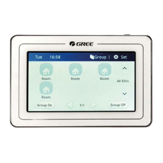
E-Smart Zone Controller 2.1 Main Page Display and Buttons Name Instructions When the controller is connected with communication System time network, current day, hour, minute, a.m./p.m.(12-hour clock); Press this button to enter group list page for group control Group entrance and editing, etc. -
Page 14: General Buttons
E-Smart Zone Controller 2.2 General Buttons Display Name Meaning Display Name Meaning Press this button Option is Return to return to the Option selected/not previous page selected Page Page One page up One page down down Press this button Press this button Edit to add group to edit the group... -
Page 15: Functions Description
E-Smart Zone Controller Fig.2.2 Page of Timer List 3 FUNCTIONS DESCRIPTION 3.1 All ON/OFF On the home page, press “Group Off” button to turn off all indoor units. Press “Group On” button to turn on all indoor units. Then indoor units will work according to memory. - Page 16 E-Smart Zone Controller (1) On/off Press the on/off button to turn unit on or off. When unit is turned off, mode, temperature, fan speed and swing can’t be set. (2) Mode setting Press the Mode buttons to set unit’s operation mode. Modes for indoor units of different series are not all the same.
- Page 17 E-Smart Zone Controller (3) Absence function can only be turned on in heating mode. When absence function is on, set temperature is 8℃. (4) Rapid cooling function can only be effective in cool mode. Likewise, rapid heating function can only be effective in heat mode. (5)...
-
Page 18: Group Control
E-Smart Zone Controller (1)、Setting of timer mode, fan speed and set temperature; The same as single unit control; (2)、Setting of timer ON/OFF time Click “Timer On **:**” zone button to enter the setting page of timer on time for setting timer on time; Press “Timer Off **:**”... -
Page 19: Local Setting
E-Smart Zone Controller Note: One set of indoor unit can be set in up to 5 groups. (2) Add group Press to add new groups. Then the page of group editing will pop in. User can set the group name and add indoor units to the group. (3)... -
Page 20: Engineering Setting
E-Smart Zone Controller Note: If user password is activated, user needs to input password to enter the control page when centralized controller is turned on or activated. (4) Backlight setting Pressing this button can set the timeout period of screen backlight. Screen will be shut off and the centralized controller will enter sleep mode when the timeout period is over. -
Page 21: Operation Notice
E-Smart Zone Controller Fig. 3.6 Setting Page of Indoor Unit Press button to select the required indoor unit that needs to be set. (1) Name: number or letter can be input(it should not be over 15 letters). (2) Icon: press to select the preset icon. (3)... - Page 22 GREE ELECTRIC APPLIANCES, INC. OF ZHUHAI Add: West Jinji Rd, Qianshan, Zhuhai, Guangdong, China, 519070 Tel: (+86-756) 8522218 Fax: (+86-756) 8669426 E-mail: gree@gree.com.cn www.gree.com...
Need help?
Do you have a question about the CE54-24/F(C) and is the answer not in the manual?
Questions and answers