Table of Contents
Advertisement
Advertisement
Table of Contents

Related Manuals for Engel F Series


Summary of Contents for Engel F Series
- Page 1 MT60F-U1 2006.9...
-
Page 2: Table Of Contents
THE TABLE OF CONTENTS 1. SPECIFICATIONS 2. UNIT BLOCK DIAGRAM 3. WIRING DIAGRAM 4. INSTALLATION 4-1 INSTALLATION AND VENTING 4-2 WIRE GAUGE IS IMPORTANT 5. TROUBLE SHOOTING 4~5 5-1 BLOCK DIAGRAM 5-2 TYPICAL TROUBLE 5-3 TECHNICAL DATA 6. CHECKING POINTS & MEASURING 6-1 Compressor input voltage 6-2 Compressor coil resistance 6-3 Thermistor resistance... -
Page 3: Specifications
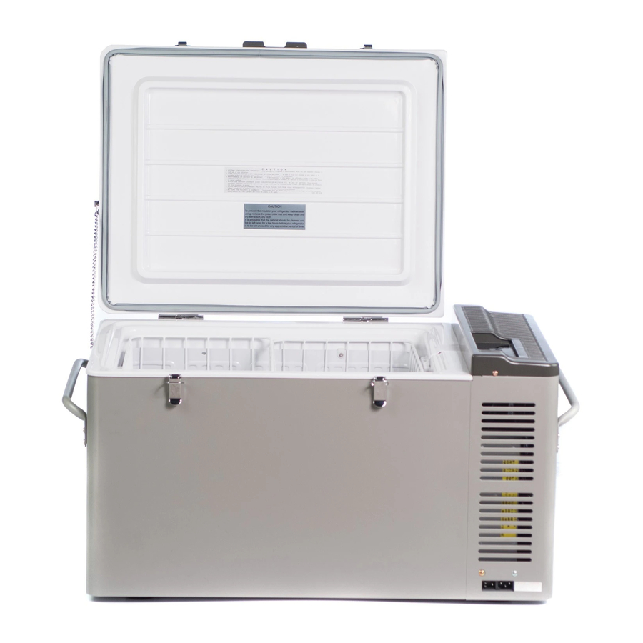
1. SPECIFICATIONS F SERIES MODEL MT60F-U1 STORAGE VOLUME ℓ(liter) 31.1×19.3×17.2 (Max. 31.6×20.5×17.4) EXTERIOR DIMENSIONS W×D×H 790×490×436 (Max. 801.5×520×441) 20.4×14.9×12.4 INTERIOR DIMENSIONS W×D×H 517×378×315 DOOR EXTERIOR FINISH Melamine coating steel plate CABINET DOOR INTERIOR FINISH A.B.S. Resin CABINET AC85〜132V 50/60Hz INPUT VOLTAGE DC 11V〜32V... - Page 4 2. BLOCK DI AGRAM OPTIONAL PARTS AC85〜132V 50/60Hz DC11〜32V 3.WIRING DAIGRAM AC85〜132V 50/60Hz DC11〜32V...
-
Page 5: Installation
4. INSTALLATION 4-1 INSTALLATION AND VENTILATION (1) Your shockproof fridge should be installed on a solid surface board or floor. (2) Be sure your fridge is not put in direct sunshine, near a gas stove, heater or other heat-generating appliances. (3) Adequate ventilation and suitable distance from each wall (at least 150mm or more) result in maximum cooling performance and minimum electric current consumption for "free standing use"... -
Page 6: Trouble Shooting
5. TROUBLE SHOOTING 5-1 BLOCK DIAGRAM Check Result Judge Repair Interval moving Input voltage DC12V, 0~10A The compressor is Replace the Compressor DC12V, 4.2A DC24V, 0~5A locked, or contaminated cooling unit works DC24V, 2.1A Lower than rated Gas is leaking or no compression amperage ( surface of condenser is ambient temperature... -
Page 8: Typical Trouble
5-2 TYPICAL TROUBLE Condition Source Measuring Result Operations Compressor coil is open circuit Compressor coil resistance is ∞Ω Replace the cooling unit No cooling ( Normal: 1.23Ω ※1 ) Power Supply brake down Power Supply output voltage is AC 0V Replace the Power Supply Control Compressor does not... -
Page 9: Checking Points & Measuring
6. CHECKING POINTS & MEASURING 6-1 Compressor input voltage (Fig. 1) ・Measure at 2 poles coupler of Power Supply or at the input terminals of the compressor. (Keep to connect the compressor when you measure it.) Readings Judgment Approx. AC14〜18V Normal AC 0 V Power Supply is broken... -
Page 10: Working Order For Replacement
7. WORKING ORDER FOR REPLACEMENT 7-1 Cooling Unit 1. Remove Motor Cover (Fig.1) Remove 4 screws which hold Motor Cover. 2. Remove 3 screws at Evaporator (Fig.2) Take out the basket first, 3. Take out Cover Pipe (Fig.3) ① Take off the cover. ②... - Page 11 2. Remove Motor Cover. (Fig.8) 3. Pull out all the couplers at Power Supply (Fig.9) ① Motor input coupler ② Fan motor coupler ③ Thermister coupler ④ Control assy coupler 4. Remove the screws at Power Supply (Fig.10) 5.Pull out Power Supply towards the top (Fig.11) 6.
Need help?
Do you have a question about the F Series and is the answer not in the manual?
Questions and answers