Table of Contents
Advertisement
Advertisement
Table of Contents

Related Manuals for Millipore Milli-Q


Summary of Contents for Millipore Milli-Q
- Page 1 ® User Manual Milli-Q Reference System...
- Page 2 Purification System. This User Manual is a guide for use during the installation, normal operation and maintenance of a Milli-Q Reference Water Purification System. It is highly recommended to completely read this manual and to fully comprehend its contents before attempting installation, normal operation or maintenance of the Water Purification System.
- Page 3 Millipore Corporation assumes no responsibility for any errors that might appear in this document. This manual is believed to be complete and accurate at the time of publication. In no event shall Millipore Corporation be liable for incidental or consequential damages in connection with or arising from the use of this manual.
- Page 4 Legal Information Continued Millipore, Elix, Q-Gard, Quantum, Milli-Q, BioPak, EDS-Pak, Millipak and Trademarks Millipore Express are registered trademarks of Millipore Corporation. The “M” Mark and RiOs are trademarks of Millipore Corporation. All other trademarks are trademarks of their respective manufacturers.
- Page 5 Milli-Q System Cabinet or inside where an electrical danger could exist. Do not remove the covers of the Milli-Q System at any time. Electrical and mechanical components inside the Milli-Q System could pose a hazard.
-
Page 6: Table Of Contents
Description of Standby Menu ...................38 Manager Menu ........................40 Description ........................40 Ready Mode ..........................43 General information ......................43 Description of Ready Menu ....................44 Using the Milli-Q System ......................47 Overview ...........................47 Dispensing water .......................48 Viewing water quality .......................51 Viewing Operation ......................52 Viewing Consumable Status .....................54 Calling Millipore .......................55... - Page 7 Alarms ............................74 Overview ...........................74 Alarm Information......................75 Summary of Alarm messages....................79 Alerts ............................81 Overview ...........................81 Alert information.......................82 Summary of Alert messages....................87 Ordering Information ........................89 Consumables, Accessories and Systems ................89 - 7 -...
-
Page 8: Product Information
Product Information Overview This chapter contains topics related to the System. Purpose Some of the more important topics in this chapter are: • installation requirements, • consumable information, and • dimensions of various components of the System This chapter contains the following topics: Contents Topic See Page... -
Page 9: Cabinet
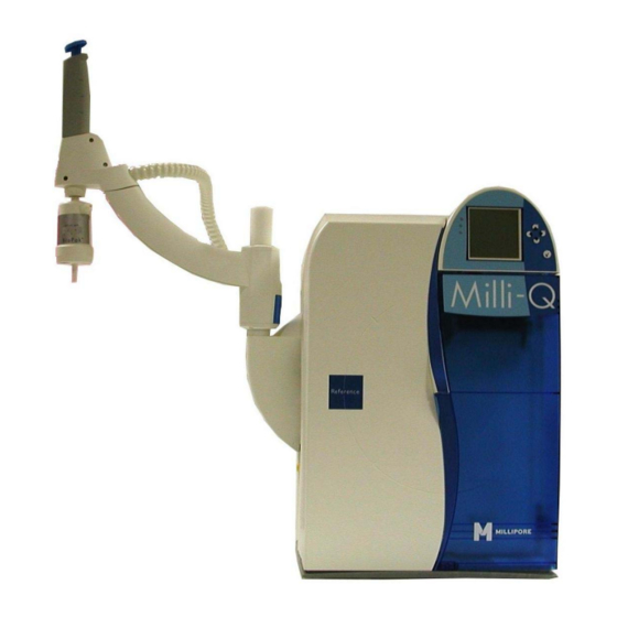
Cabinet Overview Item Description/Name Point Of Delivery (POD) POD Pak POD Arm Connections for tubings, power cord, level sensor and other cables ® Q-Gard Pack POD Mast Main Display ® Quantum Cartridge The Main Display is used to navigate the System software. Main Display function Continued on next page... - Page 10 Cabinet, Continued Details of the Main Display Item Description LEDs Main LCD Main Keypad The use of the Right Keypad button is shown below. It is used to move to the next screen. In this example, the system is changed from STANDBY Mode to READY Right Mode.
- Page 11 Cabinet, Continued The use of the Up Keypad button is shown below. It is used to scroll up in a menu. Diagram 1 Action Diagram 2 Press The use of the Down Keypad button is shown below. It is used to scroll down in a menu.
- Page 12 • a temperature of 24.9°C, and • the TOC value is: − not indicated with a Milli-Q Reference System, and − indicated with a Milli-Q Reference C+ System. NOTE: This Milli-Q Reference System does not have a built-in TOC indicator and therefore does not display a TOC value.
- Page 13 Cabinet, Continued The port and cable connections are explained below. Port and cables Item Description Item Description Feedwater port Termination Plug connection (maximum 5 VDC) Ethernet connection Accessories connection (maximum 5 VDC) (maximum 24 VDC) Level Sensor Power Entry connection (maximum 5 VDC) (100-240 VAC) - 13 -...
-
Page 14: Consumables
RO, distillation or Electrodeionisation (EDI). An example of RO or EDI feedwater is the water ® coming from either a Millipore RiOs™ System or Elix Water Purification System. This type of feedwater typically has some ions but contains little organic, particulate and colloidal contamination. - Page 15 The Quantum TEX Cartridge contains ion exchange Cartridge resin and synthetic carbon. ® These purification media are used when the Milli-Q Water needs to have both trace levels of ions and trace levels of organic molecules. The POD Pak is the final water purification device.
-
Page 16: Specifications And Requirements
100-230 VAC ±10% Frequency 50-60 Hz ±10% Main Fuse 3.15 Amp Fast Acting; 5 mm x 20 mm; 250 V safety voltage. The fuse should be serviced by a qualified Millipore Service Representative. Power Used 125 VA Power Cord Length 2.5 metres... - Page 17 Specifications and requirements, Continued Dimensions 360 mm 416 mm 458 mm 552 mm 422 mm 783 mm Please contact Millipore for a list of the Materials of Construction. Materials of construction Continued on next page - 17 -...
- Page 18 Specifications and requirements, Continued The Feedwater requirements are listed here. Feedwater Parameter Value Type Pre-treated water including one or several of the following technologies: • RO • RO + EDI • RO + DI • Distillation, and • DI. < 100 μS/cm @ 25°C Conductivity Pressure 0 bar <...
-
Page 19: Installation
Installation Overview This chapter explains how to install the System. Purpose This chapter contains the following topics: Contents Topic See Page Alarms generated during installation POD Unit, tubing and power cord Installing the Q-Gard Pack Rinsing the System Installing a POD Pak Registering UV Lamp timer Calibrating the Flowrate The steps shown below outline the sequence and major actions of a System... -
Page 20: Alarms Generated During Installation
To cancel the text display of this alarm message, follow the instructions on the LCD. This alarm occurs because the Quantum Cartridge is not fully rinsed out or MILLI-Q there is air in the tubing near a resistivity sensor. RES < SP,... -
Page 21: Pod Unit, Tubing And Power Cord
POD Unit, tubing and power cord Separate the POD Arm and the Point Of Delivery by cutting and Separate POD removing the tape that holds them together. Arm and Point Of Delivery Place the POD and POD Arm onto the POD Mast as shown below. POD Arm The Feedwater tubing is connected to either a: Feedwater... - Page 22 POD Unit, tubing and power cord, Continued • Install the Inlet Strainer as shown here. Loop • Connect one end of the feedwater tubing to the Inlet Strainer. NOTE: • A pressure regulator is normally required after the Inlet Strainer. Follow the steps below.
- Page 23 POD Unit, tubing and power cord, Continued Because the System is starting without a Q-Gard Pack or a Quantum Alarm Cartridge installed, there are alarm messages displayed. messages These alarms are: • Q-GARD PACK OUT, and • QUANTUM CARTRIDGE OUT. NOTE: The TANK EMPTY Alarm message is shown if the System is configured to have a Level Sensor.
-
Page 24: Installing The Q-Gard Pack
Installing the Q-Gard Pack Follow the steps below to install a new Q-Gard Pack. Procedure Step Action Diagram Start in STANDBY Mode. NOTE: The Q-GARD PACK OUT Alarm message is not shown at this time. By following the instructions earlier in this manual, the alarm was cancelled. - Page 25 Installing the Q-Gard Pack, Continued Procedure (continued) Step Action Diagram Push the bottom of the Q-Gard Pack inwards. Push the pack locking handle down. Close the left door. One minute later, the Main LCD shows that a new Q-Gard Pack is installed. Press - 25 -...
- Page 26 Installing the Quantum Cartridge Follow the steps below to install a new Quantum Cartridge. Procedure Step Action Diagram Open the right door of the System Cabinet. Remove the 2 protective caps located on the ports inside. Remove the covers on the 2 ports of the Quantum Cartridge.
-
Page 27: Rinsing The System
Rinsing the System Follow the steps below to rinse the System. Procedure Step Action Diagram Locate the clear tubing and the barbed fitting from the System Accessories Bag. Screw the barbed fitting onto the POD Unit. Push one end of the clear tubing onto the end of the barbed fitting. - Page 28 Rinsing the System, Continued Procedure (continued) Step Action Diagram Push the POD Plunger all the way down and then release it to stop dispensing water. Leave the System in READY Mode. - 28 -...
-
Page 29: Installing A Pod Pak
Installing a POD Pak The installation of a POD Pak involves 2 steps. These are: Overview • placing and flushing the POD Pak onto the POD Unit, and • registering the installation of a specific POD Pak. Follow the instructions delivered with the POD Pak. Placing and flushing Follow the steps below to register the installation of the POD Pak. - Page 30 Installing a POD Pak, Continued Registering (continued) Step Action Diagram Press Press In this example, you choose Millipak. Press Press Press Press 3 times on - 30 -...
-
Page 31: Registering Uv Lamp Timer
Registering UV Lamp timer The timer used for the UV 185 nm Lamp must be reset when the System is Introduction installed. If this is not done, then the message indicating that a Lamp replacement is needed is shown too early. NOTE: Before doing this, make sure that the date and time have been checked for accuracy. - Page 32 Registering UV Lamp timer, Continued Procedure (continued) Step Action Diagram Press Press Press Press 3 times on - 32 -...
-
Page 33: Calibrating The Flowrate
Calibrating the Flowrate The Milli-Q Water flowrate should be calibrated when the System is installed. Introduction A 1 Litre graduated cylinder is needed. Follow the steps below to perform a Flow Calibration. Procedure Step Action Diagram Go to STANDBY Mode. - Page 34 Calibrating the Flowrate, Continued Procedure (continued) Step Action Diagram Place a 1 L Graduated Cylinder under the POD Unit. Press Press Water dispenses automatically from the POD Unit. Wait until it stops dispensing water. Measure the amount of water (in ml) that was dispensed. Suppose 870 ml was collected.
-
Page 35: Software
Software Overview The purpose of this chapter is to explain the various software used in the Introduction System. This chapter contains the following topics: Contents Topic See Page Software Map Standby Mode Manager Menu Ready Mode - 35 -... -
Page 36: Software Map
Software Map - 36 -... -
Page 37: Standby Mode
Standby Mode General information STANDBY mode is used primarily for: Purpose • maintenance actions, and • going to the Manager Menu. Display READY Mode from Diagram 1 Action Diagram 2 STANDBY Press Mode - 37 -... -
Page 38: Description Of Standby Menu
Used to see general information about the Quantum Cartridge exchange. Install POD Pak Used to reset Alert message ‘REPLACE POD PAK’ Sanitise/clean Diagram 1 Diagram 2 Item Description System Cleaning Contact Millipore for more information. Continued on next page - 38 -... - Page 39 Description of Standby Menu, Continued Language Diagram 1 Diagram 2 Item Description Language Change the displayed language. - 39 -...
-
Page 40: Manager Menu
Manager Menu Description See the Software Map at the beginning of this chapter. The map shows how How to enter to enter the Manager Menu. To enter the Manager Menu, it is necessary to input a Login and a Password. The Software Map indicates how to input a Login and a Password. - Page 41 BioPak, EDS-Pak, POD Pak See above. Units Diagram 1 Diagram 2 Item Description • Change the displayed units of Milli-Q Product Water quality. Milli-Q Product • Choices are MΩ.cm or μS/cm. Tank • Change the displayed units of Tank Volume. Volume •...
- Page 42 Change the Temperature Compensation Mode. Flow Calibration Used for performing a flow calibration. UV 185 nm Activation Used to activate or deactivate the UV 185 nm Lamp. • Change Network settings. Network Settings • Contact Millipore for more information. - 42 -...
-
Page 43: Ready Mode
In this example, the System is powered on but is not dispensing or recirculating water. As a result, there are no water quality measurements to display. NOTE: A Milli-Q Reference System can be upgraded to have TOC measurements. Contact Millipore for more information. - 43 -... -
Page 44: Description Of Ready Menu
Description of Ready Menu Water Quality Diagram 1 Diagram 2 Item Description MQ Feed Quality View the feedwater quality (accessory) Tank Level View the level of water in the Reservoir. MQ Prod Quality View the quality of water obtained from the POD Unit. - Page 45 Item Description Application Specialist View: • name, Service Engineer • phone number, and Tech Service • email address of a Millipore Representative. Other NOTE: This information is entered by a Millipore Service Representative. Continued on next page - 45 -...
- Page 46 View information that was inputted into the System at time of servicing. Repair View information related to upcoming service. Service Contract Contract Expires NOTE: Next Service This information is entered by a Millipore Next Calibration Representative. Next Qualification Information Diagram 1 Diagram 2 Item...
-
Page 47: Using The Milli-Q System
Using the Milli-Q System Overview The purpose of this chapter is to explain: Introduction • various ways that water can be dispensed from the System, and • how to view information, operating parameters and other things about the System. This chapter contains the following topics:... -
Page 48: Dispensing Water
Dispensing water Product Water can be recirculated within the System before dispensing it. Optimise Water This helps optimised water quality. Quality Follow the steps below to do this. Step Action Diagram Start in READY Mode. NOTE: The Resistivity and temperature values may or may not be shown at this time. - Page 49 Dispensing water, Continued To dispense water, press down on the POD Unit plunger while in READY Using the Mode. POD Plunger Position Water flow Low Flow (push slightly) Medium Flow (push slightly) High Flow (push down and hold, release when done) Continuous high flow (push down and release;...
- Page 50 Dispensing water, Continued Volumetric dispensing Step Action Diagram (continued) Select the desired volume of water to be delivered. Press When the volumetric dispensing is finished, the System recirculates water for 3 minutes. The System stops recirculating water. - 50 -...
-
Page 51: Viewing Water Quality
Viewing water quality Follow the steps below to view the water quality. Procedure Step Action Diagram Make sure the System is in READY Mode. NOTE: The Resistivity (Res) and Temperature (T) are seen in the main READY Mode screen. To see Tank Level indicator, select Menu. -
Page 52: Viewing Operation
Viewing Operation VIEW OPERATION allows you to see the status of major components. Introduction Under the View Operation LCD, the following items can be selected: • System Operation, • System Alerts, • System Alarms, and • System Measures Follow the steps below to go to the System Operation LCD. System Operation Step... - Page 53 Viewing Operation, Continued System Alerts An example Alert is shown here. This is an Alert that is currently being displayed on the bottom of the Main Display in READY Mode or in STANDBY Mode. When the timer for the UV 185 nm Lamp is reset, then this Alert is no longer shown on the SYSTEM ALERTS LCD.
-
Page 54: Viewing Consumable Status
Viewing Consumable Status Consumables Status allows you to see information related to the various Introduction consumables. Follow the steps below to view Consumables Status. Procedure Step Action Diagram Start in READY Mode. Select Menu. Press Select Consumables Status. Press Select the consumable that you would like to see information about. -
Page 55: Calling Millipore
Calling Millipore Call Millipore allows you to see contact information. Introduction A Millipore Service Representative can enter this information into the System. Follow the steps below to view information under Call Millipore. Procedure Step Action Diagram Start in READY Mode. -
Page 56: Viewing Information
Viewing Information INFORMATION allows you to view: Introduction • flow schematic information, • version information, and • serial number and other information. Follow the steps below to see information about the System. Procedure Step Action Diagram Start in READY Mode. Select Menu. - Page 57 This LCD shows information such as the Serial Number and the Catalogue Number. NOTE: The Inst Date (Installation Date) needs to be entered by a Millipore Service Representative. The date is not automatically generated by the System. - 57 -...
-
Page 58: Maintenance
Maintenance Overview The purpose of this chapter is to explain the common maintenance needed for Introduction a System. This chapter contains the following topics: Contents Topic See Page Maintenance Schedule Replacing the Q-Gard Pack Replacing the Quantum Cartridge Replacing a POD Pak Cleaning the Inlet Strainer Calibrating the Flowrate - 58 -... -
Page 59: Maintenance Schedule
Prompted to by an LCD message. NOTE: It is recommended to have a Millipore Field Service Representative change the UV Lamp in the system. The replacement of this lamp involves removing the cover of the system. The instructions for replacing these lamps are not included in this User Manual. -
Page 60: Replacing The Q-Gard Pack
The Q-Gard Pack should be replaced when one of the following Alarm or When Alert messages is displayed. • Alarm message = MILLI-Q RES < SP, REPLACE Q-GARD AND QUANTUM • Alert message = REPLACE Q-GARD PACK Remove the used Q-Gard Pack by following the steps below. - Page 61 Replacing the Q-Gard Pack, Continued Removing (continued) Step Action Diagram Remove the used Q-Gard Pack. The System will indicate that the Q-Gard Pack is removed in a few moments. Follow the steps below to install a new Q-Gard Pack. Placing Step Action Diagram...
- Page 62 Replacing the Q-Gard Pack, Continued Placing (continued) Step Action Diagram Push the Pack Locking Handle down. Close the left door. The Quantum Cartridge should be replaced whenever the Q-Gard Pack is Quantum replaced in order to ensure optimal water quality. Cartridge Proceed to the next section for information about replacing the Quantum Cartridge.
-
Page 63: Replacing The Quantum Cartridge
The Quantum Cartridge should be replaced when one of the following Alert When or Alarm messages is displayed. • Alert message = REPLACE QUANTUM CARTRIDGE • Alarm message = MILLI-Q RES < SP, REPLACE Q-GARD AND QUANTUM The Quantum Cartridge should be replaced whenever the Q-Gard Pack is replaced. - Page 64 Replacing the Quantum Cartridge, Continued Follow the steps below to install a new Quantum Cartridge. Placing Step Action Diagram Remove the covers on the 2 ports of the Quantum Cartridge. Wet the O-rings with water. Install the Quantum Cartridge until it is fully seated. Close the right door.
- Page 65 Replacing the Quantum Cartridge, Continued The Quantum Cartridge, when newly installed, needs to be rinsed. This Rinsing ensures optimal water quality. Step Action Diagram Locate the clear tubing and the barbed fitting from the System accessories bag. Screw the barbed fitting onto the POD Unit.
- Page 66 Replacing the Quantum Cartridge, Continued Rinsing (continued) Step Action Diagram Dispense water for about 10 minutes. This flushes out any trapped air in most of the System. This also rinses off the purification media located in the Q-Gard Pack and the Quantum Cartridge.
-
Page 67: Replacing A Pod Pak
Replacing a POD Pak One possible reason for a decrease in Milli-Q Water flowrate is a clogged Basing on POD Pak. The POD Pak should be replaced when it appears to be clogged. flowrate Make sure the POD Pak is not air-locked. Dispense water and open the vent to see if there is any trapped air. - Page 68 Replacing a POD Pak, Continued Registering (continued) Step Action Diagram Scroll down to Install POD Pak. Press Press In this example, the replacement POD Pak is a Millipak. Press Press Continued on next page - 68 -...
- Page 69 Replacing a POD Pak, Continued Registering (continued) Step Action Diagram Press Press 3 times on - 69 -...
-
Page 70: Cleaning The Inlet Strainer
Cleaning the Inlet Strainer The purpose of the Inlet Strainer is to prevent a large particle from entering Purpose the System. If the Inlet Strainer becomes clogged, then feedwater does not flow freely to the System. Cleaning the Inlet Strainer removes any trapped debris. The Inlet Strainer should be cleaned when the following Alert message is When displayed. - Page 71 Cleaning the Inlet Strainer, Continued Registering (continued) Step Action Diagram Select Menu. Press Select Maintenance. Press Select Clean Strainer. Press A picture is shown. Press Press Continued on next page - 71 -...
- Page 72 Cleaning the Inlet Strainer, Continued Registering (continued) Step Action Diagram Press 3 times on Go to READY Mode. - 72 -...
-
Page 73: Calibrating The Flowrate
Calibrating the Flowrate The flowrate should be calibrated when a: When • new consumble is installed such as a: − POD Pak, or − Q-Gard Pack, and − Quantum Cartridge • sensor or major component is changed. • feedwater parameter has changed such as the: −... -
Page 74: Alarms
Alarms Overview The purpose of this chapter is to explain the Alarm messages shown on a Introduction System. Specifically, this chapter explains how: • an Alarm message is displayed, • to read an Alarm message, • to cancel an Alarm, and •... -
Page 75: Alarm Information
Definition required for the System. It is not recommended to use the System when an Alarm message is shown. Contact Millipore if an Alarm message is shown and the problem can not be Alarm shown – resolved. what to do? The following table summarizes the different types of Alarm messages. - Page 76 Alarm Information, Continued When an Alarm is shown, it is listed under the System Alarms LCD. System Alarms See the section <View Operation> for information on how to access this LCD. Follow the steps below to view an Alarm message. Viewing an Alarm Message Step...
- Page 77 • fixing the cause of the Alarm, or Alarm message • using the Keypad. This cancels the display of the Alarm message for 1 hour. In this example, the Alarm message is MILLI-Q T > MAX. Alarm – before cancelling Main Display...
- Page 78 Alarm Information, Continued Alarm – after Main Display LEDs Main Display cancelling the text display ê Now suppose a Millipore Service Representative fixes the cause of the Alarm. Alarm – fixed Main Display LEDs Main Display ê - 78 -...
-
Page 79: Summary Of Alarm Messages
MILLI-Q INTER T > MAX The Intermediate temperature is out of measurement range. Contact Millipore. MILLI-Q RES < SP, REPLACE The Milli-Q Water resistivity is < Q-GARD AND QUANTUM set point. Dispense water to eliminate any trapped air in the System. - Page 80 Continued Alarm messages LCD message What it means (continued) MILLI-Q RES > MAX The Milli-Q Water resistivity is out of measurement range. Contact Millipore. MILLI-Q T < MIN The Milli-Q Water temperature is out of measurement range. Contact Millipore. MILLI-Q T > MAX The Milli-Q Water temperature is out of measurement range.
-
Page 81: Alerts
Alerts Overview The purpose of this chapter is to explain the Alert messages shown on a Introduction System. Specifically, this chapter explains how: • an Alert message is displayed, • to read an Alert message, • to cancel an Alert, and •... -
Page 82: Alert Information
Alert information An Alert message corresponds to a maintenance request. Most of the Alert Purpose messages are related to the replacement of a consumable. The following table summarises the different types of Alert messages. Types Type Description Minor Alert A minor alert message indicates that a maintenance action is needed within a number of days. - Page 83 Alert information, Continued Follow the steps below to view an Alert message. Viewing an Alert Message Step Action Diagram Start in either READY or STANDBY Mode. Press Press Press Press Continued on next page - 83 -...
- Page 84 Alert information, Continued A Minor alert message can be cancelled by: Cancelling a • performing the maintenance action (i.e. replace consumable), Minor Alert message - • using the Keypad (see below), or procedure • a Major Alert message is shown. This eliminates the Minor Alert message.
- Page 85 Alert information, Continued The Alert message has been cancelled but the cause of the message is still Minor Alert - active. after cancelling Main Display LEDs Main Display ê The Alert message has been cancelled when the A10 Lamp has been replaced. Minor Alert - consumable replaced...
- Page 86 Alert information, Continued The Alert message has been cancelled but the cause of the message is still Major Alert – active. after cancelling Main Display LEDs Main Display ê The Alert message has been cancelled when the POD Pak has been replaced. Major Alert - consumable replaced...
-
Page 87: Summary Of Alert Messages
Q-Gard Pack is < Set Point. ORDER Q-GARD AND The Q-Gard Pack and Quantum QUANTUM Cartridge are replaced together. Contact Millipore about ordering a replacement Q-Gard Pack and Quantum Cartridge. NEXT CALIBRATION VISIT The System is prompting you that a IN XX DAYS Calibration Visit should be scheduled. - Page 88 Replace the Quantum Cartridge. REPLACE UV 185 NM LAMP The System has determined that the UV 185 nm Lamp should be replaced. Contact Millipore. REPLACE UV 185 NM LAMP The System has determined that the IN XX DAYS UV 185 nm Lamp should be replaced in XX days, where XX is 15, …, 1.
-
Page 89: Ordering Information
Ordering Information Consumables, Accessories and Systems Consumables Item Catalogue Number BioPak Ultrafilter CDUFBI001 ® MPGP04001 Millipak Express 40 Final Filter ® EDSPAK001 EDS-Pak Final Filter EDS-Pak Installation Kit EDSKIT001 - ordered 1 time only for multiple EDS-Pak uses. Q-Gard T1 Pack QGARDT1X1 Q-Gard T2 Pack QGARDT2X1... - Page 90 Regularly scheduled preventive maintenance/calibration will help you obtain Note the best performance from your Millipore water purification system throughout its entire lifetime. Please contact your Millipore representative to find the best options for your system including our maintenance programs. - 90 -...
Need help?
Do you have a question about the Milli-Q and is the answer not in the manual?
Questions and answers