
Summary of Contents for Ovation Grid-Lok
- Page 1 Grid-Lok Installation Manual Panasonic CM602/402 placement machines www.Ovation-Products.com...
-
Page 3: Table Of Contents
Contacts............22 Issue 1 Grid-Lok Installation Manual... -
Page 4: Manual Scope
No liability can be accepted by the publishers for any machine issues or failures, subsequent to a Grid-Lok installation using this guide. In all cases Ovation Products recommend the use of a properly trained engineer to complete the works. The Installation Manual is intended to be used in conjunction with the Grid-Lok Technical Manual, which is included with the kit. -
Page 5: Tools Required
Controller, Machine tables, Pneumatic connection cables, Standard Grid-Lok™ modules and Power Supply cable (to fit to the Panasonic components Aux Power Supply Unit). Controller manifold/... - Page 6 CHAPTER 2 Kit description Tooling modules (number dependant on exact kit) Regulator kit and mounting bracket Power supply cable Grid-Lok Installation Manual Issue 1...
- Page 7 Y fitting (one per machine) Machine connection 10mm tube T fitting to 8mm reducer (one per machine) Table up air pressure sense 6mm to 4mm reducer (4 per machine) Control box to table (4 per machine) Issue 1 Grid-Lok Installation Manual...
-
Page 8: Preparation
2. There is a requirement to remove some machine panels ad feeder banks/carts during the install of Grid-Lok to allow access to the machine and Pneumatics enclosure for routing of tubes and cables. -
Page 9: Locating The Kit
411_CTL controller as follows: location 1. The Grid-Lok 411_CTL controller fits in the front middle compartment of the CM602 machine. It is recommended to remove the front feeder carts when fitting the Grid-Lok 411_CTL and tubing connections Issue 1 Grid-Lok Installation Manual... -
Page 10: Air Solenoid Location
Air solenoid Locate the air solenoid compartment on the LH side of the machine location Remove door, dial manifold and Digi one unit to gain easier access to CMs air valves for tables A1 and A2. Grid-Lok Installation Manual Issue 1... - Page 11 Locate the air solenoid compartment on the RH side at the rear of location the machine. Remove door, dial manifold and Digi one unit to gain easier access to CMs air valves for tables B1 and B2. Issue 1 Grid-Lok Installation Manual...
-
Page 12: Aux Power Supply Location
CHAPTER 4 Locating the kit Aux power Locate the Aux Power Supply on the RH side of the machine supply location Grid-Lok Installation Manual Issue 1... -
Page 13: Connecting Up
CHAPTER 5 Connecting up Overview The following drawing shows an overview of the Grid-Lok ™ 411_CTL system connections. The actual Grid-Lok™ modules are not shown for clarity, see the diagram on page 12 for more details. Operator Sensor Inputs Plug-In... -
Page 14: Locating And Fitting Power And Air Connections
Machine regulator controller and replace with tube provided, connecting the Machine regulator to the Grid-Lok regulator. If the air tube used is 10mm then used the adapter supplied Connect the power supply cable to the Aux Power Supply box, and route to the 411_CTL control box located in the front middle compartment. - Page 15 8 to the 6mm open connection, connect control box provided 4mm airline to 4mm adapter. Connect the other end of 4mm line to the Control Box located in the front middle compartment. Repeat this for all 4 tables Issue 1 Grid-Lok Installation Manual...
- Page 16 Table up to Connect the 4mm tubes from the table up air valves to the control pressure box as shown below sensor on control box Pressure sensor Connections Table A1 Table A2 Table B1 Table B2 Grid-Lok Installation Manual Issue 1...
-
Page 17: Manifold To Modules
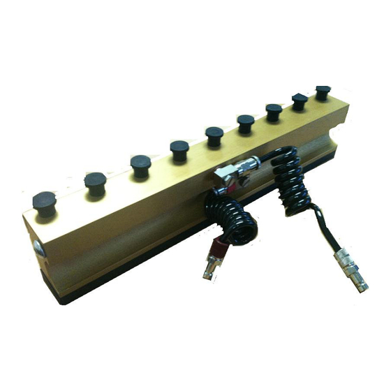
Manifold to 1. Remove the OEM CM602 table from the machine and replace with modules table assembly supplied in the Grid-Lok 2. Ensure that the Distribution bar Air connections are at the back when sliding the table into the machine 3. -
Page 18: Pin Up And Pin Lock Air Connections To Table
Connect the tube with the grey strip to the Red distribution to tables bar and the plain black tube to the silver distribution bar. Table LH side (Red Distribution Bar) Pin lock air connection to tables Table RH side (Silver Distribution Bar) Grid-Lok Installation Manual Issue 1... -
Page 19: Specific Details And Instructions
• Set/Reset - To raise and lower the tooling pins (in semi- automatic mode) • Auto/Manual - Automatic or Semi-Automatic mode NOTE The Set/Reset switches are disabled if automatic mode is selected Auto/Manual Table A1 Set/Reset Table A2 Set/Reset Table B1 Set/Reset Table B2 Set/Reset Issue 1 Grid-Lok Installation Manual... -
Page 20: Adjustments And Settings
NOTE Adjustment of the air control regulator may be required when changing the amount of tooling modules used. I It is important to adjust the flow control valve so that all the pins rise smoothly Grid-Lok Installation Manual Issue 1... -
Page 21: Adjusting Module Timing
4. Each increment is 50ms of time. 0 = No Delay. 5. Once the required delay is set, gently replace the 411_CTL cover ensuring all control boards are correctly inserted and no wires are pinched between the cover and main control box cover Issue 1 Grid-Lok Installation Manual... -
Page 22: Technical Reference
CHAPTER 8 Technical reference NOTE Preventive Maintenance Tasks are the only authorized maintenance tasks that may be carried out on the Grid-Lok tooling system. Grid-Lok Installation Manual Issue 1... - Page 23 CHAPTER 8 Technical reference Issue 1 Grid-Lok Installation Manual...
-
Page 24: Contacts
CHAPTER 9 Contacts Grid-Lok Installation Manual Issue 1... - Page 26 Grid-Lok Installation Manual www.Ovation-Products.com...
Need help?
Do you have a question about the Grid-Lok and is the answer not in the manual?
Questions and answers