Table of Contents
Advertisement
Quick Links
Advertisement
Table of Contents

Related Manuals for HTC Outfeed Rollers HOR-1038U

Summary of Contents for HTC Outfeed Rollers HOR-1038U
- Page 1 Operators Manual FOR MODELS: HOR-1038U Covered by U.S. Patent No. 4,640,326...
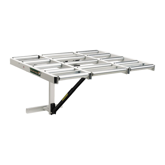
- Page 2 Thank You and Congratulations! Thank you for your recent purchase of HTC Outfeed Rollers. This product is manufactured by craftsmen dedicated to making high quality, reliable products. All HTC products are backed by our Limited Lifetime Warranty* and a responsive, dedicated customer service department. We would appreciate hearing your comments or suggestions. Please feel free to call or write anytime. We welcome correspondence from everyone who has ever purchased or used one of our fine products. A Word About Your New Outfeed Rollers A unique patented HTC exclusive! A work support that’s always in place and ready to use. Outfeed Rollers support the workpiece to 4' past the blade. That’s a full 48" to help balance a full 8' panel. HTC Outfeed Rollers are compatible with most fence systems on the market and have a patented cam action adjustment that lowers the Outfeed Rollers 3/8" for proper support of sliding cross-cut and miter slot fixtures. Folds down easily for compact storage and swings into place without the use of tools. When you work with full 4' x 8' panels and extra long boards, HTC Outfeed Rollers let you rip and cross-cut easily, accurately... but most importantly safer by yourself. General Product Safety Warning As with all products there are certain hazards involved with their operation and use. Using any product with respect, caution, and common sense will considerably lessen the possibility of personal injury. Safety is a combination of staying alert, knowing how the product works, and knowing how to properly use the product. To use any product safely you should plan ahead and practice the proper steps prior to actually using the product. If safety rules and instructions are overlooked or ignored, personal injury to the operator or other people in the area may result. Safe operation of any product requires that you read and understand the product instructions and all labels affixed to the product.
-
Page 3: General Safety Rules
General Safety Rules The following general safety rules are supplied as an aid for the safe use of many products. This is NOT a complete list of all possible safety rules. Safe use of a product includes but should NOT b e limited to the following safety rules. For your own safety, read instruction manual 15. Keep guards in place. Be sure that guards, hold- before operating the tool. Know the tool. Read and downs, and antikickback devices are in working order, understand the owner’s manual and labels affixed to the and positioned properly, and are in proper adjustment tool. and alignment. Keep work area clean. Cluttered areas and benches 16. Remove adjusting keys and wrenches. Form the invite accidents and create fire hazards. - Page 4 Attention Delta Unisaw Owners If your table saw is a Delta Unisaw, with an LVC (Low Voltage Controller) 3" box mounted on the rear of the table saw cabinet, please read and follow the instructions in this section carefully before proceeding with installation of the HTC Outfeed Roller System. Otherwise skip to next page. The LVC box may need to be lowered 3" to provide enough space for the top mounting channel of the Outfeed Roller Main Frame. Read through the entire installation instructions prior to moving your LVC box. The following instructions will guide you step by step through the simple procedure of lowering the LVC box, if necessary. Tools needed to lower the Delta Unisaw LVC Box LVC box may need to be lowered 3" Safety goggles Hand drill with 1/8" and 11/32" drill bits Scribe, awl or marking device File or deburring tool to remove sharp edge from holes Center punch Ball peen hammer 1-1/2" diameter hole saw (available at any hardware store) Two (2) 1/2" wrenches Lowering the Delta Unisaw LVC Box WARNING: To avoid electrocution disconnect power from the table saw before proceeding.
- Page 5 Page left intentionally blank.
-
Page 6: Unpacking And Checking Contents
Unpacking and Checking Contents Separate all parts and hardware from packing materials. Check each part with the table and hardware chart to make sure all items are accounted for and are in good condition. Do not discard packaging materials until assembly is completed and you are satisfied with the product. Part # Name 5131 Upper Support Bracket 2887 Stud Pad G501 Tube Closer Plug C206 5/16"-18 X 1" Hex Bolt 5132 Lower Support Bracket C408 3/8"-16 Acorn Nut 2272 3/8" Pivot Rod C204 5/16"... - Page 7 WARNING: Do not attempt to use the product if parts are missing. Contact factory at 800-624-2027 to obtain the necessary parts. Main Frame Roller Frame SET BASELINE AT 3 " BELOW TOP FINISHED SURFACE OF TAPE THIS TEMPLATE TO MACHINE CABINET MACHINE TABLE WITH “BASE LINE” EXACTLY 3 " BELOW FINISHED SURFACE OF MACHINE TABLE AND “CENTER LINE”...
-
Page 8: Installation Instructions
Installation Instructions Tools needed for Assembly Safety goggles Scribe, awl or marking device for marking on sheet metal Center punch Ball peen hammer File or deburring tool to remove sharp edge from holes Combination square Framing square or long straight edge Hand drill with 1/8" and 11/32" drill bits 1/2" deep socket wrench 1/2" open end wrench Figure 1 7/16" socket wrench and/or open end wrench Note: Read through ALL installation instructions and review all diagrams before attempting installation. WARNING: To avoid electrocution disconnect power from the table saw before proceeding. - Page 9 READ THROUGH ENTIRE INSTALLATION INSTRUCTIONS BEFORE PROCEEDING 1. Position and mount with tape the enclosed Main Frame Mounting Template to the rear of Table Saw, as shown in Figure 1. Set the Base Line (on the template) 3 1/2" below the table top surface of the table saw. Figure 2 Important: Base Line must be parallel with the table top or Outfeed Roller unit will not work properly. 2. Using a center punch, mark the four (4) mounting holes on the Template. Drill 1/8" pilot holes to reduce bit wander in sheet metal. Then enlarge holes by drilling with 11/32" drill to accommodate 5/16" mounting bolts. Step drills work especially good in sheet metal. 3. Mount the Main Frame A to the saw cabinet using two (2) stud pads B, along with (2) 5/16"-18 x 1" bolts D, (2) 5/16" - 18 nuts J, (4) 5/16" flat washers H and (4) 5/16" lock washers I. (Hand tighten only.) Tip: When installing the stud pads and Main Frame on some machine Figure 3 models, you’ll need to “hang” the stud through one of the holes, then rotate the stud pad into position and thread the bolt into place. Usually Pivot the back of the saw cabinet can be reached from the opening on the side Pivot of the saw. On the rare occasions it’s necessary to lay the saw on its side and feed them in from the bottom. Figure 2. Roller Bolt Bolt Roller Frame 4. Assemble the Lower Main Frame Bracket to the Main Frame. Mount as Lock Knob low as is practically possible, for best results. It can be flipped over if...
- Page 10 9. Pivot the Roller Frame back over and attach the upper end of the Support Arm to the Adjustment Plate L using a Pivot Rod G and (2) two Acorn Nuts F. 10. Insert (2) 9 1/2" Rollers into Roller Frame as shown in Figure 7 & 8. Use thin putty knife (or something similar) to compress the spring loaded axle. Note: It is very important to install the rollers with fixed end in outside frame. You are now ready to make the final adjustments to your Outfeed Roller. 11. Lay a straight edge on saw table top extending out to first roller closest to saw table (Figure 9). Adjust position of Main Frame to bring both ends of rollers level with saw table top. Table remains folded down — cams positioned as in Figure 3 & 4. Tighten top Main Frame nuts and bolts. Figure 7 12. Swing roller section into it’s extended position. Tighten or loosen Adjustment Bolt to bring outboard rollers level and parallel with saw table This End Must Be Inserted First top. Tighten the top leveling bracket mounting bolts Figures 10 & 11. 13. Double check and make sure Roller Section is mounted level with the " 13" saw table top (side to side). Then mark and drill lower mounting holes. Install (2) 5/16" - 18 x 1" bolts with flat washers through the outside of the saw cabinet, with flat washers H, lock washers I, and 5/16" - 18 Pivot Pin nuts J on the inside. Tighten securely. Note: Before drilling the lower mounting holes on some saw models you Figure 8 may find the angled dust pan within the cabinet becomes an obstruction to proper installation. You may want to adjust the position of Lower Main Frame Bracket.
-
Page 11: Care And Maintenance
Outfeed Roller Feature Rip Cuts and Operating Instructions Workpiece Cam Action Up Position The unique cam-action of the HTC Outfeed Rollers allow the roller surface to be quickly and easily lowered 3/8" to support the miter gauge bar. This Figure 12 allows the use of miter or cross-cut boxes or any other sliding miter fixtures or jigs. The cam-action assures that the rollers remain parallel to the table saw and that the fully adjustable height mechanism remains in precise alignment with the table saw surface and miter gauge slot. Cross Cuts Figure 12 shows the cam-action in the down position with the rollers in the Guide Bar up position for supporting the workpiece in a normal cutting mode. Workpiece Figure 13 shows the cam-action in the up position with the rollers in the down position to support the miter gauge guide bar for jig or fixture mode. Down Position Storage Figure 13 How to Fold Outfeed Rollers... -
Page 12: Limited Lifetime Warranty
LIMITED LIFETIME WARRANTY Products manufactured by HTC Products are guaranteed to be free from defects in material and workmanship under normal use and service. HTC’s obligation under this warranty shall be limited to repairing or replacing for the original owner, at our option, any part of said equipment which HTC’s examination shall disclose to its satisfaction to be defective. Any said product or component claimed to be defective is to be sent prepaid to: HTC Products, 1161 Rankin Dr., Troy, MI 48083 Attn: Warranty Department, together with a copy of the original, dated sales receipt. Call for authorization number before shipping. This warranty does not apply to damages resulting from shipping, accident, misuse, abuse or alteration.
Need help?
Do you have a question about the Outfeed Rollers HOR-1038U and is the answer not in the manual?
Questions and answers