Advertisement
Quick Links
Installation Instructions
Model CC-5
System Cardcage for NCCNT WAN
INTRODUCTION
OPERATION
PRE-INSTALLATION
P/N 315-099319-4
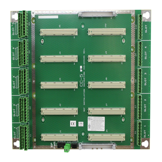
The Model CC-5 Cardcage from Siemens Industry, Inc. (see Figure 1) has five card
slots and occupies two positions on the studs in the backbox or on the optional
CAB-MP Mounting Plate. The CC-5 is used for mounting all system circuit card
assemblies. It has two removable terminal block connectors at the top and one
removable terminal block connector at the bottom of each card slot. All field-wiring
connections are made directly to the top of the cardcage while internal power is
connected to the bottom of the cardcage. The two removable terminal block connec-
tors at the top of each slot are arranged in two rows. The lower row is labeled 1
through 8 and the upper row is labeled 9 through 16. These removable terminal
block connectors are used for connecting power limited external equipment. The
removable terminal block connector located at the bottom of each slot is labeled 17
through 24 and is used for connecting internal power.
Figure 1
CC-5 Card Cage
The CC-5 provides a central point for mounting circuit card assemblies. If a card
requires power, it is applied through the removable terminal block at the bottom of
the cardcage. All external devices for the card are connected to the card through the
two removable terminal blocks at the top of the cardcage. The circuit card assemblies
are connected to the HNET bus through the connectors on the cardcage.
The CC-5 is shipped with the card guides removed. The card guides are keyed to
assist in installation. They can be installed either before or after the cardcage is
installed in the enclosure. For ease of installation, the card guides have been de-
signed to be installed after the field wiring has been completed.
Note:
Board shown without
card guides installed.
Siemens Industry, Inc.
Building Technologies Division
Advertisement

Related Manuals for Siemens CC-5


Summary of Contents for Siemens CC-5
-
Page 1: Installation Instructions
HNET bus through the connectors on the cardcage. PRE-INSTALLATION The CC-5 is shipped with the card guides removed. The card guides are keyed to assist in installation. They can be installed either before or after the cardcage is installed in the enclosure. -
Page 2: Installation
Remove all system power before installation, first battery then AC. (To power up, connect the AC first, then the battery.) The CC-5 mounts at the back of the enclosure on the studs in the backbox or on the optional Mounting Plate (CAB-MP). The Mounting Plate may be located either “IN” or “OUT”... - Page 3 Each row of studs in the backbox or each Mounting Plate can hold a maximum of two CC-5 cardcages. There are three possible locations for mounting the CC-5. Flush left in the backbox or on the Mounting Plate in positions 1-2.
- Page 4 Mounting The CC-5 On The Optional CAB-MP WIRING At the top and bottom of the CC-5 and adjacent to each card slot are removable terminal blocks. The wiring to the two terminal block connectors at the top of the CC- 5 is power limited.
-
Page 5: Specifications
10.58”W x 14.25”H Electrical Ratings: The PSC-12 supplies the power to the two 60-pin Data bus connectors (P1 and P2) in the CC-5. The total rating for all CC-5s in any given enclosure is as follows: 24 VDC, 2 Amps max 6.2 VDC,... - Page 6 This page was left intentionally blank. Siemens Industry, Inc. P/N 315-099319-4 Building Technologies Division...
- Page 7 This page was left intentionally blank. Siemens Industry, Inc. P/N 315-099319-4 Building Technologies Division...
- Page 8 Siemens Industry, Inc. Siemens Building Technologies, Ltd. Building Technologies Division Fire Safety & Security Products Florham Park, NJ 2 Kenview Boulevard P/N 315-099319-4 Brampton, Ontario L6T 5E4 Canada...