Advertisement
Quick Links
Si4010 D
1. Key Fob Development Platform
The Si4010 key fob development platform is a flexible platform for comfortably developing software and testing the
whole system using the Silicon Laboratories software development IDE. The platform also allows programming of
the NVM on chip. The kit has three versions: one for the 434 MHz band (P/N 4010-KFOBDEV-434), one for the
868 MHz band (P/N 4010- KFOBDEV-868) and one for the 915 MHz band (P/N 4010-KFOBDEV-915).
1.1. Kit Content
Qty
2
1
3
1
1
1
1
1
1
1
1
1
2
2
2
1
3
1
1
Rev. 0.1 6/12
Downloaded from
Elcodis.com
electronic components distributor
EVELOPMENT
Part Number
4010-KFOBDEV-434
4010-KFOB-434-NF
Si4010 key fob demo board 434 MHz w/o IC
MSC-DKPE1
SOIC/MSOP socketed development board
Si4010-C2-GS
Si4010-C2-GS transmitter IC, SOIC Package
4010-DKPB434-BM
Si4010 MSOP key fob development board 434 MHz, SMA
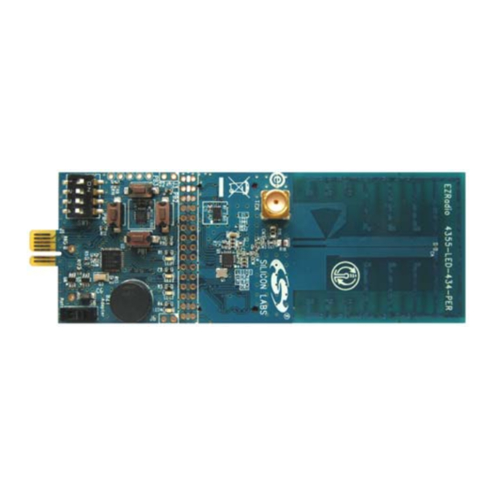
4355-LED-434-SRX
Si4355 RFStick 434 MHz receiver board
MSC-PLPB_1
Key Fob Plastic Case (translucent grey)
MSC-BA5
Programming interface board
MSC-BA4
Burning adapter board
EC3
USB Debug Adapter
Toolstick_BA
Toolstick Base Adapter
MSC-DKCS5
USB Cable
USB extender cable (USBA-USBA)
AAA
AAA battery
CRD2032
CR2032 3 V coin battery
4010-KFOBDEV-868
4010-KFOB-868-NF
Si4010 key fob demo board 868 MHz w/o IC
MSC-DKPE1
SOIC/MSOP socketed development board
Si4010-C2-GS
Si4010-C2-GS transmitter IC, SOIC Package
4010-DKPB868-BM
Si4010 MSOP key fob development board 868 MHz, SMA
4355-LED-868-SRX
Si4355 RFStick 868 MHz receiver board
Copyright © 2012 by Silicon Laboratories
K
U
'
I T
SER
S
Table 1. Kit Content
Description
Si4010 Key Fob Development Kit 434 MHz
Si4010 Key Fob Development Kit 868 MHz
S i 4 0 1 0 - D K
G
UIDE
Si4010-DK
Advertisement

Related Manuals for Silicon Laboratories 4010-KFOBDEV-434


Summary of Contents for Silicon Laboratories 4010-KFOBDEV-434
- Page 1 Silicon Laboratories software development IDE. The platform also allows programming of the NVM on chip. The kit has three versions: one for the 434 MHz band (P/N 4010-KFOBDEV-434), one for the 868 MHz band (P/N 4010- KFOBDEV-868) and one for the 915 MHz band (P/N 4010-KFOBDEV-915).
- Page 2 Si4010-DK Table 1. Kit Content (Continued) MSC-PLPB_1 Key Fob Plastic Case (translucent grey) MSC-BA5 Programming interface board MSC-BA4 Burning adapter board USB Debug Adapter Toolstick_BA Toolstick Base Adapter MSC-DKCS5 USB Cable USB extender cable (USBA-USBA) AAA battery CRD2032 CR2032 3 V coin battery 4010-KFOBDEV-915 Si4010 Key Fob Development Kit 915 MHz 4010-KFOB-915-NF...
- Page 3 Si4010-DK 1.1.1. Burning Adapter (P/N MSC-BA4) The programming interface board serves as an interface in between the debug adapter and the Socketed Key Fob Development Board or the Development Key Fob. It provides 6.5 V for NVM programming. The power source is activated by a sliding switch on the board.
- Page 4 Si4010-DK 1.1.3. Si4010 MSOP Key Fob Development Board 434 MHz, SMA (P/N 4010-DKPB434-BM) This development board has an unburned soldered Si4010, five push buttons, matched 50 SMA RF output, battery clip, and battery switch. This board allows running user application from RAM during program development even while board is disconnected and powered by the battery.
- Page 5 Si4010-DK 1.1.6. 4010 Key Fob Demo Board 434 MHz without IC (P/N 4010-KFOB-434-NF) 1.1.7. Key Fob Plastic Case (translucent grey) (P/N MSC-PLPB_1) 1.1.8. Toolstick Base Adapter (P/N Toolstick_BA) Debugging adapter compatible with Si4355 RFstick receiver board and the Si4010 development boards. 1.1.9.
- Page 6 Si4010-DK 1.1.11. EC3 Debug Adapter (P/N EC3) Silicon Labs debugging adapter, used by other Silicon Labs’ MCU products as well, compatible with the development platform. Rev. 0.1 Downloaded from Elcodis.com electronic components distributor...
- Page 7 Si4010-DK 1.2. Other Boards The following boards are not part of the development kit but can be ordered separately from Silicon Labs. Part Number Description 4010-DKPB434-BS Si4010 SOIC key fob development board 434 MHz, SMA 4010-DKPB_434 Si4010 key fob development board 434 MHz 4010-DKMX_434 Si4010 matrix keyboard development board 434 MHz 4010-KFOB-315-NF...
- Page 8 Si4010-DK 1.3. Usage of the Key Fob Development Platform The Silicon Labs IDE communicates with the USB Debug Adapter through the USB bus. The following debugging scenarios are possible: 1. EC3 debug adapter Burning adapterSi4010 socketed key fob development board This setup is suitable for downloading, running, and debugging the program in RAM or burning the program in the NVM and running it.
- Page 9 4 kB version with no code placement limitation by following the directions given in application note AN104 about Keil toolchain integration and license management. Unlock code can be found on the WDS CDROM in the root folder in the Keil_license_number.txt file. Contact your Silicon Laboratories sales representative or distributor for application assistance.
- Page 10 Si4010-DK 2.3. IDE Features The IDE allows the following: 1. Download the OMF-51 linker output format (Keil BL51 linker output, for example) and match the source code lines with the compiled file. This allows source code debugging, including variable value viewing, set- ting breakpoints, single-stepping, etc.
- Page 11 Si4010-DK 2.6. Device Version 1. The device ID information can be read through the IDE through Views Debug Windows Si4010 XREG Regs. The last item bREV_ID is the device revision. The user can also call the API function bSys_GetRevId().
- Page 12 Si4010-DK Facts about using the LED with IDE chain: 1. The IDE chain can connect to the device only if the LED current driver is off and the LED is not lit. 2. Once the IDE chain is connected to the device it blocks the device LED driver. Therefore, the application can be written in a normal fashion using LED as desired in the final application without worry of being dis- connected from the debug chain.
- Page 13 Si4010-DK The intensity setting can be changed any time, even when the GPIO_LED = 1. This is basically how the LED control operates. This approach will work when the part status is finalized as the Run device, since for that program level the C2 interface is turned off after the boot-by-boot routine. However, when the code above is used for a device in the Factory or User programming state, then the GPIO4 will stop working after the first LED blink.
- Page 14 Si4010-DK If we disable the C2 interface when the device is not connected to the IDE chain, and before the LED is turned off when lit, then there will not be the GPIO4 problem. To do that the user must add the following function to the user application to turn the LED on.
- Page 15 Si4010-DK *------------------------------------------------------------------------------ Assembly version of the same function, assuming that the file name is ledon.a51 for Keil toolchain. ;------------------------------------------------------------------------------ INCLUDES: $NOLIST $INCLUDE (si4010.inc) $LIST ;--------------------------------------------------------------------------- SEGMENTS: ; Assumes file name to be ledon.a51 .. capitalized LEDON is the file name NAME LEDON ?PR?vLedOn?LEDON SEGMENT CODE...
- Page 16 Si4010-DK ; -- End of assembly ;--------------------------------------------------------------------------- The function is able to determine whether the device is connected to the IDE chain. If it is not connected, then the function turns the C2 interface off. Once that is done it is not possible to turn the C2 interface back on unless the power to the device, or at least to the digital portion of the device, is cycled.
- Page 17 Si4010-DK 3. The vLedOn() function code is bigger than simple GPIO_LED=1 and is not necessary for the Run part, so conditional compilation for LED bug may still be an option. One recommendation for using the vLedOn() function is that the user application would include monitoring of several buttons pressed simultaneously.
- Page 18 Si4010-DK 3. Examples provided There are 5 demonstration examples provided with the development kit documentation pack: 1. aes_demo 2. fcast_demo 3. fstep_demo 4. tone_demo 5. keyfob_demo 6. rke_demo All are precompiled and ready to be used without compilation for convenience. The user just needs to go to the <name>_demo/bin directory and open the Silicon Labs IDE *.wsp project file by the Silicon Labs IDE.
- Page 19 Si4010-DK 3.5. Simple key fob demo-keyfob_demo This example demonstrates a basic key fob application transmitting a packet for every button push. Packets can be received by an 4355-LED-XXX-SRX board. Buttons are debounced using the Button Service API functions. 3.6. RKE key fob demo-rke_demo An advanced key fob demo using AES encryption, rolling counter in MTP memory, battery voltage measurement, and production ID of chip as node address.
- Page 20 Silicon Laboratories products are not designed, intended, or authorized for use in applications intended to support or sustain life, or for any other application in which the failure of the Silicon Laboratories product could create a situation where per- sonal injury or death may occur.
Need help?
Do you have a question about the 4010-KFOBDEV-434 and is the answer not in the manual?
Questions and answers