Table of Contents
Advertisement
Quick Links
Download this manual
See also:
Training Manual
Advertisement
Table of Contents

Related Manuals for Anilam 4200T


Summary of Contents for Anilam 4200T
- Page 1 4200T CNC Programming and Operations Manual www.anilam.com...
- Page 2 P/N 70000412F - Warranty Warranty ANILAM warrants its products to be free from defects in material and workmanship for one (1) year from date of installation. At our option, we will repair or replace any defective product upon prepaid return to our factory.
-
Page 3: Table Of Contents
4200T CNC Programming and Operations Manual P/N 70000412F - Contents Section 1 - Programming Concepts Introduction ............................1-1 Programs ............................1-1 Axis Descriptions..........................1-2 Z Axis............................1-2 C Axis ............................1-2 X Axis ............................1-3 Part Zero Definition .......................... 1-3 Polar Coordinates .......................... - Page 4 4200T CNC Programming and Operations Manual P/N 70000412F - Contents Manual Mode Settings ........................3-7 Activating Manual Mode Rapid or Feed..................3-8 Adjusting the Feedrate........................3-8 Adjusting Rapid Move Speed......................3-9 Setting Absolute Zero ......................... 3-10 Part Zero............................. 3-10 Jog Moves............................3-11 Changing the Jog Mode......................
- Page 5 4200T CNC Programming and Operations Manual P/N 70000412F - Contents Programming a Pecking Cycle (G78) ..................... 5-11 Programming a Chip Break Cycle (G79) ..................5-12 Programming a Longitudinal Grooving Cycle (G81)............... 5-13 Programming a Radial Grooving Cycle (G82) ................5-15 Types of Threading ........................
- Page 6 4200T CNC Programming and Operations Manual P/N 70000412F - Contents Copying Program Blocks........................ 6-11 Printing a Portion of a Program ...................... 6-12 Pasting Copied Blocks into a Program Listing................6-12 Numbering (or Re-numbering) Program Blocks ................6-13 Writing Blocks to Another Program ....................6-13 Reading a Program into Another Program ..................
- Page 7 4200T CNC Programming and Operations Manual P/N 70000412F - Contents Automatic Draw Restart ........................ 8-7 Erasing the Draw Display......................8-7 Running Draw for Selected Blocks ....................8-7 Starting Draw at a Specific Block....................8-8 Ending Draw at a Specific Block ....................8-8 Adjusting Draw Display ........................
- Page 8 4200T CNC Programming and Operations Manual P/N 70000412F - Contents Selecting a Program for Running ....................10-2 Selecting a Program for Editing and Utilities ..................10-3 Listing a Program ........................... 10-3 Deleting a Program ........................10-3 Logging to Other Drives ......................... 10-4 Marking and Unmarking Programs....................10-5...
- Page 9 4200T CNC Programming and Operations Manual P/N 70000412F - Contents Automatic Execution Starting at a Specific Block ................11-5 Using Arrow Keys to Select Starting Block ................. 11-5 Using SEARCH to Select Starting Block..................11-5 Clearing a Halted Program......................11-5 Using Draw while Running Programs.....................
- Page 10 4200T CNC Programming and Operations Manual P/N 70000412F - Contents Performing Arc Moves (G02 or G03) ..................13-6 Setting Software Limits (G22) ..................... 13-7 Homing the Machine (G28)......................13-9 Making a Rough Turning Cut (G76).................... 13-9 Making a Rough Facing Cut (G77) ................... 13-10 Cutting Threads (G83) ......................
- Page 11 4200T CNC Programming and Operations Manual P/N 70000412F - Contents Chaining Geometry Elements to Create a Shape ................ 14-26 Viewing a Listing of Geometry Elements..................14-28 Deleting Geometry Elements ....................... 14-28 Deleting All Geometry Elements ....................14-29 Activate/Deactivating Geometry Elements ................... 14-29 Shape Editor Hot Keys .........................
- Page 12 4200T CNC Programming and Operations Manual P/N 70000412F - Contents Section 16 - Advanced Programming Features Block Separator..........................16-1 Modifiers............................16-1 Expressions and Functions ......................16-2 System Variables ........................... 16-3 User Variables..........................16-4 Local Variables ........................... 16-4 Common (Global) Variables......................16-4 Read Only Variables ........................
- Page 13 4200T CNC Programming and Operations Manual P/N 70000412F - Contents Keypad Equivalent Keyboard Keys ....................17-2 Section 18 - Off-line Software Passwords............................18-1 Exiting the Software ........................18-1 Windows Off-line Software Installation................... 18-3 Running Off-line Software from Windows ................... 18-3 System Settings ..........................18-3 Maximum Memory Allocated.......................18-3...
-
Page 14: Introduction
4200T CNC Programming and Operations Manual P/N 70000412F - Programming Concepts Section 1 - Programming Concepts Introduction This section contains programming concepts for the beginning programmer. It contains terminology and concepts that should be mastered before writing programs. Programs A program is a precise sequence of machine instructions. Each program consists of blocks of information that instruct the movements and sequence of events to machine a workpiece. -
Page 15: Axis Descriptions
4200T CNC Programming and Operations Manual P/N 70000412F - Programming Concepts Axis Descriptions Z Axis Refer to Figure 1-1. Motion along the Z-axis is linear. Positive Z motion is toward the tailstock and negative Z motion is toward the headstock. -
Page 16: Part Zero Definition
4200T CNC Programming and Operations Manual P/N 70000412F - Programming Concepts X Axis Refer to Figure 1-2. In relation to the tool, positive X motion is away from the centerline of the part. Negative X motion is toward the centerline of the part. -
Page 17: Polar Coordinates
4200T CNC Programming and Operations Manual P/N 70000412F - Programming Concepts Example (using front tooling and Incremental Mode): In X, to travel 2 inches toward the part centerline (negative direction), program X-4. (In Incremental Mode, an X-4 command moves the tool 2 inches per side.) In Z, to travel 6 inches towards the chuck (negative... -
Page 18: Absolute Positioning
4200T CNC Programming and Operations Manual P/N 70000412F - Programming Concepts Absolute Positioning Refer to Figure 1-5. When the CNC is in the Absolute Mode, all positions are measured from Absolute Zero. The Absolute Zero Reference, also called Part Zero, is not a fixed position on the machine; you select the point. -
Page 19: Incremental Positioning
4200T CNC Programming and Operations Manual P/N 70000412F - Programming Concepts Incremental Positioning Refer to Figure 1-6. Incremental positions are measured from the machine’s current position. This is convenient for performing an operation at regularly spaced intervals. INCREMEN Figure 1-6, Incremental Positioning NOTE: If an Incremental command to X0, Z0 is programmed, the CNC remains at the current position. -
Page 20: Developing Part Programs
4200T CNC Programming and Operations Manual P/N 70000412F - Programming Concepts D1 D2 D3 R=Radius D=Diameter DIARAD Figure 1-7, Diameter and Radius Programming The default, set by the machine builder, is usually Diameter. NOTE: In canned cycles (with the exception of area clearance), all X values are given as radial, regardless of whether diameter or radius programming is used. - Page 21 4200T CNC Programming and Operations Manual P/N 70000412F - Programming Concepts 6. Subsequent blocks in the program set spindle information, call tool number, turn on coolant, etc., and make the initial move toward the workpiece. 7. The remaining blocks in the program describe the moves, canned cycles, and tool changes required to complete the machining of the workpiece.
-
Page 22: Cnc Console
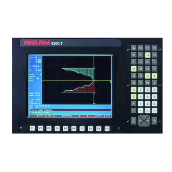
4200T CNC Programming and Operations Manual P/N 70000412F - CNC Console and Software Basics Section 2 - CNC Console and Software Basics CNC Console Refer to Figure 2-1. The CNC console consists of a 14-inch color screen and two keypads: one to the right of the screen and the other one underneath. -
Page 23: Keypad
4200T CNC Programming and Operations Manual P/N 70000412F - CNC Console and Software Basics Keypad Refer to Figure 2-2. The keypad to the right of the monitor is laid out in two groups. Alphanumeric Keys Editing Keys Figure 2-2, Keypad Keys All rights reserved. -
Page 24: Alphanumeric Keys
4200T CNC Programming and Operations Manual P/N 70000412F - CNC Console and Software Basics Alphanumeric Keys Refer to Figure 2-2, Keypad Keys. Alphanumeric Keys enable you to key-in position coordinates (X and Z) and program G, M, S and T codes. - Page 25 4200T CNC Programming and Operations Manual P/N 70000412F - CNC Console and Software Basics Key Face Primary Function Shift Function Letter R Underscore Letter S/Spindle Speed Backslash Designator Letter T/Tool words Single Quote Letter U None Letter V Question Mark...
-
Page 26: Editing Keys
4200T CNC Programming and Operations Manual P/N 70000412F - CNC Console and Software Basics Editing Keys Refer to Table 2-2. Use the editing keys to edit programs and move around the screen. Table 2-2, Editing Keys Label or Key Face... -
Page 27: Soft Keys
4200T CNC Programming and Operations Manual P/N 70000412F - CNC Console and Software Basics Table 2-3, Programming Word Keys (Continued) Label or Name Key Face Function POSITIVE/NEGATIVE Used to indicate positive or INDICATOR negative direction or value, plus or minus; in Manual Data Input (MDI) mode, press key to insert a minus (-) sign. -
Page 28: Pop-Up Menus
4200T CNC Programming and Operations Manual P/N 70000412F - CNC Console and Software Basics Pop-up Menus Refer to Figure 2-3. Pop-up menus are temporary menus that enable you to make additional selections. Pop-up menus automatically appear where needed. Each pop-up menu contains a highlight bar. Use the keys to move the highlight bar up and down the menu. -
Page 29: Typeover And Insert Modes
4200T CNC Programming and Operations Manual P/N 70000412F - CNC Console and Software Basics Typeover and Insert Modes The edit mode has two text entry modes: “typeover” and “insert”. By default, the CNC runs in the typeover mode. In the typeover mode, new characters replace characters marked by the cursor (the white underline). - Page 30 4200T CNC Programming and Operations Manual P/N 70000412F - CNC Console and Software Basics Messages Figure 2-4, Message Window All rights reserved. Subject to change without notice. 31-July-05...
-
Page 31: Manual Panel
4200T CNC Programming and Operations Manual P/N 70000412F - Manual Operation and Machine Setup Section 3 - Manual Operation and Machine Setup This section describes the functions of the keys and switches on the Manual Panel. It also provides information on manual operations. -
Page 32: Manual Panel Keys
4200T CNC Programming and Operations Manual P/N 70000412F - Manual Operation and Machine Setup Manual Panel Keys Manual Operation Keys enable you to control machine movements manually. These keys are located on the Manual Panel. See Table 3-1. Table 3-1, Manual Operation Keys... -
Page 33: Manual Panel Leds
4200T CNC Programming and Operations Manual P/N 70000412F - Manual Operation and Machine Setup Table 3-1, Manual Operation Keys (Continued) Label or Name Key Face Purpose JOG + Moves selected axis in positive direction. Used in all Jog modes. Feedrate determined by machine builder. -
Page 34: Manual Mode Screen
4200T CNC Programming and Operations Manual P/N 70000412F - Manual Operation and Machine Setup Manual Mode Screen Refer to Figure 3-2. When the CNC is in Manual Mode, it displays the Manual screen. The Manual screen is the first screen displayed when you turn on the CNC. -
Page 35: Machine Status Display Area Labels
4200T CNC Programming and Operations Manual P/N 70000412F - Manual Operation and Machine Setup Distance To Go Displays distance to go with respect to X and Z commanded coordinates. Machine Status Display Area Displays operating information. Active Soft Key Refer to Table 3-2. Soft key functions change from screen to screen. -
Page 36: Program Area Labels
4200T CNC Programming and Operations Manual P/N 70000412F - Manual Operation and Machine Setup DWELL: A timed pause, indicated in number of seconds or revolutions. Units are specified as seconds or revolutions, during builder setup. OVERRIDE: Indicates whether the feedrate override setting applies to both feed and rapid moves or to feed moves only. -
Page 37: Shutting Down The Cnc
4200T CNC Programming and Operations Manual P/N 70000412F - Manual Operation and Machine Setup Shutting Down the CNC To shut down the CNC: 1. Press The servos disengage and the CNC reverts to Manual STOP. Mode. 2. Press SHIFT (F10). The CNC displays the Software Options menu. -
Page 38: Activating Manual Mode Rapid Or Feed
4200T CNC Programming and Operations Manual P/N 70000412F - Manual Operation and Machine Setup Before you make a manual move, make any necessary mode settings. Modes set from the Manual screen remain active if the CNC is put in a program operating mode until the mode is changed by the program or operator. -
Page 39: Adjusting Rapid Move Speed
4200T CNC Programming and Operations Manual P/N 70000412F - Manual Operation and Machine Setup When the is set to 100%, the CNC makes all Feed FEEDRATE OVERRIDE moves at the programmed feedrate. To run the CNC at a percentage of the programmed feedrate, adjust the . -
Page 40: Setting Absolute Zero
4200T CNC Programming and Operations Manual P/N 70000412F - Manual Operation and Machine Setup Setting Absolute Zero Refer to Figure 3-3. In Absolute Mode, all positions are measured from Absolute Zero. Absolute Zero is the point the CNC recognizes as X0, Z0 when the Absolute Positioning Mode is active. -
Page 41: Jog Moves
4200T CNC Programming and Operations Manual P/N 70000412F - Manual Operation and Machine Setup When the machine is powered up, its present location is automatically set as the Absolute Zero Reference. When the CNC is shut down, the position of the Absolute Zero Reference is lost. -
Page 42: Jogging The Machine (In Increments)
4200T CNC Programming and Operations Manual P/N 70000412F - Manual Operation and Machine Setup Jogging the Machine (in Increments) In Manual Mode, you can position the machine with jog increments. Jog increments advance the machine in selected increments: 1, 10, or 100 times the machine resolution. -
Page 43: Using Manual Data Input Mode
Operating a Handwheel Mounted on the Manual Panel In some 4200T systems, one handwheel is mounted on the Manual Panel. In Manual Mode, you can use the handwheel to jog any controlled axis (X or Z). The machine builder must enable the handwheel option in the Setup Utility. -
Page 44: Operating Handwheels Mounted On The Machine
4200T CNC Programming and Operations Manual P/N 70000412F - Manual Operation and Machine Setup Refer to Table 3-4 for selections available with the handwheel. Table 3-4, Handwheel Jog Resolution Settings Jog Mode Setting Handwheel Resolution FEED Not Available RAPID Not Available... -
Page 45: Preparatory Functions: G-Codes
4200T CNC Programming and Operations Manual P/N 70000412F - Preparatory Functions: G-Codes Section 4 - Preparatory Functions: G-Codes Preparatory Functions: G-Codes G-codes initiate motion commands, canned cycles, various machine functions and other CNC capabilities. More than one G-code may be specified per block. - Page 46 4200T CNC Programming and Operations Manual P/N 70000412F - Preparatory Functions: G-Codes Table 4-1, Modal and Non-Modal G-Codes Modal Non-Modal G-Code Function G-Code Function Positioning-Rapid Traverse Dwell Linear Interpolation Ellipse Circular Interpolation-CW Exact Stop Check Circular Interpolation-CCW Probe Move Stored Stroke Limit ON...
-
Page 47: Rapid Traverse (G0)
4200T CNC Programming and Operations Manual P/N 70000412F - Preparatory Functions: G-Codes Rapid Traverse (G0) Format: G0 initiates rapid traverse. The machine builder sets the actual rapidrate in the Setup Utility. Use rapid traverse to position the tool prior to or after a cut. -
Page 48: Linear Interpolation (G1)
4200T CNC Programming and Operations Manual P/N 70000412F - Preparatory Functions: G-Codes Linear Interpolation (G1) Format: Linear Interpolation (G1) initiates feed motion in a straight line. It is used for cutting a part. Straight-line motion can be linear or angular. The block could contain any combination of the available axes. -
Page 49: Angular Motion Programming Example
4200T CNC Programming and Operations Manual P/N 70000412F - Preparatory Functions: G-Codes Angular Motion Programming Example Angular (vectored) motions are straight-line motions involving motion in both the X- and Z-axes. They require two dimensions (X and Z) to define the endpoint of motion. Table 4-4 demonstrates how G1 is used in a program. -
Page 50: Circular Interpolation (G2 And G3)
4200T CNC Programming and Operations Manual P/N 70000412F - Preparatory Functions: G-Codes Circular Interpolation (G2 and G3) Arc input format: G2 (G3) Xn Zn In Kn Radius format: G2 (G3) Xn Zn Rn Circular Interpolation initiates circular moves, including arcs. Table 4-5 contains the parameters necessary to program these moves. - Page 51 4200T CNC Programming and Operations Manual P/N 70000412F - Preparatory Functions: G-Codes Examples of Circular Interpolation Refer to Table 4-6 and Figure 4-4. Both the MM and Inch equivalents are provided. Table 4-6, Circular Interpolation in Absolute Mode, Inches (MM)
-
Page 52: Partial Arcs
4200T CNC Programming and Operations Manual P/N 70000412F - Preparatory Functions: G-Codes Table 4-7 provides the incremental version of the part program diagrammed in Figure 4-4, Circular Interpolation. Table 4-7, Circular Interpolation in Incremental Mode, Inches (MM) G70 (G71) G90 G1 X0 Z0 Activate Inch and Absolute G95 F.010 (25.4) -
Page 53: Ellipse (G5)
Block 21 commands an infinite dwell. The time or revolution countdown is displayed in the Machine Status area of the Manual screen. NOTE: ANILAM recommends that you use the Programmed Stop M- code (M00) instead of G4T0. Ellipse (G5) Format: G5 Xn Zn ln Kn An Bn Ln Use G5 to program a full or partial ellipse. -
Page 54: Non-Modal Exact Stop Check (G9)
4200T CNC Programming and Operations Manual P/N 70000412F - Preparatory Functions: G-Codes Non-modal Exact Stop Check (G9) Format NOTE: Rapid moves are always performed in In-Position Mode. Refer to Table 4-9 for a list of G-codes related to Exact Stop Check (G9). -
Page 55: Setting Software Limits (G22)
4200T CNC Programming and Operations Manual P/N 70000412F - Preparatory Functions: G-Codes Setting Software Limits (G22) Format: G22 Xn Zn In Kn Activates Software Limits, Modal Format: Cancels Software Limits and allows free movement within the machine limits. Refer to Table 4-10. -
Page 56: Maximum Spindle Speed (G24)
4200T CNC Programming and Operations Manual P/N 70000412F - Preparatory Functions: G-Codes Figure 4-5, Front Tooling Software Limits Figure 4-6, Rear Tooling Software Limits Maximum Spindle Speed (G24) Format: G24 Sxxxx Refer to Table 4-11. Table 4-11, G24 Address Words... -
Page 57: Probe Move (G31)
4200T CNC Programming and Operations Manual P/N 70000412F - Preparatory Functions: G-Codes The S-word can contain up to four digits (Sxxxx, range 0001 to 9999). Leading zeros can be omitted. Once you program a G24 command, the CNC prevents the programmed spindle speed from exceeding the entered amount (Sxxxx). -
Page 58: Offsets (Work Coordinate System Select) (G53)
4200T CNC Programming and Operations Manual P/N 70000412F - Preparatory Functions: G-Codes Refer to Table 4-13 for a sample Program Listing containing the G33 command. E or F, not both, must be programmed. At least one axis address must accompany F/E value. F (pitch) is usually used in MM programming. - Page 59 4200T CNC Programming and Operations Manual P/N 70000412F - Preparatory Functions: G-Codes Notes: 1. All of the above will clear any G92 active Tool Table. 2. Typically, the table found in the Tool Table is used (F1) to set the values and the values activated in the part program by programming G53 with O# (such as G53 O1).
-
Page 60: Modal Corner Rounding/Chamfering (G59)
4200T CNC Programming and Operations Manual P/N 70000412F - Preparatory Functions: G-Codes Changing Fixture Offsets Using Calibrate Keys To change offset using the calibrate keys: 1. Move the machine to the desired position. 2. Highlight the offset. 3. Press CalibX. - Page 61 4200T CNC Programming and Operations Manual P/N 70000412F - Preparatory Functions: G-Codes Figure 4-8, G59 Part Program Refer to Figure 4-8. The diagram illustrates the part programmed in Table 4-15. In this example, G59 is used to command modal corner rounding.
-
Page 62: Cancel Modal Corner Rounding (G60)
4200T CNC Programming and Operations Manual P/N 70000412F - Preparatory Functions: G-Codes To change the radius between intersections, refer to the previous program. If you wanted to change the radius of the corner rounding of N45 to R0.25, you would need to insert a G59 command (G59 R0.25) between lines N40 and N45. -
Page 63: Contouring Mode (Cutting Mode) (G64)
4200T CNC Programming and Operations Manual P/N 70000412F - Preparatory Functions: G-Codes While the In-Position Mode (G61) is active, the CNC approaches target and performs an in-position check before the next move is executed. The CNC comes to a complete stop at the completion of each command. This could cause tool dwell marks to appear on the workpiece, but prevents the CNC from rounding off sharp corners. -
Page 64: Using Macros (G65, G66, G67)
4200T CNC Programming and Operations Manual P/N 70000412F - Preparatory Functions: G-Codes Using Macros (G65, G66, G67) NOTE: Before using macros, you must learn how variables and parameters are used in a program or subprogram. Refer to “Section 16 - Advanced Programming Features”... - Page 65 4200T CNC Programming and Operations Manual P/N 70000412F - Preparatory Functions: G-Codes A subprogram consists of fixed dimensions, but a macro contains variables and parameters that can change every time the macro is used. Macros can be stored in the same file as the main program or in a separate file.
-
Page 66: Inch Mode (G70) Or Mm Mode (G71)
4200T CNC Programming and Operations Manual P/N 70000412F - Preparatory Functions: G-Codes Inch Mode (G70) or MM Mode (G71) Inch Mode Format: G70 MM Mode Format: You can change the unit of measurement display via the Inch Mode (G70) or MM Mode (G71) commands. G70 switches the CNC to Inch Mode. - Page 67 4200T CNC Programming and Operations Manual P/N 70000412F - Preparatory Functions: G-Codes ABSINC Figure 4-9, Absolute vs. Incremental Programming Table 4-24, Absolute vs. Incremental Programming Examples Absolute Incremental Point 1 Point 2 Z-.1 Point 3 X1.0 Point 4 Point 5 Z-1.6...
-
Page 68: Presetting The Axes (G92)
Homes X and Z-axes. N03 G92 X4 Z6 Sets current position to X4, Z6. NOTE: Anilam recommends that you do not use G92 to set Part Zero. If the machine loses power, this reference point will be lost. 4-24 All rights reserved. Subject to change without notice. -
Page 69: Cutting Feedrates In Feed Per Minute (G94)
4200T CNC Programming and Operations Manual P/N 70000412F - Preparatory Functions: G-Codes Cutting Feedrates in Feed per Minute (G94) G94: (FPM) Inch or MM per minute feedrate programming. Refer to Table 4-27. Feedrates programmed in Feed Per Minute (FPM) (G94) are either in Inch (G70) or MM (G71) Mode. In FPM Mode, the moves are made at a specified rate per minute. -
Page 70: Setting Spindle Speed To Constant Surface Speed (G96)
4200T CNC Programming and Operations Manual P/N 70000412F - Preparatory Functions: G-Codes Setting Spindle Speed to Constant Surface Speed (G96) CAUTION: Program a G24 Sxxxx (Maximum Spindle RPM) prior to G96. This prevents the RPM of the spindle from reaching maximum speed when a move to the centerline (X0) is programmed. -
Page 71: Programming A Z-Axis Turning/Boring Cycle With A Defined Profile (G73)
4200T CNC Programming and Operations Manual P/N 70000412F - Canned Cycles Section 5 - Canned Cycles Programming a Z-Axis Turning/Boring Cycle with a Defined Profile (G73) Format G73 Wn An Rn Sn Cn Bn Pn In Jn Kn Refer to Table 5-1. The table lists the Address Words that define the G73 (longitudinal) and G74 (radial) area clearance cycles. - Page 72 4200T CNC Programming and Operations Manual P/N 70000412F - Canned Cycles The subprogram profile is programmed after the end of the main program and uses the letter O. The profile program can contain lines, arcs and angles. You can use the shape editor. An optional finish pass removes the finish stock amount defined by parameters R (X) and S (Z).
- Page 73 4200T CNC Programming and Operations Manual P/N 70000412F - Canned Cycles Table 5-2, G73 Part Program Program Block Description N1 G70 G90 G0 X0 Z0 T0 Sets Inch/MM Mode and Absolute Mode. Places machine at X0,Z0 with no tool offsets active.
-
Page 74: Programming An X-Axis Facing/Boring Cycle With Defined Profile (G74)
4200T CNC Programming and Operations Manual P/N 70000412F - Canned Cycles Programming an X-Axis Facing/Boring Cycle with Defined Profile (G74) Format G74 Wn An Rn Sn Cn Bn Pn In Jn Kn Refer to Table 5-1, G73 and G74 Address Words. - Page 75 4200T CNC Programming and Operations Manual P/N 70000412F - Canned Cycles 0.60 Dia. (82.55MM) 0.2" R. 2 places (5.08 MM) 3.25" Dia. (82.55MM) 0.10" X 45 deg. CHAMFER (2.54MM) 0.05" X 45 deg. 0.40" CHAMFER (10.16MM) (1.27MM) 0.70" (17.78MM) 74-2 Figure 5-4, G74 Part Program Refer to Figure 5-4.
- Page 76 4200T CNC Programming and Operations Manual P/N 70000412F - Canned Cycles The following subprogram describes the part profile called into the main program above. The CNC calculates actual moves based on the profile described in the subroutine. N7 O8 (Subprogram) Establishes name of Subprogram (O8).
-
Page 77: Programming A Z-Axis Rough Turning Or Boring Cycle (G76)
4200T CNC Programming and Operations Manual P/N 70000412F - Canned Cycles Programming a Z-Axis Rough Turning or Boring Cycle (G76) Use the Z-Axis Rough Turning Cycle (G76) to clear stock along the Z-axis (outer diameter, O.D.) or to bore a hole (inner diameter, I.D.). Refer to Table 5-4 for a list and description of the Address Words associated with G76. - Page 78 4200T CNC Programming and Operations Manual P/N 70000412F - Canned Cycles G81 Address Words Refer to Figure 5-5. The G76 turning cycle removes stock material along the Z-axis, from the outer diameter of the work. The tool must be positioned appropriately before the canned cycle begins.
-
Page 79: Programming An X-Axis Radial (Facing) Roughing Cycle (G77)
4200T CNC Programming and Operations Manual P/N 70000412F - Canned Cycles Programming an X-Axis Radial (Facing) Roughing Cycle (G77) Format: G77 Xn Zn Cn An Bn Dn En Refer to Table 5-5 for a list and description of the Address Words used to define G77. - Page 80 4200T CNC Programming and Operations Manual P/N 70000412F - Canned Cycles G77 can be used for I.D. or O.D cuts. B determines the standoff position in Z, from which the tool advances to the start of the facing cycle. The CNC calculates the depth of each pass and the number of passes necessary to reach finish depth (Z).
-
Page 81: Programming A Pecking Cycle (G78)
4200T CNC Programming and Operations Manual P/N 70000412F - Canned Cycles Programming a Pecking Cycle (G78) Format G78 Zn Rn Fn In Pn Refer to Table 5-6 for a list and description of the Address Words used to define a Pecking Cycle (G78). -
Page 82: Programming A Chip Break Cycle (G79)
4200T CNC Programming and Operations Manual P/N 70000412F - Canned Cycles Programming a Chip Break Cycle (G79) Format G79 Zn Rn Fn In Jn Kn Wn Un Pn Refer to Table 5-7 for a list and description of the Address Words used to define a Chip Break Cycle (G79). -
Page 83: Programming A Longitudinal Grooving Cycle (G81)
4200T CNC Programming and Operations Manual P/N 70000412F - Canned Cycles The peck distance will never be more than I or less than K. To prevent binding of the chips, tool, and workpiece in deep-hole drilling, as the depth increases, the peck distance (J) decreases. The retract depth (U) variable allows the programmer to fully retract the tool from the hole, at specified incremental depths. - Page 84 4200T CNC Programming and Operations Manual P/N 70000412F - Canned Cycles After the tool reaches total depth (X), it remains at the bottom of the groove until the dwell time (D, optional) elapses. The CNC calculates the number and width of passes from the total length (Z) required and the tool width (W).
-
Page 85: Programming A Radial Grooving Cycle (G82)
4200T CNC Programming and Operations Manual P/N 70000412F - Canned Cycles Table 5-9, G81 Programming Example Program Block Description N1 O7 *GROOVY Establishes program name and number. N2 G90 G70 G0 T0 X0 Z0 M5 Sets Absolute/Inch/Rapid Modes. Cancels tool offsets and positions tool at X0, Z0. - Page 86 4200T CNC Programming and Operations Manual P/N 70000412F - Canned Cycles Tool Path Part Outline X0, Z0 Figure 5-12, G82 Address Words Refer to Figure 5-12. The G82 canned cycle creates a groove along the radial (X) axis. Use a groove-cutting tool for this cycle. The cycle has built-in compensation for tool width.
-
Page 87: Types Of Threading
4200T CNC Programming and Operations Manual P/N 70000412F - Canned Cycles Types of Threading Refer to Table 5-11. The following terms will help explain the threading cycles given in subsequent sections. Table 5-11, Types of Threading Threading Description Compound Threading The tool enters the work on an angle (A) specified by the programmer. -
Page 88: Cutting Longitudinal Threads With Canned Cycles (G83, Uni-Directional)
4200T CNC Programming and Operations Manual P/N 70000412F - Canned Cycles Cutting Longitudinal Threads with Canned Cycles (G83, Uni-directional) Format G83 En Zn Cn Dn An Sn Rn Xn Vn Bn Wn Refer to Table 5-12 for a list and description of the Address Words used to define a Uni-directional Longitudinal Threading Cycle (G83). - Page 89 4200T CNC Programming and Operations Manual P/N 70000412F - Canned Cycles Refer to Figure 5-13. The figure describes the motion of the CNC during a G83 canned cycle. The G83 canned cycle creates a longitudinal thread along the Z-axis, utilizing multiple-pass threading. G83 supports an X-axis taper distance or angle.
-
Page 90: Cutting Longitudinal Threads With Canned Cycles (G84, Bi-Directional)
4200T CNC Programming and Operations Manual P/N 70000412F - Canned Cycles Cutting Longitudinal Threads with Canned Cycles (G84, Bi-directional) Format G84 En (Fn) Zn Cn Dn An Sn Rn Bn Wn Refer to Table 5-13 for a list and description of the Address Words used to define a Bi-directional Longitudinal Threading Cycle (G84). - Page 91 4200T CNC Programming and Operations Manual P/N 70000412F - Canned Cycles Refer to Figure 5-14. The figure describes the motion of the CNC during a G84 canned cycle. The G84 canned cycle creates a longitudinal thread along the Z-axis, utilizing multiple-pass threading. G84 does not support an X-axis taper distance or angle, but allows bi-directional threading.
- Page 92 4200T CNC Programming and Operations Manual P/N 70000412F - Canned Cycles G84 Programming Example Figure 5-15, G84 Programming Example Refer to Figure 5-15 for a diagram of the part programmed in Table 5-14. The Listing provides a sample Program Listing for a G84 threading canned cycle.
-
Page 93: Cutting Radial Threads With Canned Cycles (G85, Uni-Directional)
4200T CNC Programming and Operations Manual P/N 70000412F - Canned Cycles Cutting Radial Threads with Canned Cycles (G85, Uni-directional) Format: G85 En (Fn) Xn Cn Dn An Sn Rn Zn Vn (Bn) Wn Refer to Table 5-15 for a listing and description of Address Words associated with the G85 comman7d. - Page 94 4200T CNC Programming and Operations Manual P/N 70000412F - Canned Cycles tool path part edge Figure 5-16, G85 Canned Cycle NOTE: All variables are sign (+/-) dependent. Moves can be defined as Outer Diameter/Inner Diameter, and toward or away from the chuck or part centerline.
- Page 95 4200T CNC Programming and Operations Manual P/N 70000412F - Canned Cycles G85 Radial (Face) Plunge Thread Example SCROLL THD PITCH = 0.125" (3MM) X0, Z0 4.00" (101.6MM) 1.40" (35.56MM) .20" (5.08MM) G85-B Figure 5-17, Radial (Face) Threading Example Refer to Figure 5-17 . The figure shows a part diagram for a G85 cycle.
-
Page 96: Cutting Radial Threads With Canned Cycles (G86, Bi-Directional)
4200T CNC Programming and Operations Manual P/N 70000412F - Canned Cycles Cutting Radial Threads with Canned Cycles (G86, Bi-directional) Format G86 En (Fn) Xn Cn Dn An Sn Rn Bn Wn Refer to Table 5-17 for a listing and description of the Address Words associated with the G86 canned cycle. - Page 97 4200T CNC Programming and Operations Manual P/N 70000412F - Canned Cycles Refer to Figure 5-18 . The diagram describes the motion of the CNC during the G86, multiple-pass thread cutting. In Radial Bi-directional threading (G86), passes are performed along the X-axis (face). G86 is designed for compound threading.
-
Page 98: Tapping A Hole With A Canned Cycle (G87)
4200T CNC Programming and Operations Manual P/N 70000412F - Canned Cycles Tapping a Hole with a Canned Cycle (G87) NOTE: The machine must support spindle M-codes (spindle forward, spindle reverse and spindle off) in order to use this cycle. Format... - Page 99 4200T CNC Programming and Operations Manual P/N 70000412F - Canned Cycles Refer to Figure 5-19 . The diagram describes the Address Words used to define a G87 Tapping Cycle. G87 is used for tapping holes. The CNC feeds from the retract plane to the depth of the hole in Z. The spindle stops and reverses motion, and retracts the tool from the hole.
-
Page 100: Programming A Boring Cycle (G88)
4200T CNC Programming and Operations Manual P/N 70000412F - Canned Cycles Programming a Boring Cycle (G88) Format G88 Zn Xn Cn An Bn Refer to Table 5-19 for a listing and description of the Address Words associated with the G88 canned cycle. - Page 101 4200T CNC Programming and Operations Manual P/N 70000412F - Canned Cycles Refer to Figure 5-20 . The G88 boring cycle removes stock material along the Z-axis, from the inner diameter of the work. The tool must be positioned appropriately before the canned cycle begins. Perform boring cycles only on a workpiece that has been pre-drilled.
-
Page 102: Lathe Tool Probe Cycles (Option)
Lathe Tool Probe Cycles (Option) This document describes operation and an overview of the lathe tool probe canned cycles available on the 4200T CNC product. Probing is an option on the 4200T CNC. The cycles provided perform the most common tool probing functions. Custom cycles to perform specific functions can be written using the G31 primitive and parametric programming. -
Page 103: Tool Probe G-Code Cycle Designations
4200T CNC Programming and Operations Manual P/N 70000412F - Canned Cycles Tool Probe G-code Cycle Designations Before running any of these probing cycles you must go into Probing Setup and set the probing setup parameters. G150 Tool Probe Calibration Cycle This is used to set the X and Z datum for diameter, length, and establish the center of the probe stylus. - Page 104 4200T CNC Programming and Operations Manual P/N 70000412F - Canned Cycles To set the Probe Parameters: • On the Software Options menu, select Software Utility. • On the Setup Options menu, select Builder Setup. • On the Builder Setup menu, select Probing.
-
Page 105: Probe Orientation
4200T CNC Programming and Operations Manual P/N 70000412F - Canned Cycles Probe Orientation Probe orientation is the position the tool is placed. G146 may be used to position the tool. If orientation 2 is to be used, the tool would be placed at the back right corner of the stylus at the appropriate distance from X and Z. - Page 106 4200T CNC Programming and Operations Manual P/N 70000412F - Canned Cycles G151 Tool Preset Cycle Bring the probe arm down and jog the tool into the orientation position. The tool that is being set must be active before calling this cycle.
-
Page 107: Description Of Tool Probe Cycles
4200T CNC Programming and Operations Manual P/N 70000412F - Canned Cycles Description of Tool Probe Cycles This section contains detailed descriptions of the tool probe cycles: • Establishing a Position on the Machine • Tool Probe Calibration Cycle ( G150 ) •... - Page 108 4200T CNC Programming and Operations Manual P/N 70000412F - Canned Cycles Tool Probe Calibration Cycle (G150) Format: G150 An Bn Sn Dn This cycle is used to calibrate the probe. This is used to set the X and Z datums establishing the center of the probe stylus and the effective probe stylus size for setting tool diameter registers.
- Page 109 4200T CNC Programming and Operations Manual P/N 70000412F - Canned Cycles Tool Preset (G151) Format: G151 Bn Cn Sn Dn This tool preset ( G151 ) can be run from within a program or from the manual mode. Refer to Table 5-21 .
- Page 110 4200T CNC Programming and Operations Manual P/N 70000412F - Canned Cycles Tool Wear/Breakage Cycle (G154) Format: G154 Bn Cn Sn Dn In Kn Un Refer to Table 5-22 . Table5-22, G154 Address Word Address Word Description (Distance away) The distance away from the probe stylus.
- Page 111 4200T CNC Programming and Operations Manual P/N 70000412F - Canned Cycles Protected Probe Positioning Cycle (G146) Format: G146 Xn Zn Fn When an X and Z move is programmed using the G146 (Protected Probe Positioning Cycle), the control will stop and alarm if the probe stylus is triggered before reaching the target set in the X and Z parameters.
-
Page 112: Activating The Program Editor
4200T CNC Programming and Operations Manual P/N 70000412F - Program Editor Section 6 - Program Editor Activating the Program Editor Program blocks are written with the Program Editor. Activate the Program Editor to put the CNC in Edit Mode. You must create program files before you can write or edit programs. - Page 113 4200T CNC Programming and Operations Manual P/N 70000412F - Program Editor Program Listing First Block Soft Keys Softkeys Status Line Figure 6-1, Edit Screen Refer to Figure 6-1 to write and edit programs from the Edit Screen. Refer to Table 6-1 for an overview of the Edit screen.
-
Page 114: Edit Soft Keys
4200T CNC Programming and Operations Manual P/N 70000412F - Program Editor Edit Soft Keys Refer to Table 6-2 for a list of the soft keys in the edit mode. Table 6-2, Edit Soft Keys Soft Key Label Function Help Activates Edit Help Menu. -
Page 115: Editing Shift Soft Keys
4200T CNC Programming and Operations Manual P/N 70000412F - Program Editor Editing Shift Soft Keys The Edit screen contains ten soft keys when it activates. Four additional soft keys activate when you press . Refer to Table 6-3 for a list of SHIFT shift soft keys in the edit mode. -
Page 116: Deleting A Program Block
4200T CNC Programming and Operations Manual P/N 70000412F - Program Editor Deleting a Program Block There are two ways to delete program blocks from a Program Listing: Press DelBlk (F4) to delete one block at a time. Use the BLOCK Operations Delete feature to delete several blocks at a time. -
Page 117: Going To A Line Of The Program Listing
4200T CNC Programming and Operations Manual P/N 70000412F - Program Editor Going to a Line of the Program Listing The Go to Line feature enables you to go to any line in the Program Listing. Go to Line operates independently of block numbering. Blocks can be numbered sequentially by any increment (1, 5, 10...). -
Page 118: Searching The Program Listing For Selected Text
4200T CNC Programming and Operations Manual P/N 70000412F - Program Editor Searching the Program Listing for Selected Text Use the Find Word and Find Next features to search blocks for selected text. Enter the text to be found. The CNC searches out the first (Find Word) and subsequent occurrences (Find Next) in the Program Listing. -
Page 119: Restoring A Block
4200T CNC Programming and Operations Manual P/N 70000412F - Program Editor Restoring a Block If a block has been deleted, you can restore it to the program by using Undelete Block. The last block deleted is the first block restored. There... -
Page 120: Abbreviating Statements
4200T CNC Programming and Operations Manual P/N 70000412F - Program Editor If Yes (F1) or No (F2) is chosen, the CNC replaces (F1) or leaves the text unchanged (F2), then moves to the next occurrence of the entered text. The Change Word feature deactivates when all occurrences of the text have been found or if you press Only (F4). -
Page 121: Marking (Highlighting) Programming Blocks
4200T CNC Programming and Operations Manual P/N 70000412F - Program Editor Marking (Highlighting) Programming Blocks Many editing features require you to mark (highlight) affected program blocks before the edit is performed. To mark program blocks: 1. In Edit Mode, place the insertion point at the beginning of the first block to be marked. -
Page 122: Copying Program Blocks
4200T CNC Programming and Operations Manual P/N 70000412F - Program Editor Copying Program Blocks NOTE: You can cut, save and paste blocks within a Program Listing. Paste features works for pasting blocks between two different programs as long as you don’t exit the editor. Use the Edit Program or Pick Program to edit another program within the editor. -
Page 123: Printing A Portion Of A Program
4200T CNC Programming and Operations Manual P/N 70000412F - Program Editor 6. Highlight BLOCK operations, and press . The BLOCK ENTER operations Pop-Up Menu activates. 7. Highlight Cut, and press . The CNC saves the blocks in ENTER memory and deletes the original blocks from the Program Listing. -
Page 124: Numbering (Or Re-Numbering) Program Blocks
4200T CNC Programming and Operations Manual P/N 70000412F - Program Editor Numbering (or Re-numbering) Program Blocks To number or re-number blocks in a program: 1. In Edit Mode, mark all the blocks in the program. 2. Press Editing (F8). The soft key highlights and the EDITING Pop-Up Menu activates. -
Page 125: Reading A Program Into Another Program
4200T CNC Programming and Operations Manual P/N 70000412F - Program Editor NOTE: The Write feature does not use or overwrite information in the buffer, where cut and saved blocks are stored. When Write is used, the information in the buffer remains unchanged. -
Page 126: Playing Recorded Keystrokes
4200T CNC Programming and Operations Manual P/N 70000412F - Program Editor Playing Recorded Keystrokes The Play keys feature retrieves recorded keystrokes and prints them on the screen. To retrieve recorded keystrokes: 1. In Edit Mode, press Misc (F9). The soft key highlights and the MISC Pop-Up Menu activates. -
Page 127: Accessing The Most Recently Used Programs
4200T CNC Programming and Operations Manual P/N 70000412F - Program Editor 5. Press Continue (F10) to return to the Edit screen. NOTE: While the program is printing, press Cancel (F9) to cancel the print job. Accessing the Most Recently Used Programs Use the Pick Program feature, from the MISC Pop-Up Menu, to access and display any of the last ten programs opened in the Edit Mode. -
Page 128: Canceling Unsaved Edits
4200T CNC Programming and Operations Manual P/N 70000412F - Program Editor Canceling Unsaved Edits If edits have not been saved, they can be canceled. To cancel unsaved edits: 1. In Edit Mode, press and then press Quit ( + F10). - Page 129 4200T CNC Programming and Operations Manual P/N 70000412F - Edit Help Section 7 - Edit Help Edit Help provides diagrams and entry fields to program move types and canned cycles for blueprint programming. NOTE: To select menu items (2 through 9, +/-, or .), press the key corresponding to the desired item, and then press .
- Page 130 4200T CNC Programming and Operations Manual P/N 70000412F - Edit Help LINES ARCS RAD/CHAMFER MUT IPLE T HREADING CLEARING COMPENS AT ION DRILL/T AP GENERAL Feed/Rev. Feed/Min. Inc r. G70 G90 G0 G95 X0 Z0 F .006 T 0 Absolute X1.0 Z0.1 T 1...
- Page 131 4200T CNC Programming and Operations Manual P/N 70000412F - Edit Help Soft Keys Figure 7-2, Main Edit Help Menu Soft Keys Figure 7-3, Sample Help Template Menu All rights reserved. Subject to change without notice. 31-July-05...
-
Page 132: Edit Help Menu
4200T CNC Programming and Operations Manual P/N 70000412F - Edit Help Edit Help Menu Main Edit Help Menu (Figure 7-2) displays categories for which Help Menus are available. Refer to Table 7-2, Edit Help Menu Features for a description of Main Edit Help Menu features. - Page 133 4200T CNC Programming and Operations Manual P/N 70000412F - Edit Help Table 7-2, Edit Help Menu Features Feature Description Menu Item Number Use this number to select a menu item. Help Templates In the Edit Help Menu, help templates access template help menus.
- Page 134 4200T CNC Programming and Operations Manual P/N 70000412F - Edit Help Table 7-3, Edit Help G-Code Menu G-Code Label and Description Dwell. Programs a timed or infinite dwell. Exact Stop (Single Block). Non-modal exact stop check. Activates exact stop check for a single block.
- Page 135 4200T CNC Programming and Operations Manual P/N 70000412F - Edit Help Table 7-4, Edit Help M-Code Listing M-Code Function Program stop Optional program stop End of program Spindle ON FWD Spindle ON REV Spindle OFF Coolant ON Coolant OFF Jump to new program...
-
Page 136: Edit Help Soft Keys
4200T CNC Programming and Operations Manual P/N 70000412F - Edit Help Edit Help Soft Keys Refer to Table 7-5 for a list of the soft keys available in the Main Edit Help Menu. Table 7-5, Edit Help Soft Keys Soft Key Label Description Moves highlight to the next Help Template. -
Page 137: Help Template Menu
4200T CNC Programming and Operations Manual P/N 70000412F - Edit Help Help Template Menu Selecting a help template from the Edit Help Menu activates the Help Template Menu for the selected move type or Canned Cycle. (Refer to Figure 7-3, Sample Help Template Menu). - Page 138 4200T CNC Programming and Operations Manual P/N 70000412F - Edit Help Table 7-6, Help Template Menus (Continued) Template Description Reference Table DRILL/TAP Table 7-14, DRILL/TAP Help Template Menu (Drill and Tapping Cycles) The following features appear in each of the Help Template Menus:...
-
Page 139: Help Graphic Screens
4200T CNC Programming and Operations Manual P/N 70000412F - Edit Help Help Graphic Screens The Help Graphic screens list and give instructions on entering move types and Canned Cycles into the Program Listing. Refer to Figure 7-4. Help Graphics screens are available for templates... - Page 140 4200T CNC Programming and Operations Manual P/N 70000412F - Edit Help The following features are available in the Help Graphic screens: Menu Item Number Menu items 2 through 9 are inactive in the Help Graphic screen. A new selection can be made...
-
Page 141: Using Help Graphic Screens To Enter Program Blocks
4200T CNC Programming and Operations Manual P/N 70000412F - Edit Help Using Help Graphic Screens to Enter Program Blocks The Program Editor displays Help Graphic screens for writing and editing program blocks. When a Help Graphic screen is first displayed, the first entry field is highlighted. -
Page 142: Available Help Graphic Screens
4200T CNC Programming and Operations Manual P/N 70000412F - Edit Help Available Help Graphic Screens Help Graphic Screens are available for each of the templates shown and described in Table 7-7. The table shows the Edit Help Menu Templates and Template Menus. The input labels and entry fields are defined for each move type available in Edit Help. - Page 143 4200T CNC Programming and Operations Manual P/N 70000412F - Edit Help Table 7-8, LINES Help Template Menu LINES LINES Templates and Parameters Move Description CNC moves in a straight line along the Z-axis. Z End Pt.: Z endpoint CNC moves in a straight line along the X-axis.
- Page 144 4200T CNC Programming and Operations Manual P/N 70000412F - Edit Help Table 7-8, LINES Help Template Menu (Continued) LINES LINES Templates and Parameters Move Description CNC moves along a vectored path from ANGLE/RADIUS the current location to the endpoint. Angle: B, angle measured from the Z-axis (3 o’clock equals 0 degrees).
- Page 145 4200T CNC Programming and Operations Manual P/N 70000412F - Edit Help Table 7-9, ARCS Help Template Menu ARCS Templates and Parameters Move Description CNC moves along a radial path from the RADIUS/END current location to the programmed endpoint. X End Pt.: X endpoint Z End Pt.:...
- Page 146 4200T CNC Programming and Operations Manual P/N 70000412F - Edit Help Table 7-9, ARCS Help Template Menu (Continued) ARCS Templates and Parameters Move Description CNC moves along a radial path from the CENTER/X current location to the programmed endpoint. X Center Pt.: I, incremental centerpoint of the arc in X.
- Page 147 4200T CNC Programming and Operations Manual P/N 70000412F - Edit Help Table 7-9, ARCS Help Template Menu (Continued) ARCS Templates and Parameters Move Description CNC performs an arc move into another ARC/ARC arc move. The first arc ends and the second arc begins at the point where the two arcs are tangent.
- Page 148 4200T CNC Programming and Operations Manual P/N 70000412F - Edit Help Table 7-10, RAD/CHAMFER Help Template Menu RAD/CHAMFER RAD/CHAMFER Templates and Parameters Move Description The CNC performs a LINE move to the intersecting ARC, moves around the arc, RADIUS and then moves along the second LINE to the specified endpoints.
- Page 149 4200T CNC Programming and Operations Manual P/N 70000412F - Edit Help Table 7-10, RAD/CHAMFER Help Template Menu (Continued) RAD/CHAMFER RAD/CHAMFER Templates and Parameters Move Description The CNC performs an automatic corner CORNER CHAMF chamfer (where practical) at all intersecting elements (LINES, ARCS).
- Page 150 4200T CNC Programming and Operations Manual P/N 70000412F - Edit Help Table 7-11, MULTIPLE Help Template Menu MUTIPLE MULTIPLE Templates and Parameters Move Description The CNC performs a LINE move DEFINITION along the First Angle to the intersection of the Second Angle,...
- Page 151 4200T CNC Programming and Operations Manual P/N 70000412F - Edit Help Table 7-11, MULTIPLE Help Template Menu (Continued) MUTIPLE MULTIPLE Templates and Parameters Move Description The CNC performs a LINE move RAD/RAD along the 1st Angle to the intersecting arc. After completing...
- Page 152 4200T CNC Programming and Operations Manual P/N 70000412F - Edit Help Table 7-11, MULTIPLE Help Template Menu (Continued) MUTIPLE MULTIPLE Templates and Parameters Move Description The CNC performs a LINE move CHAMF/CHAMF along the 1st Angle to the intersecting chamfer. After...
- Page 153 4200T CNC Programming and Operations Manual P/N 70000412F - Edit Help Table 7-11, MULTIPLE Help Template Menu (Continued) MUTIPLE MULTIPLE Templates and Parameters Move Description The CNC performs a LINE move CHAMF/RAD along the 1st Angle to the intersecting chamfer. After...
- Page 154 4200T CNC Programming and Operations Manual P/N 70000412F - Edit Help Table 7-12, THREADING Help Template Menu THREADING THREADING Templates and Parameters Move Description The G83 cycle creates a longitudinal thread along the Z-axis using multiple UNI-DIRECT. passes to reach full thread depth. The...
- Page 155 4200T CNC Programming and Operations Manual P/N 70000412F - Edit Help TPI: E, Threads per inch. Used in Inch programming. Lead: F, pitch (single pass threading) or amount of travel in Z per revolution (multi-pass threading). Used in MM programming.
- Page 156 4200T CNC Programming and Operations Manual P/N 70000412F - Edit Help threading Canned Cycle. Num. Starts: W, used only in multiple pass threading, the number of staggered starts used to reach depth. Default: 1. NOTE: Specifying the Num. of Starts changes the way the CNC interprets all other threading variables.
- Page 157 4200T CNC Programming and Operations Manual P/N 70000412F - Edit Help angle (described by the A parameter), Num. Starts: W, used to program the number of and cuts only on the leading edge of the starts in a multiple start thread. Default: 1 (Single tool.
- Page 158 4200T CNC Programming and Operations Manual P/N 70000412F - Edit Help Table 7-12, THREADING Help Template Menu (Continued) THREADING THREADING Templates and Parameters Move Description The CNC feeds the tap from the initial TAPPING start position (R) into a pre-drilled hole along the Z-axis.
- Page 159 4200T CNC Programming and Operations Manual P/N 70000412F - Edit Help Table 7-13, CLEARING Help Template Menu CLEARING CLEARING Templates and Parameters Move Description The G73 Area Clearance Cycle rough turns a AREA CLR TURN work piece to a profile described in a subprogram.
- Page 160 4200T CNC Programming and Operations Manual P/N 70000412F - Edit Help Table 7-13, CLEARING Help Template Menu (Continued) CLEARING CLEARING Templates and Parameters Move Description The G74 Area Clearance Cycle rough faces a AREA CLR FACE work piece to a profile described in a subprogram.
- Page 161 4200T CNC Programming and Operations Manual P/N 70000412F - Edit Help Depth/Pass: C, maximum incremental will not exceed the maximum depth of cut (C). depth of cut per side for each pass. The rear angle of the tool (E) is checked...
- Page 162 4200T CNC Programming and Operations Manual P/N 70000412F - Edit Help Table 7-13, CLEARING Help Template Menu (Continued) CLEARING CLEARING Templates and Parameters Move Description The G81 cycle creates a groove along the Z- LON'L GROOVE axis using the length (Z), and depth (X) parameters.
- Page 163 4200T CNC Programming and Operations Manual P/N 70000412F - Edit Help Table 7-14, DRILL/TAP Help Template Menu DRILL/TAP DRILL/TAP Templates and Parameters s Move Description The Pecking cycle drills a hole using a PECKING pecking action. The depth of each peck...
- Page 164 4200T CNC Programming and Operations Manual P/N 70000412F - Edit Help Table 7-14, DRILL/TAP Help Template Menu (Continued) DRILL/TAP DRILL/TAP Templates and Parameters s Move Description The G88 Boring cycle removes stock material along the Z-axis in a series of BORING passes.
-
Page 165: Programming Modal G-Codes In Edit Help
4200T CNC Programming and Operations Manual P/N 70000412F - Edit Help Programming Modal G-Codes in Edit Help Certain G-Codes define the way the CNC will interpret commands entered by an operator. These G-Codes set the CNC to interpret measurement units as Inch or Metric, numerical values as Absolute or Incremental, set tool movement to feed or rapid rate, set spindle speed to feedrate per minute or per revolution of the spindle. -
Page 166: Programming Line Moves In Edit Help
4200T CNC Programming and Operations Manual P/N 70000412F - Edit Help Programming LINE Moves in Edit Help NOTE: Refer to Table 7-6, Help Template Menus. This table gives a list of all Help Graphic Templates, and the Table location for the corresponding Input Labels and Entry Fields. -
Page 167: Angle Direction For Front And Rear Tool Posts
4200T CNC Programming and Operations Manual P/N 70000412F - Edit Help Table 7-16, LINE Move Types LINE Move Types Defined By Vector − An XZ endpoint (menu item 4) OR − An angle measured from the Z-axis (3 o’clock position equal to 0 degrees), and... - Page 168 4200T CNC Programming and Operations Manual P/N 70000412F - Edit Help Rear Tool Post Positive Angle Rotation (CCW) 0 Degrees (3 o'clock position along the Z axis) Negative Angle Rotation (CW) TOOLPST2 Figure 7-7, Rear Tool Post Positive and Negative Directions...
-
Page 169: Using Angles To Program Moves
4200T CNC Programming and Operations Manual P/N 70000412F - Edit Help Using Angles to Program Moves Refer to Figure 7-9 . Angles can be used to program LINE Moves or lines used to define other types of moves. Figure 7-9, Using Angles to Program Moves Refer to Table 7-17 . -
Page 170: Programming Multiple Move Commands In Edit Help
4200T CNC Programming and Operations Manual P/N 70000412F - Edit Help Programming MULTIPLE Move Commands in Edit Help Refer to Figure 7-10 . The figure shows the MULTIPLE Help Template Menu, accessed through the Edit Help Menu. Figure 7-10, MULTIPLE Help Template Menu MULTIPLE moves allow the programmer to input more than one move on a single program block. -
Page 171: Introduction
4200T CNC Programming and Operations Manual P/N 70000412F - Draw Mode Section 8 - Draw Mode Introduction The CNC has two Draw Modes: Draw Simulation Mode Real Time DRAW Mode. NOTE: In this manual, Draw (with a capital D) refers to the CNC’s Draw Simulation Mode. -
Page 172: Starting Draw
4200T CNC Programming and Operations Manual P/N 70000412F - Draw Mode Starting Draw Start Draw Simulation Mode from the Program Directory. The Display (F5) and Parms (F9) settings determine how Draw looks and runs. You can use the soft keys to make some changes during a program simulation. -
Page 173: Putting Draw In Hold
4200T CNC Programming and Operations Manual P/N 70000412F - Draw Mode The Draw screen displays the following information to the left of the Draw window: Blk: Block Number currently being simulated. X Current Position. Z Current Position. Currently active feed rate. -
Page 174: Draw Parameters
4200T CNC Programming and Operations Manual P/N 70000412F - Draw Mode Draw Parameters Refer to Figure 8-2. Figure 8-2, Draw Parameters Pop-up Menu Draw shows the following features during simulation: Feature Displayed as Rapid moves Dotted Lines - when turned on... -
Page 175: Drawing Compensated Moves
4200T CNC Programming and Operations Manual P/N 70000412F - Draw Mode Drawing Compensated Moves The ToolComp setting determines if and how Draw displays compensated moves. This lets you see the effects of compensation on the moves in a program. The Draw ToolComp setting does not affect program execution to cut a part. -
Page 176: Setting Grid Size
4200T CNC Programming and Operations Manual P/N 70000412F - Draw Mode Setting Grid Size You can adjust the grid size. The units are determined by the CNC’s current mode. [Default: 1.00] To set the Grid size: 1. With the Draw Mode active, press Parms (F9). Parameter Pop-Up Menu activates. -
Page 177: Automatic Draw Restart
4200T CNC Programming and Operations Manual P/N 70000412F - Draw Mode Automatic Draw Restart The Run parameter determines whether Draw automatically restarts after a DISPLAY setting change. This enables you to make more than one setting change before restarting Draw. -
Page 178: Starting Draw At A Specific Block
4200T CNC Programming and Operations Manual P/N 70000412F - Draw Mode Starting Draw at a Specific Block 1. With the Draw Mode active, press Parms (F9). Parameter Pop-Up Menu activates. 2. Highlight Start N#, and press . Start N# Pop-Up Menu ENTER activates. -
Page 179: Fitting The Display To The Viewing Window
4200T CNC Programming and Operations Manual P/N 70000412F - Draw Mode Fitting the Display to the Viewing Window Draw can automatically scale the display to fit in the viewing area. To fit the display to the viewing area: 1. In Draw Mode, press Display (F5). A pop-up activates. -
Page 180: Using The Window Zoom
4200T CNC Programming and Operations Manual P/N 70000412F - Draw Mode Using the Window Zoom Refer to Figure 8-4. Figure 8-4, Display Window (Zoom) Draw lets you zoom in on any portion of the display. To zoom in on a portion of the display: 1. -
Page 181: Changing The Viewing Area Without Changing The Scale
4200T CNC Programming and Operations Manual P/N 70000412F - Draw Mode Changing the Viewing Area without Changing the Scale Refer to Figure 8-5. Figure 8-5, Display Pan To shift a portion of the screen in a desired direction without changing the scale factor, use the Draw Pan command. -
Page 182: Activating The Tool Page
4200T CNC Programming and Operations Manual P/N 70000412F - Tool Page and Tool Management Section 9 - Tool Page and Tool Management This section discusses entering information into the Tool Page, including Tool Nose Radius compensations (G40, G41 and G42) and Tool-Length Offsets for X and Z. - Page 183 4200T CNC Programming and Operations Manual P/N 70000412F - Tool Page and Tool Management Tool Number Column Position Display Tool Offset Information (entered by user) Active Row Display Softkey Labels Soft Key Labels Figure 9-1, Tool Page All of the CNC’s Jog features can be run from the Tool Page. The handwheels (if present) can also be used.
-
Page 184: Entering Values In The Tool Page
4200T CNC Programming and Operations Manual P/N 70000412F - Tool Page and Tool Management Entering Values in the Tool Page The row numbers shown on the Tool Page correspond to Tool Numbers. When the CNC executes a program block that activates a tool number, the values entered on that row of the Tool Page are also activated. -
Page 185: Clearing Tool Information (Delete Row)
4200T CNC Programming and Operations Manual P/N 70000412F - Tool Page and Tool Management Clearing Tool Information (Delete Row) To clear a row: 1. Go to the Tool Page and position the cursor at the row being cleared. 2. Press ClrLine (F3). All values in the row return to zero. -
Page 186: Setting Tool-Length Offsets
4200T CNC Programming and Operations Manual P/N 70000412F - Tool Page and Tool Management Figure 9-2, Tool-Length Offsets Refer to Table 9-1. The T code used to activate a tool number consists of the Word Address T and the corresponding tool number. T codes can be programmed alone on a block or with axis commands, M-codes and other data. -
Page 187: Entering Tool Page Tlo's Using The Calibration Function
4200T CNC Programming and Operations Manual P/N 70000412F - Tool Page and Tool Management NOTE: If desired, a skim cut can be made prior to determining the Tool- Length Offset. In Z, the skim cut is a shallow face cut to ensure an even work surface. -
Page 188: Tool Offset Modification
4200T CNC Programming and Operations Manual P/N 70000412F - Tool Page and Tool Management Tool Offset Modification Refer to Table 9-2 and Table 9-3. Table 9-2, Tool Offset Address Words Address Word Description X offset X wear offset Z offset... -
Page 189: Activating A Tool Number In The Manual Mode
4200T CNC Programming and Operations Manual P/N 70000412F - Tool Page and Tool Management Activating a Tool Number in the Manual Mode NOTE: Make sure the correct offsets have been entered in the Tool Page before manually activating a tool. - Page 190 4200T CNC Programming and Operations Manual P/N 70000412F - Tool Page and Tool Management Figure 9-3, Tool Nose Radius When tool compensation is not active, the CNC positions the tool’s Theoretical Cutting Point on the programmed path. This creates a problem when programming a contoured part because Tool Nose Radius will introduce an error on angular and arc moves.
- Page 191 4200T CNC Programming and Operations Manual P/N 70000412F - Tool Page and Tool Management Figure 9-4, Left of Path Compensation (G41) Refer to Figure 9-4. When left hand tool compensation is activated, the tool offsets to the left of the programmed path (looking from behind the tool as it moves).
-
Page 192: Selecting A Tool Location Code
4200T CNC Programming and Operations Manual P/N 70000412F - Tool Page and Tool Management Selecting a Tool Location Code 0) Button Tool 1) Back Bore 2) Bore 3) Turn 4) Back Turn 5) Back Face 6) Plunge Bore 7) Plunge Face... -
Page 193: Tool Nose Radius Programming Examples
4200T CNC Programming and Operations Manual P/N 70000412F - Tool Page and Tool Management Tool Nose Radius Programming Examples Refer to Table 9-5. G40 or G41/G42 commands must be accompanied by a motion statement within the same block. The motion must be in rapid or feed (G0 or G1). -
Page 194: Left Of Path Tnr Program (G41)
4200T CNC Programming and Operations Manual P/N 70000412F - Tool Page and Tool Management Left of Path TNR Program (G41) Refer to Figure 9-7. The diagram shows a part design for an O.D. turning tool. It uses Absolute measurements and shows Inch and MM equivalents. - Page 195 4200T CNC Programming and Operations Manual P/N 70000412F - Tool Page and Tool Management Refer to Table 9-6. The table lists and describes the program required to program the part in the diagram. Diameter Mode is used. Table 9-6, G41 Programming Example...
-
Page 196: Right Of Path Tnr Program (G42)
4200T CNC Programming and Operations Manual P/N 70000412F - Tool Page and Tool Management Right of Path TNR Program (G42) Refer to Figure 9-8. The diagram shows a part design for a boring tool (inner diameter), using Absolute measurements and showing Inch and MM equivalents. - Page 197 4200T CNC Programming and Operations Manual P/N 70000412F - Tool Page and Tool Management Refer to Table 9-7. The table lists and describes the program required to machine the part in the diagram. Diameter mode is used. Table 9-7, G42 Programming Example...
-
Page 198: Canceling Tool Nose Radius Compensation (G40)
4200T CNC Programming and Operations Manual P/N 70000412F - Tool Page and Tool Management Canceling Tool Nose Radius Compensation (G40) NOTE: The G40 code must be programmed with a linear feed code (G00 or G01) currently active or indicated in the G40 program block. -
Page 199: Choosing The Correct Tnr Compensation
4200T CNC Programming and Operations Manual P/N 70000412F - Tool Page and Tool Management Choosing the Correct TNR Compensation Refer to Figure 9-9. There is only one question a programmer needs to ask to determine which Tool Nose Radius Compensation to use. Looking from... - Page 200 4200T CNC Programming and Operations Manual P/N 70000412F - Tool Page and Tool Management Figure 9-10, Changing Compensation Refer to Figure 9-10 and Table 9-9. In this example, the tool makes an O.D. cut toward the chuck with G41 active and clears the part (X+). Then, the tool contacts the part O.D.
-
Page 201: Motion Of Tool During Tnr Compensation
4200T CNC Programming and Operations Manual P/N 70000412F - Tool Page and Tool Management Motion of Tool during TNR Compensation (1) At start-up of compensation Refer to Figure 9-11. In linear to linear, or linear to circular moves, the position at the end of the start-up block (block with G41 or G42) will be perpendicular to the next programmed move in the axis. -
Page 202: Compensation Around Acute Angles
4200T CNC Programming and Operations Manual P/N 70000412F - Tool Page and Tool Management Compensation around Acute Angles During compensated moves around sharp angles, the CNC “rounds off” the intersection of the two moves to prevent wasted movement. The CNC will do this for any angles less than or equal to the Compensation Cutoff Angle. -
Page 203: Changing The Numbers Of Look Ahead Blocks
4200T CNC Programming and Operations Manual P/N 70000412F - Tool Page and Tool Management Diagram B shows the tool path resulting when a Compensation Cutoff angle is used. The CNC introduces a 0 degree radius arc move between programmed moves 1 and 2. This alters the tool path, eliminating wasted motion. -
Page 204: Setting Wear Offset Adjustment While Running A Program
4200T CNC Programming and Operations Manual P/N 70000412F - Tool Page and Tool Management Setting Wear Offset Adjustment While Running a Program Wear offset adjustment is used to increment or decrement an X or Z tool offset for adjustment purposes. This can only be used when you are in single-step or auto mode (program run). -
Page 205: Changing The Program Directory's Display
4200T CNC Programming and Operations Manual P/N 70000412F - Program Management Section 10 - Program Management The Program Directory provides access to all of the program management and disk utilities. These functions include creating, loading, deleting, undeleting, and copying programs. The Program Directory also provides access to the floppy disk drives and the communications utilities. -
Page 206: Creating A New Part Program
4200T CNC Programming and Operations Manual P/N 70000412F - Program Management To switch the Program Directory display mode, press Display (SHIFT + F9). The display setting showing only part program names is usually the easiest to use. Press (SHIFT + F9) to cycle through the four program display modes. -
Page 207: Selecting A Program For Editing And Utilities
4200T CNC Programming and Operations Manual P/N 70000412F - Program Management Selecting a Program for Editing and Utilities When you press Edit (F8), the highlighted program opens for editing. NOTE: If you activate the Program Editor while running a program, the editor will open the loaded program. -
Page 208: Logging To Other Drives
4200T CNC Programming and Operations Manual P/N 70000412F - Program Management Logging to Other Drives The Program Directory displays the programs in the C:\USER directory by default, but it can be set to show programs stored in other drives or subdirectories. -
Page 209: Marking And Unmarking Programs
4200T CNC Programming and Operations Manual P/N 70000412F - Program Management Marking and Unmarking Programs Some operations can be performed on more than one program at a time. The Program Directory allows you to select (Mark) one, some or all of the programs in the USER listing. -
Page 210: Deleting Groups Of Programs
4200T CNC Programming and Operations Manual P/N 70000412F - Program Management Deleting Groups of Programs 1. From the Program Directory, mark all programs to be deleted. 2. Press Delete (F3). The CNC prompts you to confirm the deletion and the soft keys change. -
Page 211: Renaming Programs
4200T CNC Programming and Operations Manual P/N 70000412F - Program Management Renaming Programs To rename a program: 1. From the Program Directory, highlight a program. 2. Press Utility (F9). The Utility Pop-Up Menu activates. 3. Highlight Rename, and press . The CNC prompts, “Rename ENTER [PROGRAM] to ?:”... -
Page 212: Formatting Floppy Disks
4200T CNC Programming and Operations Manual P/N 70000412F - Program Management Formatting Floppy Disks Before programs can be copied to a floppy disk, the disk must be formatted. Most disks come pre-formatted. The CNC can format a disk when necessary. -
Page 213: Displaying System Information
4200T CNC Programming and Operations Manual P/N 70000412F - Program Management Displaying System Information Refer to Figure 10-2. The System Information screen displays specific details about the CNC and software package. Most of the information on this screen is only required when the machine is setup or when troubleshooting a problem. -
Page 214: Copying Programs From/To Unspecified Locations
4200T CNC Programming and Operations Manual P/N 70000412F - Program Management Copying Programs from/to Unspecified Locations To copy programs to or from an unspecified location: 1. From the Program Directory, press Utility (F9). The Utility Pop-Up activates. 2. Highlight More, and press . -
Page 215: Printing Programs From Unspecified Locations
4200T CNC Programming and Operations Manual P/N 70000412F - Program Management Printing Programs from Unspecified Locations The CNC can print to any standard IBM PC compatible printer. To print programs from unspecified locations: 1. From the Program Directory, press Utility (F9). The Utility Pop-Up activates. -
Page 216: Deleting An Unspecified Program
4200T CNC Programming and Operations Manual P/N 70000412F - Program Management Deleting an Unspecified Program Use the Del ? (SHIFT + F3) soft key to delete an unspecified program. It enables the user to delete programs in another drive without logging into that drive. -
Page 217: Optimizing Your Hard Disk
To minimize fragmentation, you must optimize your hard disk periodically. Your CNC has a built-in disk optimizer. ANILAM recommends that you optimize your hard disk bi- monthly, or at the very least, once every six months. -
Page 218: Maximizing Program Storage Space
4200T CNC Programming and Operations Manual P/N 70000412F - Program Management Maximizing Program Storage Space The CNC has a fixed amount of space available for programs. Check the space available with the System Information feature. Refer to Figure 10-2, System Information Screen. -
Page 219: Running A Program One Step At A Time
4200T CNC Programming and Operations Manual P/N 70000412F - Running Programs Section 11 - Running Programs NOTE: All programs should be verified in Draw prior to running them. Refer to “Section 8 - Draw Mode.” There are three modes of programmed operation. -
Page 220: Toggling Between Motion And Single-Step Mode
4200T CNC Programming and Operations Manual P/N 70000412F - Running Programs Program Area essage Line Position Displays Machine Status Display Area Active Active Soft Key Softkey (Highlighted) (Highlights) Figure 11-1, Single-Step/Motion Screen To run a program in Single-Step Mode, do the following: 1. -
Page 221: Single-Step Execution Of Selected Program Blocks
4200T CNC Programming and Operations Manual P/N 70000412F - Running Programs Single-Step Execution of Selected Program Blocks Using Arrow Keys to Select Starting Block Select the starting block before starting the program: 1. Load the desired program and return to the Manual screen. -
Page 222: Position Display
4200T CNC Programming and Operations Manual P/N 70000412F - Running Programs Position Display The Position Displays for X and Z show: Machine Movement to the programmed (commanded) position in reference to Machine Home. Program Movement to the programmed (commanded) position in reference to Part Zero. -
Page 223: Holding Or Canceling An Auto Run
4200T CNC Programming and Operations Manual P/N 70000412F - Running Programs Holding or Canceling an Auto Run Press to hold program execution. To restart a program that is on HOLD hold, press . To cancel a program that is on hold, press Manual START (F4). -
Page 224: Using Draw While Running Programs
4200T CNC Programming and Operations Manual P/N 70000412F - Running Programs Using Draw while Running Programs In Real Time Draw, the CNC displays moves as it executes them. S.Step (F5) or Auto (F6) and the Draw (F10) soft key will be highlighted. -
Page 225: Teach Mode
4200T CNC Programming and Operations Manual P/N 70000412F - Running Programs To switch the display between the Large Position Display and the default position displays in S.Step or Auto Mode, press B. Teach Mode Use Teach Mode to input data into a program from Manual Mode. Axes positions, modal status and MDI commands can be input directly into the program. -
Page 226: Canceling Teach Mode
4200T CNC Programming and Operations Manual P/N 70000412F - Running Programs 1. If no command or axis data is typed onto the command line and is pressed, the CNC will store all axes positions with a G90 START code. 2. If no axis data, only command data is typed onto the command line... -
Page 227: Parts Counter And Program Timer
4200T CNC Programming and Operations Manual P/N 70000412F - Running Programs Parts Counter and Program Timer The CNC keeps track of program run-time (TIMER) and the number of completed parts (PARTS). The CNC displays Run-time in hours, minutes, and seconds. These two features are available in the Manual, Auto, and S.Step Modes. -
Page 228: Background Mode
4200T CNC Programming and Operations Manual P/N 70000412F - Running Programs Table 11-2, M-Codes Used with Parts Counter and Program Timer M-Code Function M9355 X0 Prevents the parts counter from resetting to zero. M9356 X0 Disables the Timer and Counter. -
Page 229: Introduction
4200T CNC Programming and Operations Manual P/N 70000412F - S Function, M Functions, and C Axis Programming Section 12 - S Function, M Functions, and C-Axis Programming Introduction This section provides S and M code formats. Refer to Table 12-1. The codes are included in the part program or activated in Manual Mode. -
Page 230: Miscellaneous Functions (M-Codes)
4200T CNC Programming and Operations Manual P/N 70000412F - S Function, M Functions, and C Axis Programming Miscellaneous Functions (M-Codes) Refer to Table 12-3. Miscellaneous codes control a variety of machine tool functions. The machine builder assigns them. Be familiar with the M- codes available on your machine-control combination. -
Page 231: Order Of Execution
4200T CNC Programming and Operations Manual P/N 70000412F - S Function, M Functions, and C Axis Programming Table 12-4, Control M-Codes (Continued) M-Code Function M100 Mirror image. M100 programmed with axis (M100 X) activates “mirror image” (ON) for that axis. Mirror image reverses the sign (+/-) of subsequent numbers. -
Page 232: C-Axis Jog
4200T CNC Programming and Operations Manual P/N 70000412F - S Function, M Functions, and C Axis Programming C-Axis Jog The Manual Panel can be used to jog the C-Axis to position. To set the Manual Panel for jogging the C-Axis, set the Axis Selector to C and use the Jog+ and Jog- keys as needed. -
Page 233: Activating The Sci Mode
4200T CNC Programming and Operations Manual P/N 70000412F - Simplified Command Interface (SCI) Mode Section 13 - Simplified Command Interface (SCI) Mode SCI provides an additional set of soft keys that contain the most commonly used functions for a two-axis lathe. It is designed to simplify programming and does not require G-codes. - Page 234 4200T CNC Programming and Operations Manual P/N 70000412F - Simplified Command Interface (SCI) Mode Table 13-1 lists the features available in SCI Mode. The SCI Mode can only be activated from the Manual screen. When SCI Mode activates, the soft key labels change.
-
Page 235: Sci Mode Soft Keys
4200T CNC Programming and Operations Manual P/N 70000412F - Simplified Command Interface (SCI) Mode SCI Mode Soft Keys Table 13-2 lists the SCI soft key functions. All moves are manual operations. Activating the SHIFT SCI Soft Key Menu There are ten SCI soft keys that do not appear when the mode is activated. -
Page 236: Deactivating The Sci Mode
4200T CNC Programming and Operations Manual P/N 70000412F - Simplified Command Interface (SCI) Mode Table 13-2, SCI Mode Soft Keys (Continued) Soft Key Soft Key Label Number Function + F5 Sets the spindle to RPM Mode and sets spindle SHIFT speed and gear range. -
Page 237: Exiting Sci Mode
4200T CNC Programming and Operations Manual P/N 70000412F - Simplified Command Interface (SCI) Mode Exiting SCI Mode Press + F10 (Exit) to cancel SCI Mode. The CNC returns to the SHIFT Manual screen. Commanding Moves in SCI Mode NOTE: The X End option can be accessed by pressing the X key. The Z End option can be accessed by pressing the Z key. -
Page 238: Performing Line Moves (G01)
4200T CNC Programming and Operations Manual P/N 70000412F - Simplified Command Interface (SCI) Mode Performing Line Moves (G01) Refer to Table 13-4. Executes a linear move to the target location. Table 13-4, Line Move Input Labels Entry Field Input Label... -
Page 239: Setting Software Limits (G22)
4200T CNC Programming and Operations Manual P/N 70000412F - Simplified Command Interface (SCI) Mode In either case, the endpoint must be specified. The centerpoint of the arc will be either Absolute or Incremental. This parameter is set up in the Setup Utility by the machine builder. - Page 240 4200T CNC Programming and Operations Manual P/N 70000412F - Simplified Command Interface (SCI) Mode +X, +Z -X, -Z BACSFT Figure 13-2, Rear Tool Post Software -X, -Z +X, +Z FRSOFT Figure 13-3, Front Tool Post Software Limits The CNC will not travel outside the specified software limits once they are enabled.
-
Page 241: Homing The Machine (G28)
4200T CNC Programming and Operations Manual P/N 70000412F - Simplified Command Interface (SCI) Mode Homing the Machine (G28) To home all axes, press . The soft keys change. Press Home (F6). SHIFT NOTE: The CNC will only perform a homing sequence on axes that have a homing parameter specified in the Setup Utility. -
Page 242: Making A Rough Facing Cut (G77)
4200T CNC Programming and Operations Manual P/N 70000412F - Simplified Command Interface (SCI) Mode Making a Rough Facing Cut (G77) NOTE: This cycle is similar in format and execution to a G77 Rough Facing Cycle. Perform only rectangular cycles (90 degree corners). -
Page 243: Cutting Threads (G83)
4200T CNC Programming and Operations Manual P/N 70000412F - Simplified Command Interface (SCI) Mode Cutting Threads (G83) NOTE: This cycle is similar in function and execution to the G83 Threading Cycle. Refer to Table 13-9. Perform a threading cycle to the target location by... -
Page 244: Activating Absolute (G90) Or Incremental (G91) Mode
4200T CNC Programming and Operations Manual P/N 70000412F - Simplified Command Interface (SCI) Mode Activating Absolute (G90) or Incremental (G91) Mode Press Abs/Inc ( + F8) to switch the CNC between Absolute and SHIFT Incremental Modes. The active mode (Absolute, G90 or Incremental, G91) will appear in the Machine Status Display Area of the screen. -
Page 245: Setting The Feedrate To Feed Per Revolution (G95)
4200T CNC Programming and Operations Manual P/N 70000412F - Simplified Command Interface (SCI) Mode Setting the Feedrate to Feed per Revolution (G95) Refer to Table 13-11. Set the CNC to Feed Per Revolution (G95) Mode. The feedrate for Line and Arc moves depends upon the programmed spindle RPM. -
Page 246: Setting The Spindle Speed To Revolutions Per Minute (G97)
4200T CNC Programming and Operations Manual P/N 70000412F - Simplified Command Interface (SCI) Mode Setting the Spindle Speed to Revolutions per Minute (G97) Refer to Table 13-13. Set spindle speed to the Revolutions Per Minute (RPM, G97) Mode. The spindle rotates at a constant RPM, specified in the entry field. -
Page 247: Cutting A Taper
4200T CNC Programming and Operations Manual P/N 70000412F - Simplified Command Interface (SCI) Mode Cutting a Taper Refer to Table 13-14. Cut a Taper by specifying the following entry fields: Table 13-14, Cutting a Taper Entry Field Input Label Input Format... -
Page 248: Cutting A Chamfer
4200T CNC Programming and Operations Manual P/N 70000412F - Simplified Command Interface (SCI) Mode 5. Press Slave (F10) to deactivate the Slave Mode and manually re- position the tool at the starting point of the next taper pass. 6. Press Slave (F10) to activate the Slave Mode and perform the next taper pass. -
Page 249: Cutting A Radius
4200T CNC Programming and Operations Manual P/N 70000412F - Simplified Command Interface (SCI) Mode Cutting a Radius Refer to Table 13-17. Cut a radius by specifying the following entry fields: Table 13-17, Cutting a Radius Entry Field Input Label Input Format... - Page 250 4200T CNC Programming and Operations Manual P/N 70000412F - Shape Editor Section 14 - Shape Editor The Shape Editor is a graphic CNC programming tool. The Shape Editor enables you to write part subprograms without using G-codes. This section describes the Shape Editor’s features and outlines its use.
-
Page 251: Activating The Shape Editor
4200T CNC Programming and Operations Manual P/N 70000412F - Shape Editor Display Area Viewing area. Drawing Tools Tools used to create and edit shapes. Soft Keys Shape Editor has two sets of soft keys: a default set and the Shape (F2) set. -
Page 252: Shape Terminology
4200T CNC Programming and Operations Manual P/N 70000412F - Shape Editor Shape Terminology The Shape Editor works with two types of screen objects “construction geometry” and “shapes”. Only shapes are executed by the CNC. Construction geometry is a calculation tool. Once a path is laid out using construction geometry, you must convert it to a shape for use by the CNC. -
Page 253: Selecting Editing Tools
4200T CNC Programming and Operations Manual P/N 70000412F - Shape Editor Selecting Editing Tools Refer to Figure 14-3, Shape Editing Tools. Editing tools create or edit shapes. Select an editing tool from the two columns of templates. Templates in the left column determine a new segment’s shape. - Page 254 4200T CNC Programming and Operations Manual P/N 70000412F - Shape Editor Figure 14-3, Shape Editing Tools Select the shape of a new segment by moving the highlight up or down the left column of templates. Once the desired shape is highlighted, use...
-
Page 255: Line Tools
4200T CNC Programming and Operations Manual P/N 70000412F - Shape Editor Line Tools Refer to Table 14-2. In addition to the six line definition templates in the right column, the endpoint of a line can be described using endpoint definition tools. Refer to Table 14-3, Line Segment Endpoint Definition Tools. - Page 256 4200T CNC Programming and Operations Manual P/N 70000412F - Shape Editor Table 14-3, Line Segment Endpoint Definition Tools Template Purpose Requirements Use absolute X and Z position of the point. Pressing Defines a point in a X, Z coordinate system.
-
Page 257: Arc Tools
4200T CNC Programming and Operations Manual P/N 70000412F - Shape Editor Arc Tools Refer to Table 14-4. There are two types of Arcs, clockwise (Cw) and counterclockwise (Ccw). To change arc direction, highlight a template, and press . The definition templates are accessed with the right... -
Page 258: Arc Tools
4200T CNC Programming and Operations Manual P/N 70000412F - Shape Editor Table 14-4, Arc Segment Tools (Continued) Arc Template Arc Definition Template Values Required Use radius and absolute or incremental X, Z endpoint. Arc followed by tangent line from pointer to endpoint. -
Page 259: Example #1, Creating A Basic Shape
4200T CNC Programming and Operations Manual P/N 70000412F - Shape Editor Example #1, Creating a Basic Shape Refer to Figure 14-4. This example demonstrates the construction of a simple shape. Naturally, the shape to cut the part will extend beyond the actual dimensions at the ramp on and ramp off moves. - Page 260 4200T CNC Programming and Operations Manual P/N 70000412F - Shape Editor Refer to Table 14-5. The only way to start a new shape is with the Create selection found in the S-EDIT Pop-Up Menu. This example starts in the Shape Editor with the default soft keys on and the Inch/Abs modes active and the CNC in the diameter mode.
- Page 261 4200T CNC Programming and Operations Manual P/N 70000412F - Shape Editor Action Description 13. Activates selected template and prompts, “Enter X value:” 13. The template is highlighted. Use to select template. ARROWS 14. Type 5. Press 14. CNC accepts value.
-
Page 262: Reversing An Arc's Direction
4200T CNC Programming and Operations Manual P/N 70000412F - Shape Editor Because there is only one shape in the example, it is Shape #1. Refer to Table 14-8 that shows how to use this in a program. Refer to “Executing Shapes in a Program”... -
Page 263: Projecting Line Segments (Restoring Sharp Corners)
4200T CNC Programming and Operations Manual P/N 70000412F - Shape Editor Projecting Line Segments (Restoring Sharp Corners) Use the Project feature to remove a blend radii and restore the sharp corners. This operation is called projecting because projections are added to line segments on both sides of a removed radius. -
Page 264: Deleting A Segment
4200T CNC Programming and Operations Manual P/N 70000412F - Shape Editor 4. Highlight the desired shape, and press . The editor will prompt ENTER you to find out if the origin of the shape should be changed. 5. Press Yes (F1) and type a new origin as prompted or press No (F2) to import the shape at its original position. -
Page 265: Deactivating And Activating Shapes
4200T CNC Programming and Operations Manual P/N 70000412F - Shape Editor Deactivating and Activating Shapes Shapes can be deactivated to prevent screen clutter. When a shape is deactivated, it is not deleted from the program. It is simply not displayed. -
Page 266: Point Tools
4200T CNC Programming and Operations Manual P/N 70000412F - Shape Editor Lines and circles are drawn on the display with dotted lines. Points are marked by X’s. All geometry elements are numbered. Geometry tools generally produce one of the three different elements. -
Page 267: Line Tools
4200T CNC Programming and Operations Manual P/N 70000412F - Shape Editor Template Purpose Requirements Identifies the intersection points of Geometry must already any two elements in a geometry. contain an intersection of two Prompts user to select a point when elements. -
Page 268: Circle Tools
4200T CNC Programming and Operations Manual P/N 70000412F - Shape Editor Circle Tools Some circle tools require point definition or identification when used, the Shape Editor will display a message when this is necessary. Circle tools that draw circles tangent to other circles, lines or points will construct all possible circles and prompt you to select one. -
Page 269: Example #2, Creating Construction Geometry And Chaining It Into A Shape
4200T CNC Programming and Operations Manual P/N 70000412F - Shape Editor Example #2, Creating Construction Geometry and Chaining it Into a Shape To better understand geometry tools, work through the following example. Note the templates used and the prompts requesting additional information. - Page 270 4200T CNC Programming and Operations Manual P/N 70000412F - Shape Editor All geometry tools are accessed with the left column GEOMETRY template highlighted. Highlight the template, and press to cycle ENTER through three sets of the geometry tool templates in the right column.
- Page 271 4200T CNC Programming and Operations Manual P/N 70000412F - Shape Editor 9. Activates template and prompts, “Enter X value:” 9. The template is highlighted. Press ENTER 10. Type .5 (X circle center). Press 10. Accepts value and prompts, “Enter Z ENTER value:”...
- Page 272 4200T CNC Programming and Operations Manual P/N 70000412F - Shape Editor Step 3: Create tangent lines. Fit geometry to inspect. Action Description 1. Activates template and prompts, “Enter angle:” 1. With highlighted, press ENTER until the template activates. Use to highlight the template. Press...
- Page 273 4200T CNC Programming and Operations Manual P/N 70000412F - Shape Editor Step 4: Locate shape starting point. Action Description 1. Activates template and prompts, “Enter Z value:” 1. The template is highlighted. Press until the template ENTER activates. Use to highlight the...
- Page 274 4200T CNC Programming and Operations Manual P/N 70000412F - Shape Editor Step 5: Create ramp off geometry. Action Description 1. Activates template and prompts, “Enter Z value:” 1. Select the template. Press until the template ENTER activates. Use to highlight...
-
Page 275: Chaining Geometry Elements To Create A Shape
4200T CNC Programming and Operations Manual P/N 70000412F - Shape Editor Chaining Geometry Elements to Create a Shape Refer to Table 14-13, Exercise 2, Step 6. A new shape must be created before chaining can occur, the shape starting point (origin) should be a point on an element of the construction geometry. - Page 276 4200T CNC Programming and Operations Manual P/N 70000412F - Shape Editor Table 14-13, Exercise 2, Step 6 Step 6: Chain segments of geometry to form shape. Action Description 1. A pop-up activates. 1. Press S-EDIT (F3). 2. Create is highlighted. Press 2.
-
Page 277: Viewing A Listing Of Geometry Elements
4200T CNC Programming and Operations Manual P/N 70000412F - Shape Editor Viewing a Listing of Geometry Elements A complete listing of all the geometry elements and relevant position information is available. To view the Geometry list: 1. From the default soft key line press MISC (F6). A pop-up menu activates. -
Page 278: Deleting All Geometry Elements
4200T CNC Programming and Operations Manual P/N 70000412F - Shape Editor Deleting All Geometry Elements To delete all geometry elements: 1. With the Shape soft keys active, press and DelAll (F9). The SHIFT Shape Editor prompts operator to confirm deletion. -
Page 279: Exiting The Shape Editor
4200T CNC Programming and Operations Manual P/N 70000412F - Shape Editor Table 14-14, Shape Editor Hot Keys Keypad Key Function Automatic Fit - Adjusts the scale of the image and “A” centers the image so the image fills the entire display area. -
Page 280: Managing Shape Files
4200T CNC Programming and Operations Manual P/N 70000412F - Shape Editor Refer to Table 14-15. Table 14-15, G-code for Example #2 Block Description N1. G70 G90 G0 X0 Z0 T0 Activate Inch/Abs Modes. Rapid to Machine Home. Cancel offsets. N2. T1 Activate T1 offsets. -
Page 281: Deleting Shape Files
4200T CNC Programming and Operations Manual P/N 70000412F - Shape Editor Deleting Shape Files CAUTION: Do not delete a shape file unless the associated shape is no longer needed to produce the part. If the main program calls a shape that has been deleted, the CNC generates an error message. -
Page 282: Verifying Shapes
4200T CNC Programming and Operations Manual P/N 70000412F - Shape Editor Table 14-17, Shape Editor Settings Action Description Dimensions Switches dimensioning mode and angles between absolute and incremental. Input Units Switches units mode between inches and Millimeters. Arrows Switches arrows that activate on the 1st move of any shape, to be turned On/Off. -
Page 283: Introduction
4200T CNC Programming and Operations Manual P/N 70000412F - Communication Section 15 - Communication Introduction The CNC is equipped to exchange data with other RS-232 compatible devices. The baud rate, parity, data bits, stop bits, and software parameters of the CNC and the device it is communicating with must agree for RS-232 communications to work. -
Page 284: Accessing The Communication Utilities
4200T CNC Programming and Operations Manual P/N 70000412F - Communication Accessing the Communication Utilities To access the Communication screen: 1. With the CNC in the Manual Mode press Program (F2). The Program Directory activates. 2. Press Utility (F9). A pop-up displays. -
Page 285: Setting Communication Parameters
4200T CNC Programming and Operations Manual P/N 70000412F - Communication Setting Communication Parameters This manual does not attempt to discuss the merits of the different parameter choices. Refer to an appropriate computer communications reference for this information. NOTE: Both the sending and receiving devices must have the same baud, parity, data bits, stop bits, and software parameter settings. -
Page 286: Parity
4200T CNC Programming and Operations Manual P/N 70000412F - Communication Parity The CNC supports the following parity settings: Odd, Even, or None. [Default: Even] Data Bits The CNC supports the following data bit settings: 7-bit or 8-bit. [Default: 7-bit] Stop Bits The CNC supports the following stop bit settings: 0-bit or 1-bit. -
Page 287: Testing The Data Link
4200T CNC Programming and Operations Manual P/N 70000412F - Communication Testing the Data Link The CNC has a utility to test the data link. With the CNC connected to another machine, set the parameters on both machines. If the other machine has a manual test screen, activate it. -
Page 288: Testing The Link
4200T CNC Programming and Operations Manual P/N 70000412F - Communication Testing the Link To test the link: 1. Set up an RS-232 connection with another device. 2. Set the other device to receive. 3. With the Link Test screen active use the CNC’s keypad to type in any series of numbers. -
Page 289: Setting The Transmission And Receiving Display
4200T CNC Programming and Operations Manual P/N 70000412F - Communication Setting the Transmission and Receiving Display If the CNC is transmitting or receiving with the Text Mode active, the exchanged program will be displayed on the screen. If the Text Mode is off, the display area will remain blank. -
Page 290: Using Data Control (Dc) Codes
4200T CNC Programming and Operations Manual P/N 70000412F - Communication Using Data Control (DC) Codes Data Control (DC) codes are sometimes required to automate the operation of a paper tape reader or punch. Refer to Table 15-1 for the available DC Codes. -
Page 291: Block Separator
4200T CNC Programming and Operations Manual P/N 70000412F - Advanced Programming Features Section 16 - Advanced Programming Features Block Separator Format G90 G01 G95 X0 Z0 F.003 ; X1 Z-1 ; Z-2 ; X0 ; Z0 Description CNC feeds to X0, Z0 in Abs/Inch mode with Feed Per Revolution active. -
Page 292: Expressions And Functions
4200T CNC Programming and Operations Manual P/N 70000412F - Advanced Programming Features Expressions and Functions Expression commands can be used within a program to do complex mathematical calculations. Parentheses should enclose each and every expression. The order of hierarchy of commands follows the standard of mathematics. -
Page 293: System Variables
4200T CNC Programming and Operations Manual P/N 70000412F - Advanced Programming Features Table 16-2, Operators and Functions (Continued) Operator Function Format Description tangent Tan (n) Tan (n) will give the tangent of (n). trigonometric function asin arc sine asin(n) Will give the inverse of sine or 1/sin... -
Page 294: User Variables
4200T CNC Programming and Operations Manual P/N 70000412F - Advanced Programming Features Table 16-3, System Variables (Continued) Variable Address Description Current Z tool length offset. #1022 Current feedrate. Current rapid rate. #1023 #1024 Current RPM. #1030 Stock variable #1031 Acute angle for rounding compensated intersections (default = 15.0 degrees). -
Page 295: Read Only Variables
4200T CNC Programming and Operations Manual P/N 70000412F - Advanced Programming Features Read Only Variables These variables range from #221 to #250 and are read only in macros. Read only variables must be assigned in the main program. Once set, the contents can be used in subprograms or macros as read only variables. -
Page 296: Setting Selective Block Skips
4200T CNC Programming and Operations Manual P/N 70000412F - Advanced Programming Features Setting Selective Block Skips Format #100n, where n is a number 1 - 9 The programmer can use up to 9 optional block skips. Refer to Table 16-5. -
Page 297: Contents Of Variables
4200T CNC Programming and Operations Manual P/N 70000412F - Advanced Programming Features Contents of Variables It is often useful to know the contents of a variable when programming to assist in testing. Using the PRINT command, the contents of a variable can be displayed on the screen in Manual, Single Step, Automatic and Graphic modes. -
Page 298: Indirect Transfer
4200T CNC Programming and Operations Manual P/N 70000412F - Advanced Programming Features Indirect Transfer Variables can be indirectly assigned to a depth of four levels by introducing extra pound (#) symbols before the variable number. Indirection means that a value can be assigned to a variable through another variable or variables. -
Page 299: Storing The Results Of Computation
4200T CNC Programming and Operations Manual P/N 70000412F - Advanced Programming Features Storing the Results of Computation Variables on the left side of an equation store the result of computation when a mathematical expression is programmed. Refer to Table 16-10. -
Page 300: Applications Of Parametric Programming
4200T CNC Programming and Operations Manual P/N 70000412F - Advanced Programming Features Applications of Parametric Programming Families of Parts Parametric programming can be a powerful tool in cutting down programming time when manufacturing similar parts or part families. Any manufacturing application that incorporates a large amount of repetition... -
Page 301: User Macro (G65, G66, G67)
4200T CNC Programming and Operations Manual P/N 70000412F - Advanced Programming Features User Macro (G65, G66, G67) Refer to Table 16-12. G66 is modal and G67 cancels a macro. Table 16-12, User Macro Calls G-code Description G65 Pn Calls macro n. The cycle will execute at the current position. -
Page 302: Setting And Passing Parameters
4200T CNC Programming and Operations Manual P/N 70000412F - Advanced Programming Features Setting and Passing Parameters When parameters are passed to a macro body by letter address, the contents of the parameters are stored in local variables according to the following table. -
Page 303: Probe Move (G31)
4200T CNC Programming and Operations Manual P/N 70000412F - Advanced Programming Features Probe Move (G31) G31 is to be issued with an associated axis move (i.e. G31 X10). When the G31 is executed, it moves at current feedrate selected for G1 until the touch probe selected is deflected. -
Page 304: Conditional Statements
4200T CNC Programming and Operations Manual P/N 70000412F - Advanced Programming Features Conditional Statements Conditional statements IF, THEN, ELSE, GOTO, and WHILE are available for the programmer to use. Refer to Table 16-16. Table 16-16, Conditional Statements Statement Format Description... -
Page 305: Unconditional: The Loop Repeat
4200T CNC Programming and Operations Manual P/N 70000412F - Advanced Programming Features Table 16-16, Conditional Statements (Continued) Statement Format Description DO – END N620 sets the program into N620 DO nnnn an infinite loop. N650 ends N630 ------------ loop when the expression is N650 IF (expression) true. -
Page 306: Abbreviating Statements
4200T CNC Programming and Operations Manual P/N 70000412F - Advanced Programming Features Abbreviating Statements The Expand key feature allows the operator to use statements without typing-in the entire statement. The operator keys in an abbreviation assigned to a statement and activates the Expand key feature. -
Page 307: Logical Terms
4200T CNC Programming and Operations Manual P/N 70000412F - Advanced Programming Features Logical Terms All required logical operations can be carried out using the following command characters or combinations of characters. Refer to Table 16-19. Table 16-19, Truth Table True/False... -
Page 308: Comparative Terms
4200T CNC Programming and Operations Manual P/N 70000412F - Advanced Programming Features Comparative Terms Comparisons can be made between variables, and between variables and constants. Refer to Table 16-20. Table 16-20, Comparative Statements Statement Format Description Equality N700 IF (#120 = #125) THEN (or GOTO) -
Page 309: File Inclusion
4200T CNC Programming and Operations Manual P/N 70000412F - Advanced Programming Features File Inclusion File inclusion is a function that allows a second program to be called or included in the program that is being run. If the function is encountered in a main program, the entire included program will be processed. -
Page 310: Sample Parametric Program
4200T CNC Programming and Operations Manual P/N 70000412F - Advanced Programming Features N03 ..No end of program used Mysub.g N01 O200 Subroutine format N02 ..N03 ..N04 ..N05 M99 End of subroutine Sample Parametric Program Refer to Figure 16-1. The diagram represents the part that will be programmed. - Page 311 4200T CNC Programming and Operations Manual P/N 70000412F - Advanced Programming Features Program Body Comments *Groove size positive, Z moves away *W #23 = width of tool from spindle. *Clearance distance for X. N125 #51 = .100 *Tool width is absolute.
- Page 312 4200T CNC Programming and Operations Manual P/N 70000412F - Advanced Programming Features Program Body Comments N270 END *End Loop N275 IF (#50 != 0) THEN N280 G90 G00 Z#52 N285 G91 G01 X#53 N290 G90 G00 X#87 Z#86 N295 ENDIF...
-
Page 313: Passwords
4200T CNC Programming and Operations Manual P/N 70000412F - Machine Software and Peripherals Installation Section 17 - Machine Software and Peripherals Installation Passwords The Setup Utility requires a password for restricted parameters. The CNC limited access password is 159. The service access password is Z48. -
Page 314: Keypad Equivalent Keyboard Keys
4200T CNC Programming and Operations Manual P/N 70000412F - Machine Software and Peripherals Installation Keypad Equivalent Keyboard Keys Refer to Table 17-1. Table 17-1, Keyboard Equivalents Function CNC Key Face Keyboard Keystroke Equivalent CLEAR ARROWS ARROWS ENTER ENTER SHIFT SHIFT... -
Page 315: Exiting The Software
4200T CNC Programming and Operations Manual P/N 70000412F - Off-line Software Installation Section 18 - Off-line Software The off-line version of the software requires an **Intel® based Personal Computer (PC) or 100% compatible. A minimum of 4MB of RAM is required. -
Page 316: Windows Off-Line Software Installation
NOTE: Substitute “B:setup” for “A:setup” if your 3.5 inch floppy is in the B:drive. Running Off-line Software from Windows 1. If you selected “Desktop Icon” (recommended) during the installation, click the 4200T icon on your desktop. 2. If you selected Start Menu, start from there. System Settings Maximum Memory Allocated In the Setup Utility, you can adjust the amount of memory allocated to the CNC software. -
Page 317: Disabled Features
4200T CNC Programming and Operations Manual P/N 70000412F - Off-line Software Installation Disabled Features The following software features, found in the Program Directory’s Utility (F9) pop-up are not available under any Windows operating system: Check Disk Floppy Format Disk Optimization... -
Page 318: Introduction
Introduction The following sample programs are examples of typical programming formats used in the 4200T CNC. The sample programs are included in your machine and offline installation disks. All program blocks are commented. The comments are located to right of the asterisk (*) and are used to describe the program code and operations of that block. -
Page 319: Sample Program #1
4200T CNC Programming and Operations Manual P/N 70000412F - Sample Programs Sample Program #1 One operation is required to complete this component. Part must be extended a minimum of 2.75 inches from chuck jaws with stock size 3.00 inches diameter. - Page 320 4200T CNC Programming and Operations Manual P/N 70000412F - Sample Programs *SAMPLE-1.G* G70 G90 G0 X0 Z0 T0 *INCH, ABSOLUTE, RAPID X Z, TOOL 0 *HIGH-SPINDLE RANGE G24 S1500 *RPM LIMIT WITH CONSTANT SURFACE SPEED *CALL TOOL No.1 (ROUGH/FINISH FACE/TURN TOOL)
-
Page 321: Sample Program #2
4200T CNC Programming and Operations Manual P/N 70000412F - Sample Programs Sample Program #2 One operation is required to complete this component. Part must be extended a minimum of 2.75 inches from chuck jaws with stock size 3.00 inches diameter. - Page 322 4200T CNC Programming and Operations Manual P/N 70000412F - Sample Programs *SAMPLE-2.G* G70 G90 G0 X0 Z0 T0 *INCH, ABSOLUTE, RAPID X Z, TOOL 0 *HIGH SPINDLE RANGE G24 S1500 *RPM LIMIT WITH CONSTANT SURFACE SPEED *CALL TOOL No.1 (ROUGH/FINISH FACE/TURN TOOL)
-
Page 323: Sample Program #3
4200T CNC Programming and Operations Manual P/N 70000412F - Sample Programs Sample Program #3 One operation is required to complete this component. Part must be extended a minimum of 4.50 inches from chuck jaws with stock size 5.00 inches diameter. - Page 324 4200T CNC Programming and Operations Manual P/N 70000412F - Sample Programs *SAMPLE-3.G* G70 G90 G0 X0 Z0 T0 *INCH, ABSOLUTE, RAPID X Z, TOOL 0 *HIGH SPINDLE RANGE G24 S1500 *RPM LIMIT WITH CONSTANT SURFACE SPEED *CALL TOOL No.1 (ROUGH/FINISH, FACE/TURN TOOL)
-
Page 325: Sample Program #4
4200T CNC Programming and Operations Manual P/N 70000412F - Sample Programs Sample Program #4 One operation is required to complete this component. Part must be extended a minimum of 4.50 inches from chuck jaws with stock size 4.50 inches diameter. - Page 326 4200T CNC Programming and Operations Manual P/N 70000412F - Sample Programs *SAMPLE-4.G* G70 G90 G0 X0 Z0 T0 *INCH, ABSOLUTE, RAPID X Z, TOOL 0 *HIGH SPINDLE RANGE G24 S1800 *RPM LIMIT WITH CONSTANT SURFACE SPEED *CALL TOOL NO.1 (FACE AND ROUGH TURN TOOL)
-
Page 327: Sample Program #5
4200T CNC Programming and Operations Manual P/N 70000412F - Sample Programs Sample Program #5 One operation is required to complete this component. Part must be extended a minimum of 4.50 inches from chuck jaws with stock size 5.00 inches diameter. -
Page 328: G70 G90 G0 X0 Z0 T0 M43
4200T CNC Programming and Operations Manual P/N 70000412F - Sample Programs *SAMPLE-5.G* G70 G90 G0 X0 Z0 T0 *INCH, ABSOLUTE, RAPID X Z, TOOL 0 *HIGH SPINDLE RANGE G24 S1600 *RPM LIMIT WITH CONSTANT SURFACE SPEED *CALL TOOL N0.1 (ROUGH FACE AND TURN TOOL) -
Page 329: Sample Program #6
4200T CNC Programming and Operations Manual P/N 70000412F - Sample Programs Sample Program #6 One operation is required to complete this component. Part must be extended a minimum of 4.50 inches from chuck jaws with stock size 5.00 inches diameter. -
Page 330: G96 S400
4200T CNC Programming and Operations Manual P/N 70000412F - Sample Programs *SAMPLE-6.G* G70 G90 G0 X0 Z0 T0 *INCH, ABSOLUTE, RAPID X Z, TOOL 0 *HIGH SPINDLE RANGE G24 S1600 *RPM LIMIT WITH CONSTANT SURFACE SPEED *CALL TOOL NO.1 (FACING TOOL) -
Page 331: Sample Program #7
4200T CNC Programming and Operations Manual P/N 70000412F - Sample Programs Sample Program #7 One operation is required to complete this component. Part must be extended a minimum of 4.50 inches from chuck jaws with stock size 4.50 inches diameter. -
Page 332: X4.7 Z0 M3
4200T CNC Programming and Operations Manual P/N 70000412F - Sample Programs *SAMPLE-7.G* G70 G90 G0 X0 Z0 T0 *INCH, ABSOLUTE, RAPID X Z, TOOL 0 *HIGH SPINDLE RANGE G24 S1600 *RPM LIMIT WITH CONSTANT SURFACE SPEED *CALL TOOL NO.1 (ROUGH/FINISH FACE/TURN TOOL) -
Page 333: Sample Program #8
4200T CNC Programming and Operations Manual P/N 70000412F - Sample Programs Sample Program #8 One operation is required to complete this component. Part must be extended a minimum of 5.00 inches from chuck jaws with stock size 5.00 inches diameter. - Page 334 4200T CNC Programming and Operations Manual P/N 70000412F - Sample Programs *SAMPLE-8.G* G70 G90 G0 X0 Z0 T0 *INCH, ABSOLUTE, RAPID X Z, TOOL 0 *MID-SPINDLE RANGE G24 S1800 *RPM LIMIT WITH CONSTANT SURFACE SPEED *CALL TOOL NO.1 (ROUGH/FINISH FACE/TURN TOOL)
-
Page 335: Sample Program #9
4200T CNC Programming and Operations Manual P/N 70000412F - Sample Programs Sample Program #9 One operation is required to complete this component. Part must be extended a minimum of 10.5 inches from chuck jaws; support with live center stock size 3.00 inches diameter by 12.5 inches long. -
Page 336: M98 P1
4200T CNC Programming and Operations Manual P/N 70000412F - Sample Programs *SAMPLE-9.G* G70 G90 G0 X0 Z0 T0 *INCH, ABSOLUTE, RAPID X Z, TOOL 0 *HIGH SPINDLE RANGE G24 S1600 *RPM LIMIT WITH CONSTANT SURFACE SPEED *CALL TOOL NO.1 (ROUGH TURN TOOL) - Page 337 4200T CNC Programming and Operations Manual P/N 70000412F - Sample Programs G1 X1.05 *FEED TO GROOVE DEPTH G4 T2 *DWELL AT BOTTOM OF GROOVE (2 SECONDS) G0 X1.27 *RAPID OUT OF THE GROOVE G91 Z-.035 *INCREMENTAL, POSITION FOR LEFT GROOVE CHAMFER G1 X-.07 Z.035...
- Page 338 4200T CNC Programming and Operations Manual P/N 70000412F - Index % (RPM), machine status display, 3-5 listed, 2-3 % Feed, machine status display, 3-5 angular motion programming, example, 4-5 .G extension, 10-1, 10-2, 10-3 applications, parametric programming, .S files, 10-14...
- Page 339 4200T CNC Programming and Operations Manual P/N 70000412F - Index separators, description, 16-1 tapping a hole, (G87), 5-28 skip variables, description, 16-5 C-axis programming skip variables, listed, table, 16-5 description, 12-3 skips, setting selective, 16-6 disabling, 12-3 blocks, writing, to another program, 6-13...
- Page 340 4200T CNC Programming and Operations Manual P/N 70000412F - Index COM1, 15-3 corner rounding COM2, 15-3 cancel, modal, (G60), 4-18 Comm Port, selecting, 15-3 modal, (G59 Rn), 4-16 command line, manual screen area, 3-4 corners COMMAND, program area label, 3-6...
- Page 341 4200T CNC Programming and Operations Manual P/N 70000412F - Index delete screen, illustration, 8-2 groups of programs, 10-6 simulation mode program on another drive, 10-12 cancel, program, 8-3 text, 2-8 description, 8-1 Delete (F3), 10-3 execution options, listed, 8-6 deleting...
- Page 342 4200T CNC Programming and Operations Manual P/N 70000412F - Index Erase, parameter, 8-7 front tool, post software limits, illustration, error messages, displayed, 2-8 13-8 establishing, position on the machine, 5-37 functions , 3-7 description, 16-2 STOP key, illustration, 3-3 listed, operators, 16-2...
- Page 343 4200T CNC Programming and Operations Manual P/N 70000412F - Index G41, 4-2 G78, 4-2 G41, left of path compensation, illustration, G78, pecking cycle, 5-11 9-10 G79, 4-2 G42, 4-2 G79, chip break cycle, 5-12 G42, right of path compensation, illustration,...
- Page 344 4200T CNC Programming and Operations Manual P/N 70000412F - Index G97, spindle speed, set to RPM, (G97), Help Template Menu, illustration, 7-3 13-14 help templates, help template menus, 7-10 G97, spindle, setting speed to constant highlight bars, 2-7 RPM, 4-26...
- Page 345 4200T CNC Programming and Operations Manual P/N 70000412F - Index invert probe logic, to set, 5-34 description, 4-4 illustration, 4-4, 4-5 LINES Help Template Menu, 7-15 link test screen data display, to change, 15-5 :1, mode, 3-11 link, testing, 15-6...
- Page 346 4200T CNC Programming and Operations Manual P/N 70000412F - Index status display, area labels, 3-5 to change, 18-3 macros menu item number, help template menus, address words, listed, 4-20 7-10 call in main program, 4-21 menus defined, 16-6 Compensation Help Template, 7-1...
- Page 347 4200T CNC Programming and Operations Manual P/N 70000412F - Index off-line definition, 1-3 passwords, listed, 18-1 illustration, 1-3 software location, 1-7 installation, 18-1 parts counter, CNC, description, 11-9 to exit, 18-1 PARTS, machine status display, 3-6 Windows, to install, 18-3...
- Page 348 4200T CNC Programming and Operations Manual P/N 70000412F - Index move, (G31), 16-13 displaying, 10-3 move, G31, 5-32 marking, 6-10 orientation, 5-35 numbering, 6-13 parameters, to set, 5-34 re-numbering, 6-13 positioning feedrate with probing, to set, unmarking, 6-10 5-34 program directory...
- Page 349 4200T CNC Programming and Operations Manual P/N 70000412F - Index radial grooving cycle, (G82), 5-15 using real time Draw, while running radius, description, 1-6 programs, 11-6 single moves, 3-12 projecting, line segments, 14-14 system variables, listed, 16-3 prompts, 3-4 T codes, 9-5...
- Page 350 4200T CNC Programming and Operations Manual P/N 70000412F - Index restart, Draw, 8-7 soft keys, listed, 13-3 restart, Draw, description, 8-3 to activate, 13-1 restarting, program on hold, 11-2 S-code, description, 12-1 restore, programs, 10-6 S-code, function, description, 12-1 restoring, a block, 6-8...
- Page 351 4200T CNC Programming and Operations Manual P/N 70000412F - Index parameters, 16-12 motion mode, switch to, 11-2 parity, 15-4 program, to run, 11-2 receiving display, 15-7 S.STEP mode, 11-1 software, 15-4 starting block, select stop bits, 15-4 using arrows, 11-3...
- Page 352 4200T CNC Programming and Operations Manual P/N 70000412F - Index Start N#, parameter, 8-7 activating, 13-5 starting block, select changing, 13-5 auto mode, using SEARCH, 11-5 compensation, Draw, description, 8-5 single-step mode, using SEARCH, 11-3 management, 9-1 using arrow keys, 11-5...
- Page 353 4200T CNC Programming and Operations Manual P/N 70000412F - Index defined, 5-33 the pointer, 14-3 description, 5-40 designations, 5-36 TOOL, machine status display, 3-5 variable registers, description, 16-6 ToolComp, Draw, description, 8-5 variable, contents, description, 16-7 tool-length offset variables description, 9-4...
- Page 354 4200T CNC Programming and Operations Manual P/N 70000412F - Index turning/boring cycle longitudinal, (G73), 5-1 ZOFF, machine status display, 3-5 zoom, Draw window, 8-10 zoom, in or out, 8-1 All rights reserved. Subject to change without notice. Index-17 31-July-05...
- Page 355 Germany ANILAM GmbH Fraunhoferstrasse 1 D-83301 Traunreut Germany +49 8669 856110 +49 8669 850930 info@anilam.de Italy ANILAM Elettronica s.r.l. 10043 Orbassano Strada Borgaretto 38 Torino, Italy +39 011 900 2606 +39 011 900 2466 info@anilam.it Taiwan ANILAM, TW No. 246 Chau-Fu Road...
Need help?
Do you have a question about the 4200T and is the answer not in the manual?
Questions and answers