Table of Contents
Advertisement
Quick Links
Download this manual
See also:
Maintenance Manual
Reduced wiring system
EtherNet/IP™ Compatible GW Unit
Instruction Manual
EX500-GEN1
URL http:// www.smcworld.com
Specifications are subject to change without prior notice and any obligation on the part of the manufacturer.
EtherNet/IP™ is a trademark used under licence by ODVA.
The descriptions of products shown in this document may be used by the other companies as their trademarks.
© 2006 SMC Corporation All Rights Reserved
Advertisement
Table of Contents

Related Manuals for SMC Networks EtherNet/IP EX500-GEN1


Summary of Contents for SMC Networks EtherNet/IP EX500-GEN1
- Page 1 Reduced wiring system EtherNet/IP™ Compatible GW Unit Instruction Manual EX500-GEN1 URL http:// www.smcworld.com Specifications are subject to change without prior notice and any obligation on the part of the manufacturer. EtherNet/IP™ is a trademark used under licence by ODVA. The descriptions of products shown in this document may be used by the other companies as their trademarks. ©...
-
Page 2: Table Of Contents
Thank you for purchasing the SMC reduced wiring system EX500 series. Please read this instruction manual carefully and understand the contents before use so that you can operate this unit safely and correctly. Please keep this manual handy for future reference. OPERATOR This instruction manual has been written for those who have knowledge of machines and equipments that use reduced wiring system as well as the... -
Page 3: Safety
SAFETY The body of unit and this manual contain the essential information for the protection of users and others from possible injury and property damage and to ensure correct handling. Please check that you fully understand the definitions of the following messages ( symbols ) before going on to read the body of this manual, and always follow the instructions. -
Page 4: Product Summary
SAFETY ( continued ) Follow the instructions given below when handling your reduced wiring system. Otherwise a damage or failure to cause a malfunction can result. Operate the reduced wiring system at the specified voltage. Reserve space for maintenance. Do not remove any name plate or label. Do not drop, hit or apply an excessive shock to the unit. -
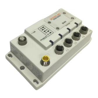
Page 5: Ex500 Part Names
EX500 Part Names Name Communication Connect with EtherNet/IP line. connector Power supply connector Supply power for output devices such as solenoid valve, for input devices such as sensor, and for controlling GW/SI by using power supply connector cable. ( Note1 ) Communication port A ( COM A ) Communication port B... -
Page 6: Specification
Specification Basic specifications Rated voltage 24VDC Range of power Power supply for input and controlling GW/SI : 24VDC supply voltage Power supply for output : 24VDC+10%/-5% ( Voltage drop warning at around 20V ) Rated current Power supply for input and controlling GW/SI : 3.0A Inside GW unit : 0.2A Input device and SI control section : 2.8A Power supply for solenoid valves and output : 3A... -
Page 7: Wiring
Specification ( continued ) Lower-level bus Number of branches for 4 branches ( 16 points/branch ) for input input/output 4 branches ( 16 points/branch ) for output Communication method Protocol : Dedicated for SMC Speed : 750kbps Branch current for input Max. -
Page 8: Communication Wiring
Wiring ( continued ) Communication wiring Connect the cable with Ethernet communication connector to the communication connector of GW unit. Cable connection Aligning the key groove with the communication connector ( 4-pin, socket ) of GW unit, plug the Ethernet communication cable ( plug ). - Page 9 Wiring ( continued ) Separate wiring for power supply for solenoid valves/output and for input and control of GW/SI Both single power supply and two power supply systems can be adopted, however, the wiring shall be made separately ( for solenoid valves/output and for input and controlling GW/SI ) for either system.
- Page 10 Wiring (continued ) For GW unit – Manifold valve – Input unit manifold configuration Two communication connectors in SI unit and one communication connector in Input unit are installed respectively. To the communication connector ( C2 ) or ( 1 ) of SI unit, connect the branch cable with M12 connector from GW.
-
Page 11: Display/Switch Setting
Display/Switch Setting Display GATEWAY UNIT EX500 SERIES LINK COM A COM B COM C Display Content The power supply for solenoids lowering Green lights up The power supply for solenoids normal The power supply off/initialized LINK Green lights up Ethernet communication established Green flashes Data sent/received Communication at 10Mbps... -
Page 12: Si Unit Part Names
Display/Switch Setting (continued ) *1 : Remote control (SW1 all dip-switches off) SMC's EX500 GW Unit will respond to the following Rockwell Automation BOOTP/DHCP Server commands. Enable DHCP Selecting this function will enable the EX500 GW Unit to retrieve its boot information from the BOOTP/DHCP Server. -
Page 13: Mounting/Wiring
Dimensions ( unit : mm ) 1. SI unit for SV series valves ( EX500-S 79.4 68.5 2. SI unit for VQC series valves ( EX500-Q 01 ) 80.3 64.4 ( EX500-Q 02 ) 80.3 64.4 85.7 Mounting/Wiring The mounting and removing methods of SI unit are as shown below. 01 ) 28.6 10 : 2 pcs. -
Page 14: Specification
Specification 1. SI unit for SV series valve ( EX500-S Item Connected block Solenoid valve ( single, double ) Relay output module ( 1-point output, 2- point output ) Connected block Double solenoid valve station Relay output module ( 2-point output ) Single solenoid valve Relay output module ( 1-point output ) Supply voltage for block... -
Page 15: Input Unit Manifold Part Names
Input Unit Manifold Part Names The Input unit manifold consists of Input unit, input block (s), end block and DIN rail. The input block up to 8 can be connected ( 16 points ). Any combination of input blocks ( for M8 connector, M12 connector and 8-point- integrated type ) is acceptable. -
Page 16: Installation
Dimensions ( unit : mm ) (continued ) When only input blocks for M12 connector are connected L2 ( Rail mounting pitch : 12.5 ) Stations L1 [mm] : Rail length 110.5 L2 [mm] : Mounting pitch 112.5 137.5 162.5 L3 [mm] : Manifold length L4 [mm] 12.5... -
Page 17: Wiring
Wiring Branch wiring For wiring method, refer to subsection "Wiring" ( page 15 ) of section "EX500" in this manual. To input devices such as sensor, the power is supplied through the branch wiring ( branch cable with M12 connector ). Therefore, there is no need to supply the power to them individually. -
Page 18: Ex9 Series General Purpose Output Block Part Names
EX9 Series General Purpose Output Block Part Names The EX9 series general purpose output block is the unit to operate solenoid valve, relay, etc. in combination with VQC and SV ( tie-rod ) series valve and applicable SI unit. There are two types ---- one type is for low wattage load ( EX9-OET1 or EX9-OET2 ) that outputs signals by receiving power supply from SI unit, and the other type is for high wattage load ( EX9-OEP1 or EX9-OEP2 ) that outputs signals by receiving power supply from outside. -
Page 19: Mounting
Mounting The mounting and removing methods of each SI unit are as shown below. Supply/exhaust block assembly, end plate R, power block, or other EX9 series general purpose output block 18 : 2 pcs. ( Hexagon socket head cap screw ( with spring washer )) NOTE Holding with hand so that there will be no gap between units and tighten the bolts. - Page 20 Wiring ( continued ) Power supply wiring When combining EX9-OEP1 ( or EX9-OEP2 ) and EX9-PE1 and using external power supply, connect the power supply to the power input connector of EX9-PE1. When selecting power supply, refer to "Handling precautions" ( page 3 ) in this manual. EX9-PE1 power supply connector No.0 M12, 5-pin, reverse key, socket Keep the waterproof cap mounted on power supply connector No.0 while using...
-
Page 21: Specification
Specification 1. EX9-OET1/EX9-OET2/ EX9-OEP1/EX9-OEP2 Item Specification Model No. EX9-OET1 EX9-OET2 No. of output 2 points/unit points Output P-ch MOS-FET N-ch MOS-FET method ( open drain ) ( open drain ) Insulation Optical isolation ( with SI unit ) method Note : To be used in combination with EX9-PE1. For detailed specifications, refer to the instruction manuals, technical data, etc. -
Page 22: Option
Option Cable with Ethernet communication connector For details, refer to subsection "Wiring" ( page 12 ) in section "EX500" in this manual. How to order EX9-AC 020 EN- PSRJ Cable length (L) Connector specification 2 [m] PSRJ M12 plug(straight) Branch cable with M12 connector For details, refer to subsection "Wiring"... -
Page 23: Troubleshooting
Troubleshooting Overall system Item Solution/Corrective action Solenoid valve Check the power for solenoid valves/output ( 24VDC ) doesn't work is supplied. Check the connection of the branch cable with M12 connector to SI unit. Check Power LED and Communication LEDs of SI unit light on.
Need help?
Do you have a question about the EtherNet/IP EX500-GEN1 and is the answer not in the manual?
Questions and answers