Table of Contents
Advertisement
PS-8
PS-8E (100263)
PS-6
PS-6E (100262)
POWER SUPPLIES
273 Branchport Avenue, Long Branch, NJ 07740-6899 Ph: (800) 631-2148 Fax: (732) 222-8707
Web Site: www.coopernotification.com e-mail: info@coopernotification.com
Copyright 2008 Cooper Wheelock Inc., dba Cooper Notification. All rights reserved.
POWERPATH
NAC EXTENDER
Installation Instructions
(105531)
(105530)
P84905-001A
Advertisement
Table of Contents

Related Manuals for POWERPATH PS-8

Summary of Contents for POWERPATH PS-8
- Page 1 POWERPATH PS-8 (105531) PS-8E (100263) PS-6 (105530) PS-6E (100262) NAC EXTENDER POWER SUPPLIES Installation Instructions 273 Branchport Avenue, Long Branch, NJ 07740-6899 Ph: (800) 631-2148 Fax: (732) 222-8707 Web Site: www.coopernotification.com e-mail: info@coopernotification.com Copyright 2008 Cooper Wheelock Inc., dba Cooper Notification. All rights reserved.
-
Page 2: Table Of Contents
4.0 – APPLYING POWER TO THE POWER SUPPLY PANEL 5.0 - TROUBLESHOOTING 6.0 – OPERATION EXAMPLES 7.0 - BATTERY CALCULATION SHEETS 7.1 - PS-8 CALCULATION SHEET 7.2 - PS-6 CALCULATION SHEET 8.0 - LIST OF COMPATIBLE AUXILIARY DEVICES 9.0 - WARRANTY STATEMENT 10.0 APPENDIX A –... -
Page 3: Introduction And Specifications
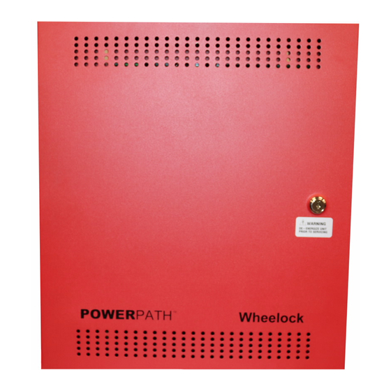
The POWERPATH NAC Extender Power Supply is available in two models: the PS-8 and the PS-6. The PS-8 differs from the PS-6 in the NAC output current and in the enclosure size and the PS-8 enclosure can mount up to two addressable control modules. All other features, indicators and capacities are the same. -
Page 4: Specifications
• 24VDC power limited synchronized outputs. Up to 50 NAC devices per output, maximum line impedance 1.46 Ohms per NAC. • 8 Amp in alarm supply current for the PS-8 (6 Amp in alarm supply current for the PS-6). • Capable of four (4), Class "B" regulated outputs (Maximum of 3 Amps on an output.) •... -
Page 5: Terminology
NC = Normally Closed NO = Normally Open Ahrs = Ampere/Hours Enclosures Figure 1 shows the location of the PC boards and knockouts on the PS-8 panel. 2”, 2 ½”, and 3” Knockouts (2) 1/2” and 3/4" Knockouts (14) Power Supply/Battery... -
Page 6: Installation Instructions
If damage is detected, make an immediate claim to the carrier. Remove the POWERPATH from the shipping container and check that the door lock keys, door lock, and battery connection wires are inside. Make sure the printed circuit boards are within their proper packaging of the enclosure. -
Page 7: Mounting Dimensions
KNOCKOUTS TYP. 17X 0.882+/-.023 & 01.117+/-0.23 FLUSH ON OUTSIDE OF ENCLOSURE ORIENTATION OPTIONAL 10.0" 5.5" 16.7" 14.8" Figure 3: PS-8 Mounting Dimensions DIMENSIONS (H x W x D) – 16.7” x 14.8” x 5.5” P84905-001 A Sheet 7 of 36... -
Page 8: Wiring
DIMENSIONS (H x W x D) – 16.7” x 12.8” x 3” 2.3 WIRING Review the Operation Section (4.0) in order to select the proper hook-up and use of the POWERPATH. Set switches and wire the POWERPATH as follows: Terminal locations for the Power Supply/Battery Charger PC board are shown in Figures 5 and 6. -
Page 9: Figure 5: Ac And Dc Input Wiring Paths
BLACK 120VAC 50-60Hz NON-POWER LIMITED (PS-6, PS-8) GREEN 240VAC 50-60Hz NON-POWER LIMITED (PS-6E, PS-8E) WHITE 10 AMP 250 VAC MICROPROCESSOR TROUBLE BATTERY CHARGER TROUBLE BATTERY TROUBLE AC LOSS TRB BATTERY POWER 10 AMP 250 VAC AC POWER BATTERY D4-D8: SEE... -
Page 10: Figure 6: Power Supply/Battery Charger Pc Board
Input power terminals for 240VAC, 50 to 60 Hz. Non-Power Limited (PS-6E, PS-8E) Backup battery terminals: 24VDC, 7 to 33 Ahrs, Sealed Lead Acid Non-Power Limited. PS-8 – Two 12VDC 12 Ahrs batteries fit inside the enclosure. Batteries larger than 12 Ahrs require an external enclosure such as the Wheelock Product BATC. -
Page 11: Figure 7: Nac Extender Wiring
AC INPUT TERMINALS 10AMP 250VAC BLACK GREEN WHITE AC LOSS TRB 24VDC 1 AMP AC LOSS MAXIMUM RESISTIVE LOAD TROUBLE 10AMP 250VAC (NON SUPERVISED) TERMINALS AC POWER BATTERY D4-D8: SEE TABLE 1 ACTIVE < D8-D4 > D3: GROUND FAULT TROUBLE GROUND FAULT LOCATOR SYNC BUS... -
Page 12: Figure 8: Control Pc Board
PS-8 (PS-6) panel “S BUS IN” terminals. Always place 10K Ohm EOLR on the last panel. Controlled as Master or Remote by switch SW3 Position 4. Up to 40 power supplies can be connected to the PS-8 or 12 to the PS-6. TB2-1,2 SIL+, SIL- Audible Silence: NAC input to the master PS-8 (PS-6) from FACP. - Page 13 G. If all NAC appliances must activate at the same time, connect “OUT4” from the first PS-8 (PS-6) to the “IN1” of the second PS-8 (PS-6). Next connect the “IN1 RET” of the second PS-8 (PS-6) to the next PS-8 (PS-6) “IN1.
-
Page 14: Setting The Dip Switches
3.0 SETTING THE DIP SWITCHES 3.1 CONTROL PC BOARD Refer to Figure 9 for the location and setting of the DIP switches on the Control PC board. 1. Set NAC output DIP Switch(s) on SW1 to follow corresponding input (IN1, IN2). 2. - Page 15 In MASTER Mode SBUS Terminals SYNC/TEMPORAL Terminals Output SYNC Out TEMPORAL In REMOTE Mode Set this switch In REMOTE Mode Set this switch to same setting as MASTER PS-8 to same setting as MASTER PS-8 (PS-6). (PS-6). Position 4 SBUS...
-
Page 16: Applying Power To The Power Supply Panel
BATTERY CALCULATION SHEET is provided on pages 20 and 21. NOTE: The PS-8 enclosure can accommodate two 12VDC batteries up to 12 Ahr in size. Batteries larger than 12 Ahr must be stored in a separate battery enclosure such as the Wheelock BATC Battery Enclosure. -
Page 17: Troubleshooting
• Always de-energize the POWERPATH completely (Remove both AC and DC power) before repairs. • While the POWERPATH is de-energized, perform a visual and hands on check of all terminals and wires to ensure proper termination. • If intermittent troubles occur, use the trouble latch (SW2 Position 4) to find it. -
Page 18: Figure 12: Power Supply/Battery Charger Pc Board Trouble Led Locations
Troubleshooting Using the LED Indicators Power Supply/Battery Charger PC Board. AC LOSS TRB MICROPROCESSOR TROUBLE BATTERY POWER BATTERY CHARGER TROUBLE BATTERY TROUBLE AC POWER BATTERY Figure 12: Power Supply/Battery Charger PC Board Trouble LED Locations Table 6: Power Supply/Battery Charger PC Board LED Trouble Indicators Identification Description Action... -
Page 19: Figure 13: Control Pc Board Trouble Led Locations
Control PC Board Coded Trouble LEDs D8, D7, D6, D5, D4 D4-D8: SEE TABLE 9 TROUBLE LATCH OFF/ON ACTIVE SBUS IN1/IN2 IN2 FOLLOWER OFF/ON IN1 FOLLOWER OFF/ON < D8-D4 > D3: GROUND FAULT TROUBLE NAC4 SYNC/TEMPORAL NAC3 SYNC/TEMPORAL NAC2 SYNC/TEMPORAL NAC1 SYNC/TEMPORAL GROUND FAULT LOCATOR... -
Page 20: Table 8: Control Pc Board Trouble Priority Identification
Trouble Condition Priority Identification When multiple troubles exist the Control PC board Coded Trouble LED Indicators indicate the highest priority trouble. Table 8 shows the priority sequence. When the highest priority is repaired, the next highest priority will automatically be displayed. - Page 21 AUX Output Current Limit Reduce the number of NAC Appliances on Output1 □ ■ ■ □ ■ □ SYNC BUS Short Check for a wiring short. Check for improperly wired NAC □ ■ ■ ■ □ □ circuit. (If an appliance is wired + to – and – to + a short trouble will be indicated.
-
Page 22: Operation Examples
• This mode will only synchronize Wheelock horns, horn strobes, and strobes with the synchronization capability. • If only strobes are connected to the POWERPATH outputs, the SILENCE input is not required. Example 2: TEMPORAL MODE (CLASS B) D4-D8: SEE... - Page 23 Example 3: IN>OUT SYNC MODE from CODED INPUT SOURCE (CLASS B) D4-D8: SEE TABLE 9 TROUBLE LATCH OFF/ON ACTIVE SBUS IN1/IN2 IN2 FOLLOWER OFF/ON < D8-D4 > IN1 FOLLOWER OFF/ON D3: GROUND FAULT TROUBLE NAC4 SYNC/TEMPORAL NAC3 SYNC/TEMPORAL GROUND FAULT NAC2 SYNC/TEMPORAL LOCATOR NAC1 SYNC/TEMPORAL...
- Page 24 Example 5: WHEELOCK SYNC MODE without Audible Silence (CLASS A) D4-D8: SEE TABLE 9 TROUBLE LATCH OFF/ON ACTIVE SBUS IN1/IN2 IN2 FOLLOWER OFF/ON < D8-D4 > IN1 FOLLOWER OFF/ON D3: GROUND FAULT TROUBLE NAC4 SYNC/TEMPORAL NAC3 SYNC/TEMPORAL GROUND FAULT NAC2 SYNC/TEMPORAL LOCATOR NAC1 SYNC/TEMPORAL NAC4 IN1/IN2...
- Page 25 Example 7: IN>OUT SYNC MODE from CODED INPUT SOURCE (CLASS A) D4-D8: SEE TABLE 9 TROUBLE LATCH OFF/ON ACTIVE SBUS IN1/IN2 IN2 FOLLOWER OFF/ON < D8-D4 > IN1 FOLLOWER OFF/ON D3: GROUND FAULT TROUBLE NAC4 SYNC/TEMPORAL NAC3 SYNC/TEMPORAL GROUND FAULT NAC2 SYNC/TEMPORAL LOCATOR NAC1 SYNC/TEMPORAL...
- Page 26 ADDRESSABLE TO FACP TO NEXT APPLIANCE CONTROL SLC LOOP OR EOLR (10K OHMS) MODULE PS-8 ENCLOSURE SLC LOOP • This mode will only synchronize Wheelock horns, horn strobes, and strobes with the synchronization capability. P84905-001 A Sheet 26 of 36...
- Page 27 Example 11: NAC STROBES ACTIVATED SEPERATELY, with all circuits synchronized PS-8 ENCLOSURE D4-D8: SEE TABLE 9 TROUBLE LATCH OFF/ON ACTIVE SBUS IN1/IN2 IN2 FOLLOWER OFF/ON < D8-D4 > IN1 FOLLOWER OFF/ON D3: GROUND FAULT TROUBLE NAC4 SYNC/TEMPORAL NAC3 SYNC/TEMPORAL GROUND FAULT...
- Page 28 Example 12: NAC HORNS ACTIVATED SEPARATELY, with all circuits synchronized D4-D8: SEE TABLE 9 TROUBLE LATCH OFF/ON ACTIVE SBUS IN1/IN2 IN2 FOLLOWER OFF/ON < D8-D4 > IN1 FOLLOWER OFF/ON D3: GROUND FAULT TROUBLE NAC4 SYNC/TEMPORAL NAC3 SYNC/TEMPORAL GROUND FAULT NAC2 SYNC/TEMPORAL LOCATOR NAC1 SYNC/TEMPORAL NAC4 IN1/IN2...
- Page 29 Example 13: NAC APPLIANCES SYNCHRONIZED all at the same time D4-D8: SEE TABLE 9 TROUBLE LATCH OFF/ON ACTIVE SBUS IN1/IN2 IN2 FOLLOWER OFF/ON < D8-D4 > IN1 FOLLOWER OFF/ON D3: GROUND FAULT TROUBLE NAC4 SYNC/TEMPORAL NAC3 SYNC/TEMPORAL GROUND FAULT NAC2 SYNC/TEMPORAL LOCATOR NAC1 SYNC/TEMPORAL NAC4 IN1/IN2...
- Page 30 Example 14: NON-RESETTABLE POWER APPLICATION D4-D8: SEE TABLE 9 TROUBLE LATCH OFF/ON ACTIVE SBUS IN1/IN2 IN2 FOLLOWER OFF/ON < D8-D4 > IN1 FOLLOWER OFF/ON D3: GROUND FAULT TROUBLE NAC4 SYNC/TEMPORAL NAC3 SYNC/TEMPORAL GROUND FAULT NAC2 SYNC/TEMPORAL LOCATOR NAC1 SYNC/TEMPORAL NAC4 IN1/IN2 SYNC BUS INPUT1 NAC3 IN1/IN2...
-
Page 31: Battery Calculation Sheets
BATTERY CALCULATION SHEET PS-8 BATTERY CALCULATION SHEET STANDBY CURRENT CALCULATIONS: 1. The Standby Current for the PS-8 is 0.129 Amps. 0.129 Amps 2. If this unit is set for Master Mode, multiply the number of remote units by 0.006 Amps. -
Page 32: Ps-6 Calculation Sheet
PS-6 BATTERY CALCULATION SHEET STANDBY CURRENT CALCULATIONS: 1. The Standby Current for the PS-6 is 0.129 Amps. 0.129 Amps 2. If this unit is set for Master Mode, multiply the number of remote units by 0.006 Amps. Amps If this unit is set for Remote Mode, enter 0 Amps. 3. -
Page 33: List Of Compatible Auxiliary Devices
8.0 LIST OF COMPATIBLE AUXILIARY DEVICES LIST OF COMPATIBLE AUXILIARY DEVICES For use with AUX CP MODE ONLY Manufacturer Model GE/EST SD-4WJ/ESD-4WJ D285DH BOSCH D282A/D283A MMF-300 FIRELITE CMF-300 CRF-300 SL-2000 SPACE AGE SM-501 GENTEX 8000/8003 4WTAB 4WTARB 4WITARB SYSTEM 4WTRB SENSOR 4WTB DH100ACDCLP... -
Page 34: Warranty Statement
9.0 WARRANTY STATEMENT: Limited Warranty Cooper Wheelock Inc., dba Cooper Notification products must be used within their published specifications and must be PROPERLY specified, applied, installed, operated, maintained, and operationally tested in accordance with these instructions at the time of installation and at least twice a year or more often in accordance with local, state and federal codes, regulations and laws. -
Page 35: Appendix A - List Of Compatible Nac Devices
10.0 LIST OF COMPATIBLE NAC DEVICES: APPENDIX A The following is a list of appliances produced by Cooper Wheelock that are compatible with the Wheelock power supplies. SYNCHRONIZING HORNS AH-12 AH-24 AH-12WP AH-24WP HS-24 MIZ-24S NH-12/24 ----------- ----------- SYNCHRONIZING HORN STROBES AS-121575W AS-241575W AS-24MCW... - Page 36 APPLIANCES WITH SYNCHRONIZING STROBES AMT-241575W AMT4-241575W AMT-2475W AMT4-2475W AMT-241575W-NYC AMT4-241575W-NYC AMT-2475W-NYC AMT4-2475W-NYC MT-12575W ---------- MT-241575W MT-2475W MTWP-2475W ET70WP-2475W CH70-24MCW CH90-24MCW CH70-24MCC CH90-24MCC CH70-2415C CH90-2415C CH70-2430C CH90-2430C CH70-2475C CH90-2475C CH70-24100C CH90-24100C CH70-24150C CH90-24150C CH70-24177C CH90-24177C CH70-24150W CH90-24150W CH70-24MCWH CH90-24MCCH CH70-24185W CH90-24185W E70-24MCW E90-24MCW E70-24MCC...
Need help?
Do you have a question about the PS-8 and is the answer not in the manual?
Questions and answers