
Related Manuals for MSA SM5000


Summary of Contents for MSA SM5000
- Page 1 Instruction Manual SM5000 Sampling Module, DC Pump Model Order No.: 10103804/02 Print spec.: 10000005389(A) MSAsafety.com...
- Page 2 The warranties made by MSA with respect to the product are voided if the product is not used and serviced in accordance with the instructions in this manual. Please protect yourself and others by following them.
- Page 3 This exclusion is applicable to claims for breach of warranty, tortious conduct or any other cause of action against seller. SM5000 Sampling Module - DC Pump Model...
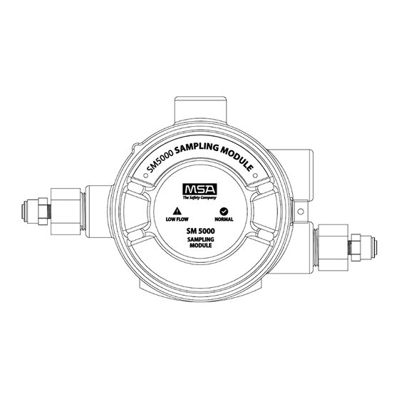
- Page 4 2. An SM5000 Sampling Module - DC Pump Model is designed to sample gases or vapors in air. It cannot sample the concentration of gases or vapors in steam or condensing streams or inert or oxygen defi- cient atmospheres.
-
Page 5: Table Of Contents
1.1.1 The SM5000 Sampling Module - DC Pump Model: ....... . -
Page 6: General Information
General Information General Information Introduction 1.1.1 The SM5000 Sampling Module - DC Pump Model: • must be used with an Ultima X, Ultima X5000, or an S5000 Gas Monitor with a digital sensor (available separately). NOTE: Does not work with S5000 IR400, passive catalytic bead or metal oxide semiconductor (MOS) sensors. - Page 7 General Information Fig. 1 Sampling module installation with Ultima X5000 oxygen, toxic, and catalytic combustible sensors SM5000 Sampling Module - DC Pump Model...
-
Page 8: Unpacking Unit
There is one possible Pump Sampling Module configuration: • Explosion-proof (P/N 10043264) unit Reference the identification label located on the side of the unit (see Fig. 3). See Tab. 1 for unit specifica- tions. SM5000 Sampling Module - DC Pump Model... - Page 9 Flow failure relay at 2.0 Amps, 30 Volts DC Temperature range -20°C to 55°C (-4 to 122°F) Humidity 15 to 95% RH, non-condensing Tab. 1 Performance specifications for SM5000 Sampling Module - DC Pump Model SM5000 Sampling Module - DC Pump Model...
-
Page 10: Terminology
A zero (0) indication on the meter display usually indicates ambient air Zero present or no hazardous gases present. Zeroing Processes for placing a zero indication on meter display. Tab. 2 Terminology SM5000 Sampling Module - DC Pump Model... -
Page 11: Installation
By using the optional mounting bracket (P/N 10179361) for the Ultima X5000 Gas Monitor. • Assemblies are also available that will allow monitoring in vent pipe lines 4-6" in diameter. Use PN 10147544 for digital sensors and PN 10126895 for XIR/XIR PLUS sensors. SM5000 Sampling Module - DC Pump Model... -
Page 12: Sample Line Placement Between Pump Sampling Module And Ultima X, Ultima X5000, Or S5000 Gas Monitor
The in-line filter must be used before the Pump Sampling Module to prevent water entry from damaging unit. If installing additional gas monitors, install tubing between units as shown in Fig. 4. Use tubing compatible with the gas being sampled. MSA tubing is available (P/N 600771). SM5000 Sampling Module - DC Pump Model... - Page 13 Installation Fig. 4 Three Ultima X5000 Gas Monitors and a Sampling Module SM5000 Sampling Module - DC Pump Model...
-
Page 14: Sample Line Placement
With the above gases, use filter (P/N 637921). The filter and sample line should be inspected periodically and replaced if dirty. CAUTION! Do not attempt to clean the sample line by applying compressed air. All gas monitors must be mounted in ambient, interference-free air; otherwise, erroneous readings may result. SM5000 Sampling Module - DC Pump Model... -
Page 15: Exhaust Line Placement
Fasten the end of the exhaust tubing in the area of interest by using suitable hardware (not supplied). NOTE: Exhaust inlet should be pointed downward to prevent dirt and water from entering the exhaust tubing line. Check for leaks along entire length of the exhaust tubing line. SM5000 Sampling Module - DC Pump Model... -
Page 16: Electrical Connection
NOTE: The Pump Sampling Module utilizes a shielded four-conductor wiring harness. It is recommended to use the shielded wire harness if installing the system where portable two-way radio, welding or large machinery are located. Fig. 5 Typical wiring - Ultima X SM5000 Sampling Module - DC Pump Model... - Page 17 Installation Fig. 6 Typical wiring - SM5000 and X5000 SM5000 Sampling Module - DC Pump Model...
-
Page 18: Electrical Connection Procedure
If not using the attached wire harness: • Remove and discard the wiring harness. • Install a conduit seal into the enclosure. • Use of Teflon tape or non-hardening thread sealant for environmental reasons is acceptable. SM5000 Sampling Module - DC Pump Model... -
Page 19: Initial Start-Up
Pump Sampling Module and gas monitor adjustments are completed. Ensure the exhaust is not restricted. The front panel low flow indication, red LED, should NOT be ON. NOTE: If front panel low flow indication is ON, see chapter 4.3 "Troubleshooting Guidelines". SM5000 Sampling Module - DC Pump Model... -
Page 20: Calibration And Operation
If this calibration procedure cannot be performed at any step, consult chapter 4.3 "Troubleshooting Guide- lines", localize the problem and replace the inoperative component. MSA offers periodic service that is available on a contract basis; for more information, please call MSA at 1-800-MSA-INST. -
Page 21: Spanning With The Pump Sampling Module
See chapter 4.3 "Troubleshooting Guidelines" for corrective action. WARNING! The pressure switch can fail and the orifice can clog if water enters the system. Always use the proper in- line filter (P/N 10051406). SM5000 Sampling Module - DC Pump Model... -
Page 22: Maintenance And Troubleshooting Guidelines
No power to the unit Turn control instrument ON Improper voltage selection at the Select proper voltage at the control control instrument instrument Inoperative relay Replace printed circuit board assembly Tab. 5 Troubleshooting guidelines SM5000 Sampling Module - DC Pump Model... -
Page 23: Replacement Parts
4-6" vent pipe mount - XIR/XIR PLUS sensor 10126895 Water deflector 10087383 Tab. 6 Parts list NOTE: It is the user’s responsibility to follow all applicable regulations and to ensure continued compliance with the certification, as marked on the label. SM5000 Sampling Module - DC Pump Model... - Page 24 For local MSA contacts, please visit us at MSAsafety.com Because every life has a purpose...
Need help?
Do you have a question about the SM5000 and is the answer not in the manual?
Questions and answers