
Summary of Contents for allen XL5000 STANDARD
- Page 1 XL5000 THERMOTRANSFER-PRINTING SYSTEMS XL5000 (Standard) XL5000 (Opposite) OPERATING INSTRUCTIONS...
-
Page 3: Important Notes
The information provided in these operating instructions relate to the devices described under “Applicability”. Copyright The present document and the described devices therein belong to the company Allen Coding GmbH. All rights remain reserved. Reproduction of this document, in full or in part, requires prior explicit and written approval of the company Allen Coding GmbH. - Page 4 Disclaimer The company Allen Coding GmbH undertakes all measures to ensure that the published document is up to date at the time of publication. However, no guarantee may be given that the document is error-free. The Allen Coding GmbH does not accept liability for possible damages that may have been caused by faulty information in this document.
-
Page 5: Table Of Contents
TABLE OF CONTENTS Table of Contents Important Notes .......................... 3 Table of Contents ........................5 Product identification ......................8 Characteristic data ..............................8 Compliant use ................................9 1.2.1 Ambient conditions ..............................9 1.2.2 Designated use ................................9 1.2.3 Qualification of personnel ............................10 Technical data ................................ - Page 6 TABLE OF CONTENTS Communication via the serial interface (RS-232)..................... 33 Communication via the Ethernet connection ......................33 Continuous operation (CM) ............................. 34 4.5.1 Modifications to the printing system ........................34 4.5.2 Installing the encoder .............................. 35 Installation of a warning light ..........................36 Performing a test print .............................
- Page 7 TABLE OF CONTENTS Pneumatic diagram ................................66 Recommended spare and wear parts ..........................67 Available spare part kits ..............................68 Exploded view ..................................78 XL5000 M02001102EN0319...
-
Page 8: Product Identification
PRODUCT IDENTIFICATION Product identification 1.1 Characteristic data General XL5000 Part number Standard - Europe 103810-1 Opposite - Europe 103810-2 Standard - US 103810-3 Opposite - US 103810-4 Standard - China 103810-5 Opposite - China 103810-6 Operating mode Intermittent (IM) Continuous (CM) Material stainless steel, anodized aluminum, plastic Print resolution... -
Page 9: Compliant Use
PRODUCT IDENTIFICATION 1.2 Compliant use 1.2.1 Ambient conditions XL5000 (Standard / Opposite): Ambient temperature, operation [°C] ([°F]) +5 to +40 (+40 to +104) Relative humidity, operation (non-condensing) 20 to 75 Protection class [IP] IP20 Ambient temperature, transport and storage [°C] ([°F]) -25 to +55 (-13 to +131) Relative humidity, transport and storage 20 to 75... -
Page 10: Qualification Of Personnel
PRODUCT IDENTIFICATION 1.2.3 Qualification of personnel Operation and set-up: Operation and set-up of the device may only be performed by sufficiently qualified and trained personnel that have been authorized by operator to perform these tasks. Installation, cleaning and maintenance: Installation, cleaning and maintenance of the device may only be performed by fully qualified and trained technical per- sonnel. -
Page 11: Electrical Data
PRODUCT IDENTIFICATION Pneumatic service unit dimensions (A) Width [mm] (B) Height [mm] (C) Depth [mm] (D) Distance assembly holes [mm] [mm] [mm] 17.5 Pneumatic service unit weight Pneumatic service unit [kg] 1.3.2 Electrical data Power supply input: Voltage 100 - 240 Frequency [Hz] 50 - 60... -
Page 12: Pneumatic Data
PRODUCT IDENTIFICATION 1.3.3 Pneumatic data The unit requires a normal industry supply of oil-free, clean and dry air. The air supply requirement is: Printing system: Air supply (input) [MPa] ([bar] or [psi]) (5 or 75) Connection for air supply tubing with outside [mm] diameter Requirements for compressed air supply... -
Page 13: Identification Of The Device
PRODUCT IDENTIFICATION 1.4 Identification of the device Type plate The type plate attached to the device contains the following data: ① Equipment type ⑥ Production build ② Part number ⑦ CE mark Electrical data: voltage, maximum input current, ③ Serial number ⑧... -
Page 14: Emc Compliance Statements
PRODUCT IDENTIFICATION 1.5.2 EMC Compliance Statements European Union (EU) Electromagnetic Compatibility Directive Compliance Statement This product is in conformity with the protection requirements of EU Council Directive 2014/30/EU on the approxima- tion of the laws of the Member States relating to electromagnetic compatibility. Federal Communications Commission (FCC) Emissions Compliance Statement This equipment has been tested and complies with the limits for a Class A digital device, pursuant to Part 15 of the FCC Rules. -
Page 15: Product Specifications
Deficiencies and/or incompleteness immediately to the manufacturer or your distributor. The following components belong to the standard deliverable items for the device: Position Part number Description 103810-1 XL5000 Standard – EU 103810-2 XL5000 Opposite – EU 103810-3 XL5000 Standard – US 103810-4 XL5000 Opposite –... - Page 16 PRODUCT SPECIFICATIONS Optional equipment: 103808 Kit CM print 103309 Preheater 6000-828 LED alarm beacon Overview standard deliverable items: ① Printing system ③ Sample ribbon ② Power supply with connection cable ④ Kit accessories XL5000 M02001102EN0319...
-
Page 17: Description Of Device
PRODUCT SPECIFICATIONS 2.3 Description of device WARNING Personal injury! ▪ Read and follow safety rules and guidelines in chapter 3 before attempting to setup or operate this equipment The new XL5000 printers incorporate state-of-the-art technology. They are designed to print bar codes, alphanumeric texts, dates, times, logos, and other images directly onto the surface of packaging materials such as plastics, laminates, cellophane, cardboard, self-adhesives, etc. -
Page 18: Layout Of The Printing System
PRODUCT SPECIFICATIONS 2.3.1 Layout of the printing system Printer base unit ① ② ③ ④ ① Cassette sensor ③ Home sensor ② Ribbon sensor ④ Thermal printhead XL5000 M02001102EN0319... - Page 19 PRODUCT SPECIFICATIONS Ribbon cassette ③ ① ④ ② ① Ribbon unwind ③ Tensioner ribbon unwind Ribbon upwind Tensioner ribbon upwind ② ④ XL5000 M02001102EN0319...
-
Page 20: Pneumatic Service Unit
PRODUCT SPECIFICATIONS 2.3.2 Pneumatic service unit Air supply connection (Ø 6 mm, to connect to the ① Air pressure supply connection (Ø 6 mm) ② printing system) XL5000 M02001102EN0319... -
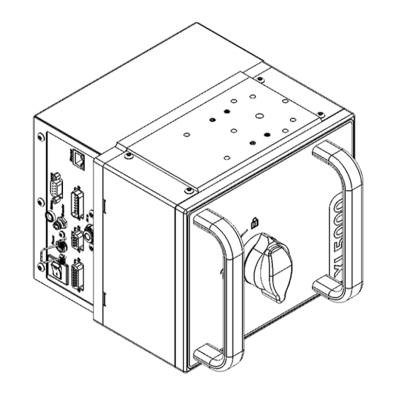
Page 21: Interface Of The Printing System
PRODUCT SPECIFICATIONS 2.3.3 Interface of the printing system ③ ① ② ⑤ ④ ⑨ ⑧ ⑦ ⑥ ⑩ ① 24 V power ON/OFF switch ⑥ Ethernet port ② 24 V input ⑦ Printer input signal from host machine ③ Printer status LED ⑧... - Page 22 PRODUCT SPECIFICATIONS 5. Alarm beacon (D-sub 9-pin Socket) Description/Function Error Warning ON (+24 V 6. Ethernet connection (RJ-45 Socket) Description/Function 7. I/O interface (D-sub 15-pin plug) Description/Function Free/Busy (output) On cycle / printed (output) Common pins 1-2 Error N.C. Error common pin Error N.O.
- Page 23 PRODUCT SPECIFICATIONS 8. Serial communication interface (RS-232, D-sub 9-pin Socket) Description/Function 9. Control terminal interface a:touch Lite (D-Sub 15-pin Socket) Description/Function VCC + 5 V VCC + 5 V VCC + 5 V VCC + 5 V VCC + 5 V XL5000 M02001102EN0319...
-
Page 24: Connection Possibilities And Connection Of Components
PRODUCT SPECIFICATIONS 2.3.4 Connection possibilities and connection of components WARNING Personal injury! ▪ Read and follow safety rules and guidelines in chapter 3 before attempting to setup or operate this equipment ⑥ ⑦ ② ① ④ ⑤ ③ ① Host machine (see “Electrical installation” for ⑤... - Page 25 PRODUCT SPECIFICATIONS Power supply Position the 24 V power supply close to the printing system and connect the output cable to the 24 V connector of the printing system. Secure connector by engaging spring or clamp. Air supply 1. Position and secure the pressure regulator close to the printing system or in an accessible place where it is easy to operate.
-
Page 26: Safety Information
SAFETY INFORMATION Safety Information This Chapter contains information on the configuration and relevance of the safety information presented in these op- erating instructions, and information on possible hazards which may occur even for compliant usage of the device. 3.1 Configuration of the safety instructions SIGNAL WORD Type and source of hazard Explanation of the hazard and information on possible consequences of non-compliance... -
Page 27: Used Pictograms
SAFETY INFORMATION 3.2 Used pictograms Pictogram Meaning Warning of a general hazard Warning of possible property damages Before performance, observe the corresponding information in the operating manual General note 3.3 Hazards during compliant use CAUTION Hot machine parts! A thermal printhead can have hot surface temperatures during operation. Contacts with the surface can cause burns. -
Page 28: Installation
INSTALLATION Installation In the following chapter, you will find information on installation of the device. CAUTION Potential hazard due to incorrect or non-compliant installation! An incorrect or improper assembly of the device may impair safety, functionality and efficiency of the de- vice. -
Page 29: Installing The Printing System
INSTALLATION Installing the printing system CAUTION Safety deficits by incorrect or improper assembly of the printing system An incorrect or improper assembly of the printing system may impair safety, functionality and efficiency of the printing system. Any liability and warranty for any damages caused by incorrect or improper as- sembly of the printing system is excluded by the manufacturer. - Page 30 INSTALLATION ▪ Setup of the printhead - adjusting the distance to the material to be printed Machine support basic setting: Recommended distance of the lower edge of the printing system to the upper edge [mm] 2 - 3 of the product to be printed ▪...
-
Page 31: Electrical Installation
INSTALLATION 4.2.2 Electrical installation ATTENTION Fastening the cables The printing system can be damaged if a cable comes loose or is pulled out when the printing system is switched on. The manufacturer assumes no warranty and liability for the resulting damage. ▪... - Page 32 INSTALLATION NOTE Power rating of relay signal output “Error” The following limits for the relay-signal output must not be exceeded: = 250 V max. = 8 A max. NOTE Input signal The following limits for the input signal must not be exceeded: = 24 V max.
-
Page 33: Establishing The Compressed Air Connection
INSTALLATION 4.2.3 Establishing the compressed air connection NOTE Compressed air supply Switch on the compressed air supply with the recommended value (see "Connection possibilities and connection of components") before you switch on the printing system. Step 1: Establishing the compressed air supply connection Connect the compressed air supply connection on the pneumatic service unit to the compressed air supply. -
Page 34: Continuous Operation (Cm)
INSTALLATION Continuous operation (CM) The XL5000 can be changed from intermittent to continuous operating mode easily. Minor modifications to the printing system as well as the installation of an encoder are necessary, only. The following two chapters provide a detailed de- scription. -
Page 35: Installing The Encoder
INSTALLATION 4.5.2 Installing the encoder Encoder Specification: Resolution [pulses / rotation] 2000 Encoder wheel diameter [mm] Step 1: Assemble the encoder Assemble the encoder to the machine frame so that the printed material runs between rubber transport roller and wheel of the encoder. Make sure that the wheel of the encoder is pressed tightly against the printed material. -
Page 36: Installation Of A Warning Light
INSTALLATION Installation of a warning light ATTENTION Maximum current consumption warning light The current consumption of a connected warning light must not exceed 1 A. Greater current consumption can destroy parts of the system. ▪ Make sure that the current consumption of a connected warning light may not exceed 1 A. For installation of the (optional) warning light, connect it with the provided interface of the printing system. -
Page 37: Conversion From Outside Coated To Inside Coated Ribbon
INSTALLATION 4.8 Conversion from outside coated to inside coated ribbon Rotation clockwise: XL5000 – Standard: außenbeschichtet XL5000 – Opposite: innenbeschichtet Rotation counterclockwise: XL5000 – Standard: innenbeschichtet XL5000 – Opposite: außenbeschichtet XL5000 M02001102EN0319... -
Page 38: Operating
Operating Switching the printing system on/off Use the power supply switch to switch the printing system on or off. Overview of operating and configuration possibilities The easiest way for operation and configuration of the printing system is to use the a:control software. The software can be installed on a computer or laptop. - Page 39 OPERATING ATTENTION Use of ribbon that is not specified by the manufacturer The use of ribbons that were not specified by the manufacturer can lead to excessive wear or damage to the thermal printhead. ▪ Only use ribbons with the width specified by the manufacturer. For information about this, refer to the "Characteristic data".
- Page 40 OPERATING Step 3: Inserting a new cardboard sleeve Remove the cardboard sleeve from the ribbon unwind. Slide an empty cardboard sleeve onto the ribbon upwind. You may use the cardboard sleeve that was previously removed from the ribbon unwind for this. Step 4: Check rubber drive roller and clean it if required Check the condition of the rubber drive roller.
-
Page 41: Transmitting Print Images
OPERATING 5.4 Transmitting print images NOTE Print image creation Print image creation takes place with the label design software, for example with a:design 2. A created print image can be transmitted to the printing system using the configuration or design software. Firmware update A firmware update of the printing system is possible via the a:control software or using the specially developed control panel. -
Page 42: Error Detection And Management
ERROR DETECTION AND MANAGEMENT Error detection and management Printer errors are usually identified by the error messages displayed on the control terminal. You can use the test label to check the print quality. NOTE Error messages Please refer to the control terminal User´s Guide for a comprehensive description of all error messages. 6.1 Print quality CORRECT PRINTOUT PRINTOUT WITH BLURRY VERTICAL BANDS... -
Page 43: Other Faults
ERROR DETECTION AND MANAGEMENT Other faults Description Cause Remedy ▪ Incorrect ribbon type used. Check whether the correct rib- bon and not e.g. hot stamping ribbon, etc. is used. ▪ Ribbon was loaded incorrectly. The Ensure that the correct side of incorrect side of the ribbon is in con- the ribbon (shiny) comes into tact with the thermal printhead. - Page 44 ERROR DETECTION AND MANAGEMENT Description Cause Remedy ▪ The thermal printhead is dirty. Clean the thermal printhead ac- cording to the instructions in the operating manual. Missing pixels in the print. ▪ The thermal printhead is worn out. If necessary, replace the thermal printhead.
-
Page 45: Cleaning And Maintenance
CLEANING AND MAINTENANCE Cleaning and maintenance CAUTION Hazards during cleaning and maintenance activities! Switch off the device during cleaning and maintenance work. Otherwise, personnel safety may be at risk and damage to the device or other nearby property may result. ▪... -
Page 46: Cleaning
CLEANING AND MAINTENANCE 7.1 Cleaning CAUTION Hazards when working with technical cleaning towels Incorrect handling of technical cleaning towels can entail a hazard for persons and/or property. ▪ Please observe the warning notices on the packaging of the technical cleaning towels. ATTENTION Damage to the equipment due to incorrect cleaning The use of incorrect cleaning methods and the use of incorrect cleaning materials can damage the elec-... - Page 47 CLEANING AND MAINTENANCE Overview of cleaning tasks Cleaning interval Recommended cleaning Task agent With each replacement of the Technical cleaning towels Cleaning of the thermal printhead. ribbon, or before and after an Art no.: 1.0000.45008 Clean the thermal printhead until no wax / resin 8-hour shift at the latest.
-
Page 48: Maintenance
CLEANING AND MAINTENANCE 7.2 Maintenance NOTE Printing substrate The printing substrate is subject to operationally related wear. Therefore, we recommend storing ap- propriate spare parts. 7.2.1 Overview of maintenance tasks NOTE Performing service on the printing system The manufacturer recommends service on the printing system after 20000000 prints and/or after one year. -
Page 49: Replacing A Thermal Printhead
Thermal printheads are electrostatically sensitive electronic components. Incorrect handling can damage or destroy the thermal printhead due to ESD voltage flashovers. Any liability and warranty for any dam- ages caused by incorrect handling of the printing system is excluded by Allen Coding GmbH. ▪... - Page 50 CLEANING AND MAINTENANCE Removing the thermal printhead Step 1: Disconnecting the power supply Switch the printing system off at the power supply switch and disconnect it from the power supply. Step 2: Removing the cassette Unlock the cassette by turning the cassette latch counterclockwise. Move the cassette out of the printer. Step 3: Removing the cable Remove the cables from the thermal printhead.
- Page 51 CLEANING AND MAINTENANCE Installing the thermal printhead Step 1: Making note of the resistance value Make note of the resistance value of the thermal printhead before installing it. The specification is provided on the white stocker on the thermal printhead. Step 2: Installing thermal printhead Fit the thermal printhead to the bracket and fasten it with the provided fastening screws.
-
Page 52: Inspection And Replacement Of The Toothed Belt
Connect the printing system to the power supply and switch on the printing system at the power supply switch. 7.2.4 Adjusting the ribbon tension NOTE Tools required to adjust tension: ▪ 2.5 mm Allen wrench ▪ Roll of ribbon or ribbon cardboard core – 42 mm diameter max. ▪ Spring scale with test band XL5000... - Page 53 CLEANING AND MAINTENANCE Ribbon unwind NOTE Replace Drag Cord. After replacing the drag cord, ribbon tension needs to be readjusted after 10 hours of operation. ATTENTION Friction disc and tensioner ribbon unwind Do not lubricate or wet tensioner ribbon unwind and friction disc Standard: ④...
- Page 54 CLEANING AND MAINTENANCE ① ③ Tensioner ribbon unwind Ribbon unwind ② ④ Friction Disc Tension spring You can use a spring scale and a roll of ribbon (outer diameter 42 mm) or ribbon cardboard core for adjustment of the ribbon tension. Perform the following steps: Step 1: Preparation of measurement setup Wrap the test band (test cord) on the ribbon cardboard core.
- Page 55 CLEANING AND MAINTENANCE Ribbon upwind Standard: Opposite: ① ③ Tensioner ribbon upwind Rubber drive roller ② ④ Ribbon upwind spindle Polycord® belt XL5000 M02001102EN0319...
- Page 56 CLEANING AND MAINTENANCE NOTE Ribbon-upwind The default setting for the tensioner is centered. If the upwind is too tight or too loose, adjust with the tensioner. XL5000 M02001102EN0319...
-
Page 57: Internal Wiring
CLEANING AND MAINTENANCE 7.2.5 Internal wiring If it is necessary to replace components in the scope of maintenance or repairs that carry electric current, please refer to the following schematic diagrams for the internal wiring. Power supply ① Power supply – input main switch ②... - Page 58 CLEANING AND MAINTENANCE Motors ① Stepper motor - ribbon ② Stepper motor - carriage Printhead ① Internal connection cable ② Connection cable printhead XL5000 M02001102EN0319...
- Page 59 CLEANING AND MAINTENANCE Sensors, encoder, alarm beacon and pneumatic control ① ⑤ Status LED Home sensor ② ⑥ Encoder Cassette sensor ③ ⑦ Alarm beacon Valve - pre stroke ④ ⑧ Ribbon sensor Valve - print stroke XL5000 M02001102EN0319...
-
Page 60: Pneumatic Connection
CLEANING AND MAINTENANCE 7.2.6 Pneumatic connection If it is necessary to replace components in the scope of maintenance or repairs that have a pneumatic connection, please refer to the following schematic diagrams. The specified diameters refer to the outside diameter of the hoses. Pneumatic connection: air in –... -
Page 61: Repairs
Repairs 8.1 Spare parts Refer to the spare parts list under “Overview“ in the appendix. 8.2 Service address Europe: Germany Allen Coding GmbH ITW Ltd. Service Department Unit 9, Gateway 1000, Whittle Way, Friedrich-Bergius-Ring 30 Arlington Business Park, Stevenage, D-97076 Würzburg Hertfordshire SG1 2FP Tel.:... -
Page 62: Transport And Storage
TRANSPORT AND STORAGE Transport and storage 9.1 Transport WARNUNG Hazard due to improper securing of load Improper securing of the device during transport can result in unpredictable hazards to persons and/or property damage. ▪ Secure the device in accordance with instructions. ▪... -
Page 63: Disposal
DISPOSAL 10 Disposal The device consists of various materials which can be recycled and which must be disposed of separately. In the event of disposal of the device, follow the relevant legal guidelines. Since the disposal guidelines may differ from country to country, please consult with your supplier as necessary. -
Page 64: Appendix
APPENDIX Appendix EC-compliance statement XL5000 M02001102EN0319... -
Page 65: Open Source License Notice
APPENDIX Open source license notice This product includes software developed by the Zint Barcode Generator Project (https://sourceforge.net/projects/zint) Zint backend license libzint - the open source barcode library Copyright (C) 2009 Robin Stuart <robin@zint.org.uk> Redistribution and use in source and binary forms, with or without modification, are permitted provided that the following conditions are met: 1. -
Page 66: Pneumatic Diagram
APPENDIX Pneumatic diagram ① ② ③ ① ③ Air supply tubing 6 mm outside diameter Printer connector panel Printer air supply tubing – 6 mm outside diame- ② XL5000 M02001102EN0319... -
Page 67: Recommended Spare And Wear Parts
APPENDIX Recommended spare and wear parts Recommendation of the manufacturer For customers performing simple maintenance work For customers performing simple service work by themselves For customers performing entirely service work by themselves Printing system Recommen- Part No. Description dation 101935-1 Thermal print head 2"... -
Page 68: Available Spare Part Kits
APPENDIX Available spare part kits Overview Part-No. Description 103809 Kit wear and spare parts 103820-1 Kit cassette 103820-2 Kit cassette - Opposite 103821 Kit idler roller 103822 Kit roller 103823-1 Kit unwind 103823-2 Kit unwind - Opposite 103824-1 Kit upwind 103824-2 Kit upwind - Opposite 103825... - Page 69 APPENDIX Spare part kits 103809 - Kit wear and spare parts Pos. Qty. Description Air fitting Toothed belt 7 T2,5 / 305 Peel bar roller Shaft - pivot Clip Spring Air connection Extension spring Drag cord Polycord® belt Extension spring O-ring 12x2 Spring steel sheet Socket head cap screw M3 x 8...
- Page 70 APPENDIX 103820-1 - Kit cassette 103820-2 - Kit cassette – Opposite* Pos. Qty. Description Pos. Qty. Description Cassette Cassette - Opposite *Figure shows standard kit; opposite kit may differ 103821 - Kit idler roller 103822 - Kit roller Pos. Qty. Description Pos.
- Page 71 APPENDIX 103823-1 - Kit unwind 103823-2 - Kit unwind – Opposite* Pos. Qty. Description Pos. Qty. Description Unwind Unwind – Opposite Spacer clip Spacer clip Socket head cap screw M6 x 12 Socket head cap screw M6 x 12 *Figure shows standard kit; opposite kit may differ 103824-1 - Kit upwind 103824-2 - Kit upwind –...
- Page 72 APPENDIX 103825 - Kit dancer arm 103826 - Kit drive roller Pos. Qty. Description Pos. Qty. Description Dancer arm Drive roller Extension spring Coupling pin Socket head cap screw M4 x 10 Compression spring Socket head cap screw M3 x 6 Socket head cap screw M6 x 12 XL5000 M02001102EN0319...
- Page 73 APPENDIX 103827-1 - Kit pneumatic 103827-2 - Kit pneumatic – Opposite* Pos. Qty. Description Pos. Qty. Description Valves module Valves module – Opposite Retaining angle Retaining angle l Push in bulkhead connector 6 Push in bulkhead connector 6 Air connection Air connection Tube 6x1 Tube 6x1...
- Page 74 APPENDIX 103828 - Kit electronic 103829 - Kit ribbon motor Pos. Qty. Description Pos. Qty. Description PCB assembly Stepper motor Connector panel Coupling Spacer Socket set screw M5 x 6 Spacer 4,2x8x5 Socket head cap screw M4 x 16 Socket head cap screw M3 x 6 Socket head cap screw M3 x 10 Socket head cap screw M3 x 12 Socket but head screw M4 x 8...
- Page 75 APPENDIX 103832-1 - Kit peel bar 103832-2 - Kit peel bar – Opposite* Pos. Qty. Description Pos. Qty. Description Peel bar Peel bar – Opposite Socket head cap screw M3 x 5 Socket head cap screw M3 x 5 *Figure shows standard kit; opposite kit may differ 103833 - Kit linear guide 103834 - Kit cassette lock Pos.
- Page 76 APPENDIX 103835 - Kit sensors 103836 - Kit belt tensioner Pos. Qty. Description Pos. Qty. Description Sensor Belt tensioner Sensor Socket head cap screw M3 x 8 Socket head cap screw M3 x 6 Washer 3 103837 - Kit belt tensioner 103838 - Kit lateral covers Pos.
- Page 77 APPENDIX 103839-1 - Kit internal cables 103839-2 - Kit internal cables – Opposite* Pos. Qty. Description Pos. Qty. Description Stepper motor cable Stepper motor cable - Opposite Connection cable Connection cable - Opposite *Figure shows standard kit; opposite kit may differ 103840-1 - Kit TPH connector cable 103840-2 - Kit TPH connector cable –...
-
Page 78: Exploded View
APPENDIX Exploded view Cassette XL5000 M02001102EN0319... - Page 79 APPENDIX Engine Front side view XL5000 M02001102EN0319...
- Page 80 APPENDIX Rear side view XL5000 M02001102EN0319...
Need help?
Do you have a question about the XL5000 STANDARD and is the answer not in the manual?
Questions and answers