Table of Contents
Advertisement
R
V
R
V
D
i
g
i
t
a
l
D
i
g
i
t
a
8
-
1
1
0
0
8
-
1
1
0
0
I
n
s
t
r
u
c
t
i
o
n
I
n
s
t
r
u
c
t
i
o
n
V er. 26/12/2012
1 B
S
-
D
X
S
-
D
X
S
o
f
t
S
t
a
r
t
e
l
S
o
f
t
S
t
a
r
t
e
A
,
2
2
0
-
6
9
0
V
A
,
2
2
0
-
6
9
0
M
a
n
u
a
l
M
a
n
u
a
l
r
w
i
t
h
i
n
t
e
r
r
w
i
t
h
i
n
t
e
r
V
n
a
l
B
y
P
a
s
s
n
a
l
B
y
P
a
s
s
Advertisement
Table of Contents

Related Manuals for Solcon RVS-DX Series


Summary of Contents for Solcon RVS-DX Series
- Page 1 V er. 26/12/2012...
-
Page 2: Table Of Contents
2 • Ta ble of conte nt RVS-DX Instruction Manual TABLE OF CONTENT Table of content ........................2 Safety & Warnings ........................4 2.1 Safety ............................4 2.2 Attention ............................4 2.3 Warnings ............................. 4 Technical Data .......................... 5 3.1 Introduction ..........................5 3.2 Rating and frames sizes ...................... -
Page 3: Ta Ble Of Conte Nt
• Ta ble of conte nt 7 .5.3 Obtain Default Parameters .................... 22 2 5 5 1 B 7 .5.4 Reset Statistical Data ....................22 2 5 5 2 B 7 .5.5 Calibrate Voltage, Current and (Factory Use Only!) ........... 23 2 5 5 3 B 7 .6 Mode Pages .......................... -
Page 4: Safety & Warnings
4 • S a fe ty & Wa rnings SAFETY & WARNINGS Safety Read this manual carefully before operating the equipment and follow its instructions. Installation, operation and maintenance should be in strict accordance with this manual, national codes and good practice. Installation or operation not performed in strict accordance with these instructions will void manufacturer’s warranty. -
Page 5: Technical Data
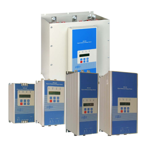
5 • Te chnica l Da ta TECHNICAL DATA Introduction The RVS-DX is a third generation, highly sophisticated and reliable starter designed for use with standard three-phase, three-wire, squirrel cage, induction motors. It provides the best method of reducing current and torque during motor starting. The RVS-DX starts the motor by supplying a slowly increasing voltage, providing soft start and smooth acceleration, while drawing the minimum current necessary to start the motor. -
Page 6: Mains Voltage (Line To Line)
6 • Te chnica l Da ta Mains Voltage (line to line) 3.3.2 Four Main Voltage levels are available: 400V, 480V, 600V and 690V (690V only available for RVS-DX 390A and up). Note: 400V applies for 230 to 400V. Control Voltage 3.3.3 The Control Voltage (terminals A1(~) –... -
Page 7: Ordering Information
7 • Te chnica l Da ta Ordering Information 3.3.6 RVS-DX 400- 230- Full load Mains Voltage Control Options Front Panel Current Voltage Full load Current Specify Description Starter’s 8, 17, 31, 44, 58, 72, 85, 105, 145, 170, 210, 310, 390, 460, 580, 650, 820, 950, 1100 FLC [A] Mains Voltage Specify... -
Page 8: Recommended Wiring Scheme
8 • Re comme nde d Wiring S che me RECOMMENDED WIRING SCHEME Typical wiring diagram Notes: (1) - Use fuses for type 2 coordination. Refer to section 4.3.1 on page 10 (2) - For Aux. input programming refer to section 7.6.9 on page 42 The use of solid state relays to control the digital inputs B1 and C1 is prohibited (3) - For Aux. -
Page 9: Power Wiring Scheme For "Inside-Delta" Connection
9 • Re comme nde d Wiring S che me Power wiring scheme for “Inside-Delta” Connection (Refer to section 4.3.9 on page 12) Connecting RVS-DX INSIDE DELTA Reverse speed with RVS-DX connected INSIDE DELTA. Notes: When installing the RVS-DX INSIDE DELTA. it is highly recommended to use a line contactor (C1) or INSIDE DELTA. -
Page 10: Short Circuit Protection
10 • Re comme nde d Wiring S che me Power factor correction capacitors and overvoltage devices must not be installed on starters load side. When required, install capacitors or overvoltage devices on starter’s line side. Short Circuit Protection 4.3.1 For “class 2 coordination”, protect the starter against a short circuit by thyristor Protection Fuses for I²t and fuses as in dictated in the following table: Max. -
Page 11: Aux. Input (Terminal C1)
11 • Re comme nde d Wiring S che me 4.3.5 Aux. Input (terminal C1) Input from a maintained contact, connected between terminals A2 and C1 to operate as programmed input. Aux. Input can be programmed as one of six options: (1) Dual Adjust (2) Generator Function (3) Slow Speed / Reverse... -
Page 12: Rs-485 Communication (Option # 3M) (Terminals Out(-),Out(+))
12 • Re comme nde d Wiring S che me For thermistor input programming refer to section 7.6.8 on page 40. Ground Terminal (terminal Gnd) Connect thermistor and / or Analogue output shield to this ground terminal. Analogue Output ( terminals Out (+), Out (-)) Dip switches allow selection between: 0-10VDC, 0-20mA, 4-20mA Analogue value can be programmed via the key pad in I/O PROGRAMMING PARAMETERS page to one of the values as follows: (refer to section 7.6.9 on page 42.) -
Page 13: Notes On "Inside Delta" Connection
13 • Re comme nde d Wiring S che me 4.3.9.2 Notes on “Inside Delta” connection • “Inside Delta” requires 6-wire to the motor. • Wrong motor connection will cause serious damage to the motor windings. • When installing the RVS-DX “inside delta” it is highly recommended to use a contactor in series to the RVS-DX or upstream (after motor protection) in order to avoid a destruction of the motor in case of a shorted SCR in the RVS-DX. -
Page 14: Dimensions
14 • Dime ns ions DIMENSIONS RVS-DX 58, 72 RVS-DX 8, 17, 31, 44 Note: Mains voltage terminals: 16mm RVS-DX 85, 105 RVS-DX 145, 170 RVS-DX 210 ________________________________________________________________________________________... - Page 15 15 • Dime ns ions RVS-DX 310 RVS-DX 390 ___________________________________________________________________________________________...
- Page 16 16 • Dime ns ions RVS-DX 460 RVS-DX 580 ________________________________________________________________________________________...
- Page 17 17 • Dime ns ions RVS-DX 650-820 RVS-DX 950-1100 ___________________________________________________________________________________________...
-
Page 18: Installation
18 • Ins ta lla tion INSTALLATION WARNING! Do not interchange line and load connections P rior to Installation 8 9 B Check that Motor’s Full Load Ampere (FLA) is lower than, or equal, to the starter’s Full Load Current (FLC) and that Mains and Control voltages are as indicated on the starter’s side label. -
Page 19: Additional Ventilation
19 • Ins ta lla tion Total heat dissipation [Watt] – The total heat dissipation of the starter and other control devices in the enclosure. If starter is frequently started, average power should be used. 6.3.2 Additional Ventilation Use the following arrangement for forced ventilation of the RVS-DX’s enclosure: Outlet Inlet RVS-DX... -
Page 20: Control Keypad
20 • Control Ke ypa d CONTROL KEYPAD The control keypad is the link between the Soft Starter and the user. The RVS-DX control keypad features: (1) Two lines of 16 alphanumeric characters each (with five selectable languages – English, French, German, Spanish and Turkish) (2) Six push-buttons (Mode, Reset, Select, Store, Up (▲) and down (▼) keys). -
Page 21: Status Leds
21 • Control Ke ypa d Status LEDs. Green Lights when Control Supply voltage is connected to the RVS-DX. Lights during soft start and soft stop process, indicating that motor supply voltage is Yellow Ramp ramping up or down. Lights after completion of starting process, indicating that motor is receiving full Green voltage. -
Page 22: Obtain Default Parameters
22 • Control Ke ypa d Obtain Default Parameters 7.5.3 Press the Mode and ▼ keys simultaneously. The LCD will display: TEST/MAINTENANCE ***OPTIONS*** Press the Select key three times. The LCD will display: STORE ENABLE DEFAULT PARAMET. Press the Store + Mode keys simultaneously. The LCD will display: DATA SAVED OK And after a few seconds the LCD will display:... -
Page 23: Calibrate Voltage, Current And (Factory Use Only!)
23 • Control Ke ypa d 7.5.5 Calibrate Voltage, Current and (Factory Use Only!) Press the Mode and ▼ keys simultaneously. the LCD will display: TEST/MAINTENANCE ***OPTIONS***. Press the Select key five times. The LCD will display: VOLTAGE ADJUST. X VOLT Press the Select key. -
Page 24: Overview Of All Mode Pages And Factory Defaults
24 • Control Ke ypa d Overview of All Mode Pages and Factory Defaults 7.6.1 Appears only in MAXIMIZED MODE % OF MOTOR FLA MAIN PARAMETERS START PARAMETERS STOP PARAMETERS DUAL ADJUSTMENT PARAMETERS Refer page 26 Refer page 27 Refer page 31 Refer page 35 Refer page 37 AMP. - Page 25 25 • Control Ke ypa d Appears only in Appears only in Appears only in Appears only in MAXIMIZED MODE MAXIMIZED MODE MAXIMIZED MODE MAXIMIZED MODE SPECIAL FEATURES FAULT PARAMETERS I/O PROGRAMMING COMM. PARAMETERS STATISTICAL DATA PARAMETERS PARAMETERS Refer page 38 Refer page 40 Refer page 42 Refer page 44...
-
Page 26: Display Mode
26 • Control Ke ypa d Display Mode – page 0 7.6.2 % OF MOTOR FLA Displays in MINIMIZED MODE and MAXIMIZED MODE (Refer to section 7.6.3 page 27) Display and default Range Description values % OF MOTOR FLA Displays operating current as a percentage of motor FLA (Full I<0.1 FLC Load Ampere). -
Page 27: Main Parameters
27 • Control Ke ypa d 7.6.3 Main Parameters – page 1 MAIN PARAMETERS Displays in MINIMIZED MODE and MAXIMIZED MODE - **** - (Refer below for changing modes) Display and default Range Description Remarks values LANGUAGE: SPANISH Sets Starter’s ENGLISH GERMAN language... - Page 28 28 • Control Ke ypa d MAIN PARAMETERS Displays in MINIMIZED MODE and MAXIMIZED MODE - **** - (Refer below for changing modes) Display and default Range Description Remarks values UNDER CURRENT TRIP protection O/C – SHEAR PIN 100-300% of Sets OVER becomes operational when starter is energized 200% OF FLA...
- Page 29 29 • Control Ke ypa d MAIN PARAMETERS Displays in MINIMIZED MODE and MAXIMIZED MODE - **** - (Refer below for changing modes) Display and default Range Description Remarks values UNDERVOLT. DELAY 1–10sec. Sets Note: 5 SEC. UNDERVOLT Becomes operational only after Start signal. TRIP DELAY.
-
Page 30: Tripping Curves Of The Integrated Overload Protection
30 • Control Ke ypa d 7.6.3.1 Tripping Curves of the Integrated Overload Protection The RVS-DX allows motor protection according to IEC class 10 or 20 OR according to NEMA class 10, 20, or NEMA & IEC Class OVERLOAD curves NEMA Class 10 IEC Class 10 10000... -
Page 31: Start Parameters
31 • Control Ke ypa d 7.6.4 S tart Parameters – page 2 1 3 0 B Displays in MINIMIZED MODE and MAXIMIZED MODE START PARAMETERS - **** - (refer to section 7.6.3 on page 27 for changing mode) Display and default Range Description Remarks... - Page 32 32 • Control Ke ypa d START PARAMETERS Displays in MINIMIZED MODE and MAXIMIZED MODE - **** - (refer to section 7.6.3 on page 27 for changing mode) SETTING as Note: described in When INITIAL VOLTAGE is set above section 7.6.7 50% (it’s maximum value), display page 38.
- Page 33 33 • Control Ke ypa d START PARAMETERS Displays in MINIMIZED MODE and MAXIMIZED MODE - **** - (refer to section 7.6.3 on page 27 for changing mode) extended to 1- motor. It is recommended to set 90sec. by using ACCELERATION TIME to the minimum the WIDER acceptable value (approx.
-
Page 34: Soft Start Parameters
34 • Control Ke ypa d Soft start parameters 7.6.4.1 The RVS-DX incorporates 4 “Starting Curves”, enabling selection the suitable torque curve: Start Curve 0 – Standard curve (Default). The most stable and suitable curve for the motor, preventing prolonged starting and motor overheating. Note: When RVS-DX is connected “Inside-Delta”, only CURVE 0 is applied. -
Page 35: Stop Parameters
35 • Control Ke ypa d 7.6.5 Stop Parameters – page 3 STOP PARAMETERS Displays in MINIMIZED MODE and MAXIMIZED MODE - **** - (refer to section 7.6.3 on page 27 for changing mode) Display and default Range Description Remarks values SOFT STOP CURVE 4 (TORQUE) - Page 36 36 • Control Ke ypa d It is recommended that for all standard applications (not pumps), Stop Curve 0 will be used. To reduce Water Hammer select STOP CURVE 1, than 2 or 3, if necessary. Curve 4 - Torque Curve - Provides linear deceleration of the torque. In certain loads, linear torque deceleration can result in close to linear speed deceleration.
-
Page 37: Dual Adjustment Parameters
37 • Control Ke ypa d 7.6.6 Dual Adjustment Parameters – page 4 DUAL ADJUSTMENT Displays in MAXIMIZED MODE only PARAMETERS (refer to section 7.6.3 on page 27 for changing mode) Display and default Description Remarks values When selecting GEN. START/STOP in mode I/O PROGRAMMING PARAMETERS on page PROG. -
Page 38: Special Features Parameters
38 • Control Ke ypa d Special features Parameters – page 5 7.6.7 SPECIAL FEATURES Displays in MAXIMIZED MODE only PARAMETERS (refer to section 7.6.3 on page 27 for changing mode) Display and default Range Description Remarks values SLOW SPEED TORQ. 1(MIN.) –... -
Page 39: Wider Settings Parameters
39 • Control Ke ypa d 7.6.7.1 WIDER SETTINGS Parameters: Parameter WIDER SETTINGS Disabled WIDER SETTINGS Enabled INITIAL VOLTAGE 10-50% -80% CURRENT LIMIT 100-400% 100-500% ACCELERATION TIME 1-30 seconds 1-90 seconds DECELERATION TIME 0-30 seconds 0-90 seconds MAX. START TIME 1-30 seconds 1-250 seconds PHASE LOSS Y/N... -
Page 40: Fault Parameters
40 • Control Ke ypa d Fault Parameters – page 6 7.6.8 FAULT PARAMETERS Displays in MAXIMIZED MODE only - **** - (refer to section 7.6.3 on page 27 for changing mode) Display and default Range Description Remarks values PHASE LOSS Y/N Sets PHASE PHASE LOSS protection trips the RVS-DX LOSS trip... - Page 41 41 • Control Ke ypa d FAULT PARAMETERS Displays in MAXIMIZED MODE only - **** - (refer to section 7.6.3 on page 27 for changing mode) Display and default Range Description Remarks values CURRENT page 27 for details on adjusting UNDER RESET time CURRENT TRIP) delay.
-
Page 42: I/O Programming Parameters
42 • Control Ke ypa d I /O Programming Parameters – page 7 7.6.9 1 3 5 B I/O PROGRAMMING Displays in MAXIMIZED MODE only PARAMETERS (refer to section 7.6.3 on page 27 for changing mode) Display and default Range Description Remarks values... -
Page 43: Prog. Input C1
43 • Control Ke ypa d 7.6.9.1 PROG. INPUT C1 Terminal C1 can be programmed to operate in various modes: TERMINAL C1 Description programmed function START/STOP C1 is a maintained stop input to the RVS-DX, while B1 is a momentary start input to the RVS-DX. -
Page 44: Comm. Parameters - Page 8- Applicable With Optional Modbus & Devicenet Comm
44 • Control Ke ypa d C omm. Parameters – page 8- Applicable with Optional Modbus & DeviceNet Comm. 7.6.10 1 3 6 B N ote: When DeviceNet option is required an external unit, DeviceNet to Modbus Gateway is required. This 5 3 B gateway is connected via 2 wires to the optional Modbus terminals. -
Page 45: Comm. Parameters - Page 8 - Applicable With Optional Profibus Comm
45 • Control Ke ypa d 7.6.11 Comm. Parameters – page 8 - Applicable with Optional Profibus Comm. COMM.PARAMETERS Displays in MAXIMIZED MODE only - **** - (refer to section 7.6.3 on page 27 for changing mode) Display and default Range Description values... -
Page 46: Statistical Data
46 • Control Ke ypa d S tatistical Data – page 9 7.6.12 1 3 8 B STATISTICAL DATA Displays in MINIMIZED MODE and MAXIMIZED MODE - **** - (refer to section 7.6.3 on page 27 for changing mode) Display and default Range Description values... -
Page 47: Phase Sequence
47 • Control Ke ypa d 7.7.2 Phase Sequence Becomes operational when starter is energized, provided this protection has been activated, trips the starter when phase sequence is wrong. Refer to section 7.6.8 on page 40 parameter PHASE SEQ. Y/N. 7.7.3 Shorted SCR or Wrong Connections Becomes operational after start signal. -
Page 48: Timing Occurrence Table
48 • Control Ke ypa d Timing Occurrence Table Active During Timing And Occurrence Soft Start Stop Stop √ Too many starts with Start Inhibit period √ √ Electronic Overload with Curve selection O/C Shear Pin (Jam) √ √ √ Starter Protection –... -
Page 49: Starting Procedure
49 • S TARTING P ROCEDURE STARTING PROCEDURE Note: It is necessary to connect a motor to load terminals otherwise S.SCR or WRONG CONNECTION Protection is activated. Other loads such as light bulbs, resistors, etc. may also cause WRONG CONNECTION Fault. When mains voltage is connected to the RVS-DX, even if control voltage is disconnected, full voltage may appear on the starter load terminals. -
Page 50: Standard Starting Procedure
50 • S TARTING P ROCEDURE Standard starting procedure Connect Control Supply. On LED will lit. Review all parameters with Mode and Select keys Set parameters as required. If necessary, return to Default Parameters (see “Service Mode”). Connect mains voltage to starter’s line terminals. Set LCD to show “MOTOR FLA”... -
Page 51: Examples Of Starting Curves
51 • S TARTING P ROCEDURE Apply Start command If acceleration time is too short, increase ACC. Motor acceleration time TIME setting and/or decrease CURRENT LIMIT. to full speed is as (when decreasing CURRENT LIMIT, make sure required? motor increases speed gradually and does not stall). -
Page 52: Special Starting - Using Dual Adjustment
52 • S TARTING P ROCEDURE Special starting – Using Dual Adjustment 8.3.3 For using DUAL ADJUSTMENT automatically, connect AUX. RELAY in series to Aux. Input as shown in section 8.3.3.1 on page 53. Program PROG. AUX. RELAY to IMMEDIATE and program RELAY ON DELAY to tx. Program PROG. -
Page 53: Special Starting - Using Dual Adjustment - Wiring Scheme
53 • S TARTING P ROCEDURE 8.3.3.1 Special starting – Using Dual Adjustment – wiring scheme Notes: (1) - Program PROG. INPUT C1 to DUAL ADJUST (2) - Program PROG. AUX. RELAY to IMMEDIATE and program RELAY ON DELAY to tx. Refer to section 7.6.9 on page 42 for details on I/O programming. -
Page 54: Stopping Curve
54 • S TARTING P ROCEDURE 8.3.4.2 Stopping Curve Adjust MAIN PARAMETERS as necessary (FLA, FLC, etc..) Set STOP CURVE and DECELERATION TIME, to their default values (curve 0, 10 sec., respectively). Stop the pump, watching the pressure gauge and check valve as the pump stops. Look for overshooting (“Water Hammer”) of the gauge (abruptly stops the pump and the motor). -
Page 55: Trouble Shooting
55 • TROUBLE S HOOTING TROUBLE SHOOTING Upon fault – motor stops, Fault LED lights and Fault Relay operates. The LCD shows TRIP: and fault description. (for example: TRIP: UNDER CURRENT). Fault Massage Cause and trouble shooting TOO MANY Trips the starter if number of starts, during START PERIOD exceeds the preset STARTS number. - Page 56 56 • TROUBLE S HOOTING Fault Massage Cause and trouble shooting UNDER Trips the starter when line current drops below the preset level for the preset time. CURRENT Check UNDER CURRENT TRIP and TIME DELAY settings, check line currents through L1, L2, L3. For more information on UNDER CURRENT settings refer to section 7.6.3 on page 27 (MAIN PARAMETERS).
- Page 57 57 • TROUBLE S HOOTING Fault Massage Cause and trouble shooting Heat-sink over-temperature. Trips the starter when heat-sink temp. rises above 85˚C. OVER TEMPERATURE Check that motor starting is not too frequent. EXTERNAL Trips the starter when a N.O contact between Aux. input terminals 13, 14 closes for FAULT over two seconds.
-
Page 58: Blank Rma Form
Current Limit Remarks By Distributor: We declare that product has been correctly Warranted repair/replacement applied, installed and operated, in accordance with Solcon’s written instructions, appropriate codes, regulations and good practice, within the limits of rated capacity and normal usage. ________________________________________________________________________________________... -
Page 59: Technical Specifications
59 • TECHNICAL S P ECIFICATIONS : TECHNICAL SPECIFICATIONS: Supply Voltage Line to Line 230-600V (to be specified) + 10%-15% for all models Line to Line 690V (to be specified) + 10%-15% for RVS-DX 390A and up Frequency 45 – 65 Hz (Fixed or variable frequency source) Control Supply 115V or 230V (to be specified) +10% - 15% Load... - Page 60 20VA 20VA 20VA 20VA 20VA 20VA 20VA 30VA 30VA 20VA 30VA 30VA 20VA 600VA 40VA 20VA 800VA 40VA 20VA 1700VA 40VA 20VA 1700VA 40VA 20VA 2400VA 60VA 1100 20VA 2400VA 60VA Notes: Solcon Industries Ltd. www.solcon.com; Technical support: office@solcon.com ________________________________________________________________________________________...
Need help?
Do you have a question about the RVS-DX Series and is the answer not in the manual?
Questions and answers