
Related Manuals for Lenze AC Tech SMVector

Summary of Contents for Lenze AC Tech SMVector
- Page 1 CMVCAN01A SMVector - CANopen Communication Module Communications Interface Reference Guide...
- Page 2 About these instructions This documentation applies to the CANopen communications option for the SMVector inverter and should be used in conjunction with the SMVector Operating Instructions (Document SV01) that shipped with the drive. These documents should be read carefully as they contain important technical data and describe the installation and operation of the drive and this option.
-
Page 3: Table Of Contents
Contents Safety information ..............2 Introduction ................4 Overview ....................4 2.2 SMVector CANopen Implementation Specifications ........4 Installation ................5 Installing the Module into the Terminal Cover ..........5 CANopen terminal block ................5 Installing the Terminal Cover ..............6 Commissioning CANopen communications .....7 Quick Set-up .....................7 Extended Parameters for CANopen ........8... -
Page 4: Safety Information
Safety information Safety information General Some parts of Lenze controllers (frequency inverters, servo inverters, DC controllers) can be live, moving and rotating. Some surfaces can be hot. Non-authorized removal of the required cover, inappropriate use, and incorrect installation or operation creates the risk of severe injury to personnel or damage to equipment. - Page 5 Safety information DANGER! • After the controller has been disconnected from the supply voltage, live components and power connection must not be touched immediately, since capacitors could be charged. Please observe the corresponding notes on the controller. • Do not continuously cycle input power to the controller more than once every three minutes.
-
Page 6: Introduction
DSP402 compatible control and status words are available to the user for configuring modes of operation and altering the drive operating parameters. Additionally, to offer greater interoperability with the SMVector inverter, a drive specific set of objects are available that offer further drive profile configuration and allow access to specific modes of operation. -
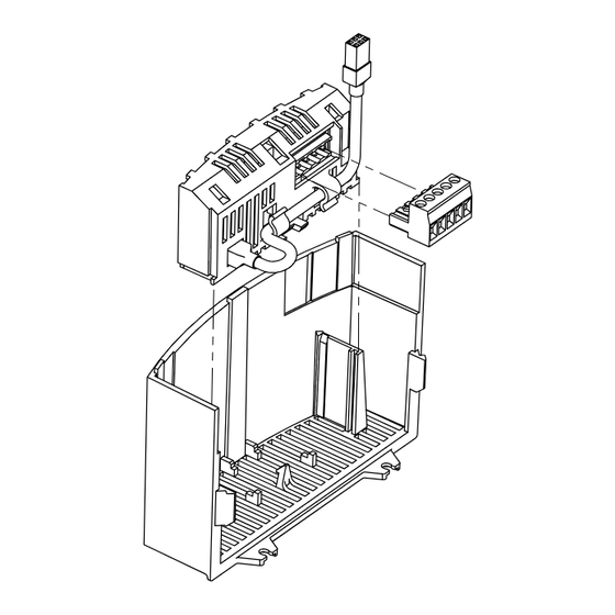
Page 7: Installation
Installation Installation Installing the Module into the Terminal Cover 1 2 3 4 5 0.5 Nm/ 4.5 lb-in < _ 2.8 mm² (12-22 AWG) CANopen terminal block Terminal Description Important For reliable communication make sure terminal CAN_GND is connected to CAN network CAN_GND: CAN earth ground GND/common. -
Page 8: Installing The Terminal Cover
Installation Installing the Terminal Cover ENGLISH... -
Page 9: Commissioning Canopen Communications
Commissioning Commissioning CANopen communications Following installation of the CANopen communications module, Quick Set-up With drive power disconnected connect the CANopen communication module and network cable to the drive as shown in the preceding section. NOTE: If CANopen network is already operational do NOT connect the network connector until the Node ID and Baud rate parameters on installed drive are setup correctly. -
Page 10: Extended Parameters For Canopen
Commissioning Extended Parameters for CANopen In addition to the drive parameters (detailed in the Installation and Operation manual that accompanied the drive), the installation of the CANopen module will give access to the 400 series parameters that are exclusively for the CANopen communications module. Parameter menu Code Possible Settings... - Page 11 Commissioning Code Possible Settings IMPORTANT Name Default Selection CANopen / System bus parameters CAN address 127 If P413 = 0, 1: maximum setting = 63 P410 (Node ID) CAN baud rate 0 10 kbps (max distance = 5000m) P411 1 20 kbps (max distance = 2500m) 2 50 kbps (max distance = 1000m) 3 125 kbps (max distance = 500m) 4 250 kbps (max distance = 250m)
- Page 12 Commissioning Code Possible Settings IMPORTANT Name Default Selection CANopen status Not initialized • Read-only P419 • Note: RPDOs and TPDOs are only Initializing active in operational state (P419 = 5) Stopped Pre-operational reserved Operational Guard time {ms} 65535 • P420 x P421 = node life time P420 •...
- Page 13 Commissioning Code Possible Settings IMPORTANT Name Default Selection CAN Peripheral Bits: • Read-only P429 Status • CAN warnings and errors Error passive mode Bus off mode CAN Enabled Receiver busy Transmitter busy Transmit error count > 128 Overload frame Receive error count > 128 ENGLISH...
- Page 14 Commissioning Code Possible Settings IMPORTANT Name Default Selection RPDO#1 configuration parameters RPDO#1 COB ID 2047 If P413 = 0, 2: Setting will change to P440 512 + Node ID during power-up or P418 reset. RPDO#1 0 Disable P441 enable/disable 1 Enable WARNING! CAN re-initialization may activate new RPDO configurations, which can result in changes to present controller state, including starting.
- Page 15 Commissioning Code Possible Settings IMPORTANT Name Default Selection RPDO#2 configuration parameters RPDO#2 COB ID 2047 If P413 = 0, 2: Setting will change to P450 768 + Node ID during power-up or P418 reset. RPDO#2 0 Disable P451 enable/disable 1 Enable WARNING! CAN re-initialization may activate new RPDO configurations, which can result in changes to present controller state, including starting.
- Page 16 Frequency + PID Setpoint 4 Drive Status Word + Actual Torque Setpoint: 0…400% Frequency + Torque Setpoint 5 Status Word matches the drives Setting used to control another SMVector Control Word Drive. See Appendix A1.1. TPDO#1 WORD0 65535 65535 •...
- Page 17 Frequency + PID Setpoint 4 Drive Status Word + Actual Torque Setpoint: 0…400% Frequency + Torque Setpoint 5 Status Word matches the drives Setting used to control another SMVector Control Word Drive. See Appendix A1 - Example 1. TPDO#2 WORD0 65535 65535 •...
- Page 18 Commissioning Code Possible Settings IMPORTANT Name Default Selection CANopen Module Specific parameters Communication • Read only P495 Module software • Alternating Display: xxx-; -yy version Missed Messages • Read only P498 Drive to Module Missed Messages • Read only P499 Module to Drive ENGLISH...
-
Page 19: Canopen Mapping Details
Commissioning CANopen mapping details The tables in the following sections may use descriptions from the CANopen DSP 402 standard. This terminology should not be interpreted as referring to drive hardware. 5.2.1 RPDO mapping details (P446/P456) P446 / P456 setting = 0 P446 / P456 setting = 1 Output Switch Output Switch... - Page 20 Commissioning P446 / P456 setting = 2 P446 / P456 setting = 3 Run Forward Run Forward 0 = NOT Run Forward 1 = Run Forward 0 = NOT Run Forward 1 = Run Forward Run Reverse Run Reverse 0 = NOT Run Reverse 1 = Run Reverse 0 = NOT Run Reverse 1 = Run Reverse...
- Page 21 Commissioning P446 / P456 setting = 4 Run Forward 0 = NOT Run Forward 1 = Run Forward Run Reverse 0 = NOT Run Reverse 1 = Run Reverse Fault Reset: on transition from 0 to 1 Reserved Reserved Control 0 = Local Control 1 = Network Control Speed Reference...
-
Page 22: Tpdo Mapping Details (P466/P476)
Commissioning 5.2.2 TPDO mapping details (P466/P476) P466 / P476 setting = 0 P466 / P476 setting = 1 Ready Ready 0 = Not ready to switch on 1 = Ready to switch on 0 = Not ready to switch on 1 = Ready to switch on Output Switch Output Switch 0 = switch OFF... - Page 23 Commissioning P466 / P476 setting = 2 P466 / P476 setting = 3 Drive Fault Drive Fault 0 = No Fault 1 = Faulted 0 = No Fault 1 = Faulted Reserved Reserved Run Forward Run Forward 0 = NOT Run Forward 1 = Run Forward 0 = NOT Run Forward 1 = Run Forward...
- Page 24 Commissioning P466 / P476 setting = 5 P466 / P476 setting = 4 (Special for Daisy Chaining) Drive Fault Run Forward 0 = No Fault 1 = Faulted 0 = NOT Run Forward 1 = Run Forward Run Reverse Reserved 0 = NOT Run Reverse 1 = Run Reverse Run Forward...
-
Page 25: Troubleshooting And Fault Elimination
Troubleshooting and fault elimination Troubleshooting and fault elimination Faults Status Cause Remedy f.ntf Module to Drive communication Connection between drive and Check cable and connection time out module is not made. between module and drive F.nF1 Guard Time Fault See parameters P420, P421, P423 F.nF2 Message Monitoring time-out See parameters P425, P426... -
Page 26: A1 Appendix A - Configuration Example
Appendix Appendix A - Configuration Example A1.1 Master / Follower drive system The following example shows how to set up for a typical “Master - Follower” drive system using CANopen as the link between the two drives. The “Master” drive can be controlled by CANopen or by traditional control elements (relays, switches, potentiometers, etc.), the “Follower”... - Page 27 Appendix After setting the parameters, perform Node reset using parameter P418 or cycle the power. NOTE: ANY time the PDO modes or addresses are changed, they must be either disabled/enabled (using P441 or P451) or the drive must be reset by cycling power. After these controllers are configured as above, the “Follower”...
- Page 28 AC Technology Corporation • 630 Douglas Street • Uxbridge, MA 01569 • USA +1 (508) 278-9100 www.actech.com Document CMVCAN01A...
Need help?
Do you have a question about the SMVector and is the answer not in the manual?
Questions and answers