
Related Manuals for Yamaha FX SHO WaveRunner 2013


Summary of Contents for Yamaha FX SHO WaveRunner 2013
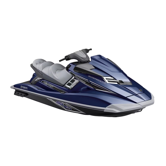
- Page 1 2013 WaveRunner FX SHO FX Cruiser SHO OWNER’S/OPERATOR’S MANUAL Read this manual carefully before operating this watercraft. F2S-F8199-71-E0...
- Page 2 Read this manual carefully before operating this watercraft. This manual should stay with the WaveRunner if it is sold.
- Page 3 (are) in conformity with the type(s) for which above mentioned EC type-examination certificate(s) has (have) been issued. H. Yamaji / President of YAMAHA MOTOR EUROPE N.V. Name / Title: (identification of the person empowered to sign on behalf of the engine manufacturer or his authorised representative)
- Page 4 Important manual information EJU30192 EJU40410 To the owner/operator Thank you for choosing a Yamaha watercraft. Because Yamaha has a policy of continuing This owner’s/operator’s manual contains in- product improvement, this product may not be formation you will need for proper operation, exactly as described in this owner’s/opera-...
-
Page 5: Table Of Contents
Watercraft control functions ..26 Fuel requirements ......58 Remote control transmitter ....26 Fuel ..........58 Yamaha Security System ....27 Engine oil requirements ....60 Engine stop switch ......28 Engine oil ......... 60 Engine shut-off switch ..... 28 Draining the bilge water .... - Page 6 Table of contents Transporting on a trailer ....63 Rustproofing ........93 Maintenance ........94 First-time operation......64 Maintenance ........ 94 Engine break-in ......64 Tool kit ..........94 Removing and installing the engine Pre-operation checks...... 65 cover ..........94 Pre-operation checklist ....
-
Page 7: General And Important Labels
Craft Identification Number (CIN), and engine serial number in the spaces pro- vided for assistance when ordering spare parts from a Yamaha dealer. Also record and keep these ID numbers in a separate place in case your watercraft is stolen. -
Page 8: Manufactured Date Label
General and important labels EJU42030 EJU30320 Manufactured date label Model information This label is attached to the top of the cylinder EJU30331 Builder’s plate head. (See page 49 for seat removal and in- Watercraft with this label conform to certain stallation procedures and page 94 for engine portions of the European Parliament directive cover removal and installation procedures.) - Page 9 General and important labels TIP: The significant wave height is the mean height of the highest one-third of the waves, which approximately corresponds to the wave height estimated by an experienced observer. However, some waves will be double this height.
-
Page 10: Important Labels
General and important labels EJU30452 Important labels Read the following labels before using this watercraft. If have any questions, consult a Yamaha dealer. -
Page 11: Warning Labels
General and important labels EJU35913 Warning labels If any of these labels are damaged or missing, contact a Yamaha dealer for replacements. - Page 12 General and important labels...
- Page 13 General and important labels...
- Page 14 General and important labels...
-
Page 15: Other Labels
General and important labels EJU36261 Other labels... - Page 16 General and important labels The following label indicates the correct direction to upright a capsized watercraft. The following CE marking is located on the back of the remote control transmitter.
-
Page 17: Safety Information
Limitations on who may The safe use and operation of this water- operate the watercraft craft is dependent upon the use of proper Yamaha recommends a minimum operator ● riding techniques, as well as upon the age of 16 years old. -
Page 18: Cruising Limitations
Safety information kles, and other bones. Do not jump wakes EJU30761 Cruising limitations or waves. Scan constantly for people, objects, and ● Do not operate the watercraft in rough wa- ● other watercraft. Be alert for conditions that ter, bad weather, or when visibility is poor; limit your visibility or block your vision of this may lead to an accident causing injury others. -
Page 19: Operation Requirements
Safety information with another boat, which could result in se- EJU30821 Operation requirements vere injury or death. All riders must wear a personal flotation de- ● vice (PFD) that is approved by the appropri- ate authorities and is suitable for personal watercraft use. - Page 20 Safety information certain kinds of accidents and that it could your feet increases the chances of losing injure you in others. your balance, or hitting objects outside the A helmet is designed to provide some head watercraft with your feet. Do not give a ride protection.
-
Page 21: Recommended Equipment
Scan carefully for swimmers and stay away ● be used as an emergency signal. Contact a from swimming areas. Swimmers are hard Yamaha dealer for more information. to see and you could accidentally hit some- Watch ● one in the water. -
Page 22: Hazard Information
Always operate the watercraft in an This model is equipped with the Yamaha open area. Engine Management System (YEMS) that Do not touch the hot muffler or engine dur- includes an off-throttle steering (OTS) sys- ●... - Page 23 Safety information legs, ankles, and other bones. You could any debris or weeds, which may have col- also damage the shift mechanism. lected around the jet intake. Once you are traveling at trolling speed, re- ● verse can be used to slow down or stop dur- ing slow-speed maneuvering, such as when docking.
-
Page 24: Water-Skiing
Safety information is required by law. Let the skier direct the EJU30954 Water-skiing operator’s control of speed and direction You can use the watercraft for water-skiing if with hand signals. it has the seating capacity to carry the opera- The spotter should sit astride the rear of the tor, a rearward-facing spotter, and the water- seat and hold onto the handgrip with both skier when he or she is not skiing. -
Page 25: Safe Boating Rules
Make sure that the rope is not looped EJU30970 Safe boating rules around anything. Your Yamaha watercraft is legally considered After checking that the skier is ready and a powerboat. Operation of the watercraft must that there is no traffic or other obstacles, ap- be in accordance with the rules and regula- ply enough throttle to raise the skier. -
Page 26: Enjoy Your Watercraft Responsibly
Safety information waterways stay open for the enjoyment of a EJU30991 Enjoy your watercraft variety of recreational opportunities. responsibly You share the areas you enjoy when riding your watercraft with others and with nature. So your enjoyment includes a responsibility to treat these other people, and the lands, wa- ters, and wildlife with respect and courtesy. -
Page 27: Description
The left side of the watercraft when facing forward. Bilge water Water that has collected in the engine compartment. Yamaha Engine Management System (YEMS) YEMS is an integrated, computerized management system that controls and adjusts ignition timing, fuel injection, engine diagnostics, and the off-throttle steering (OTS) system. -
Page 28: Location Of Main Components
Description EJU31011 Location of main components Exterior 1 Fuel filler cap (page 58) 2 Hood 3 Handlebars 4 Rear seat (page 49) 5 Front seat (page 49) 6 Footwell 7 Bow eye (page 51) 8 Hull 9 Cooling water pilot outlet (page 30) 10 Pull-up cleat (FX Cruiser SHO) (page 52) 11 Gunwale... - Page 29 Description 1 Boarding platform 13 Intake grate 2 Reboarding grip (page 50) 14 Flushing hose connector 3 Stern storage compartment (page 54) 4 Cleat (page 51) 5 Handgrip (page 50) 6 Reboarding step (page 50) 7 Reverse gate (page 32) 8 Jet thrust nozzle 9 Ride plate 10 Stern drain plug (page 61)
- Page 30 Description 12 13 14 18 19 20 21 22 1 Built-in watertight storage compartment 20 Tilt lever (page 30) (page 55) 21 Shift lever (page 32) 2 Start switch (page 28) 22 “NO-WAKE MODE” switch (page 36) 3 Engine shut-off switch (page 28) 23 “SET”...
- Page 31 Description Engine compartment 1 Engine cover 2 Air filter case 3 Water separator (page 31) 4 Fuel tank 5 Battery (page 68) 6 Electrical box 7 Spark plug/Spark plug cap/Ignition coil 8 Removable watertight storage compartment (page 55) 9 Engine oil filler cap (page 60) 10 Dipstick (page 60)
-
Page 32: Control Function Operation
Watercraft control functions lost. EJU42550 Remote control transmitter The Yamaha Security System and Low RPM Mode settings can be selected by operating the remote control transmitter. (See page 27 for Yamaha Security System setting proce- dures and page 35 for Low RPM Mode activa- tion procedures.) -
Page 33: Yamaha Security System
The Yamaha Security System settings can only be selected while the engine is stopped. EJU36775 Yamaha Security System settings The Yamaha Security System settings will be confirmed by the number of beeps when the 1 Lock button remote control transmitter is operated, and by 2 “UNLOCK”... -
Page 34: Engine Stop Switch
Control function operation EJU31152 accidental starting or unauthorized operation Engine stop switch “ ” by children or others. The engine stop switch (red button) stops the engine when the switch is pushed. EJU42320 Start switch “ ” 1 Engine stop switch ECJ01310 NOTICE EJU31163... -
Page 35: Throttle Lever
This model is equipped with the Yamaha En- gine Management System (YEMS) that in- cludes an off-throttle steering (OTS) system. -
Page 36: Adjustable Tilt Steering System
Control function operation in response to handlebar input until you apply (2) Make sure that the tilt lever returns to its throttle again or you reach trolling speed. original position and that the handlebars EJU31293 are securely locked in place. Adjustable tilt steering system The position of the handlebars can be adjust- ed back and forth by operating the tilt lever. -
Page 37: Water Separator
Control function operation Water discharge may not be constant when watercraft, be sure to wipe it up with a dry ● the engine is running at idling speed. If this cloth. occurs, apply a little throttle to make sure (3) Securely tighten the drain screw until it that water discharges properly. -
Page 38: Watercraft Operation
Watercraft operation EJU40011 er and the watercraft will start moving in Watercraft operation functions reverse at trolling speed. EJU42492 Shift system EWJ01230 WARNING Do not use the reverse function to slow ● down or stop the watercraft as it could cause you to lose control, be ejected, or impact the handlebars. -
Page 39: Quick Shift Trim System (Q.s.t.s.)
Watercraft operation pecially if the Q.S.T.S. selector is not also (2) Squeeze the shift lock lever and push the in the neutral position. shift lever forward until it stops in the for- ward position. The reverse gate will rise completely and the watercraft will start moving forward at trolling speed. - Page 40 Watercraft operation There are 5 positions: neutral, 2 bow-down TIP: positions (a) and (b), and 2 bow-up positions The watercraft performance characteristics (c) and (d). according to the trim angle change depending on the operating conditions. 1 Q.S.T.S. selector Bow-down positions (a) and (b) To change the trim angle: The bow will go down, causing the trim angle (1) Reduce engine speed to less than 3000...
-
Page 41: Watercraft Operation Modes
TIP: mode of the Yamaha Security System. Having the Q.S.T.S. selector in a position oth- Activating and deactivating the Low RPM er than neutral may increase the chance of... -
Page 42: No-Wake Mode
Watercraft operation onds. Once the beeper sounds two times and “L- the “UNLOCK” indicator light blinks two times, Number of Low RPM Mode MODE” beeps operation indicator then comes on, the “L-MODE” indicator light light goes off and the Low RPM Mode is deactivat- Comes ed. -
Page 43: Cruise Assist
Watercraft operation To activate the no-wake mode: TIP: (1) Release the throttle lever and let the en- The digital speedometer display blinks contin- gine speed return to idle. ually while the no-wake mode is activated. (2) Make sure that the shift lever is in the for- ward position. - Page 44 Watercraft operation at which the cruise assist was set; releas- TIP: ing the throttle lever will deactivate the The cruise assist can only be set between ● cruise assist. engine speeds of approximately 3000 r/min TIP: and approximately 7000 r/min. The cruise assist cannot be activated in the The digital speedometer display blinks contin- ●...
- Page 45 Watercraft operation the engine will respond normally to the throttle engine speed will change. However, the ad- operation. justment is limited to a maximum of five incre- ments above or below the initial cruise assist setting. To deactivate the cruise assist: Relax your grip on the throttle lever.
-
Page 46: Instrument Operation
3 Multifunction display (FX Cruiser SHO) used as either a speedometer or a tachome- ter. TIP: The analog tachometer is selected at the Yamaha factory. 1 “SPEED/RPM” button 2 “VOLT/HOUR” button 3 “START/STOP” button (FX Cruiser SHO) 4 “MODE/RESET” button (FX Cruiser SHO) -
Page 47: Information Display
Instrument operation To switch to the tachometer from the speed- (See page 41 for information on switching the ometer: digital speedometer display units.) Push the “SPEED/RPM” button for at least 1 second after the multifunction information center is activated. When the meter switches to the analog tachometer function, the “RPM”... - Page 48 Instrument operation miles only, the “SPEED” indicator light blinks TIP: three times. Miles are selected as the display units at the Yamaha factory. 1 “VOLT/HOUR” button 2 “SPEED” indicator light 1 Digital speedometer TIP: Digital speedometer display (mph) The “SPEED” indicator light blinks three times...
- Page 49 Instrument operation Voltmeter TIP: The voltmeter shows the battery voltage. The hour meter is selected at the Yamaha When the battery voltage is normal, the volt- factory. meter displays approximately 12 volts. If the battery voltage has dropped significant- ly, “LO” is displayed on the voltmeter. If the battery voltage has risen significantly, “HI”...
- Page 50 (See page 60 for information on checking the engine oil level.) If the oil level is sufficient, have a Yamaha dealer check the watercraft. TIP: Push any of the operation buttons for the mul-...
-
Page 51: Multifunction Display (Fx Cruiser Sho)
If mediately reduce the engine speed, return to there is no discharge of water, stop the en- shore, and have a Yamaha dealer check the gine, and then check the jet intake for clog- engine. - Page 52 Instrument operation When “mph” are selected as the display units To display the heading: of the digital speedometer, values are shown (1) While pushing the “START/STOP” but- in miles/gallons/degrees Fahrenheit. ton, start the engine. (2) Release the “START/STOP” button brief- ly, and then push the “START/STOP”...
- Page 53 Instrument operation Tripmeter Fuel consumption per hour This display shows the distance traveled in ki- This display shows the current fuel consump- lometers “KM” or miles “MILES” since the tion in liters per hour “L/HR” or gallons per measurement was started. hour “G/HR”.
- Page 54 Instrument operation Water temperature automatically when the displays go off 25 sec- This display shows the ambient water temper- onds after the engine stops. ature “L TEMP” (lake temperature). 1 “START/STOP” button 2 “MODE/RESET” button Air temperature This display shows the ambient air tempera- To start the measurements: ture “E TEMP”...
-
Page 55: Equipment Operation
Equipment operation EJU40333 To install the rear seat: Equipment (1) Insert the projections on the front of the EJU42202 seat into the stays on the deck. Seats The front and rear seats are removable. Remove the seats to access the engine com- partment and removable watertight storage compartment. -
Page 56: Handgrip
Equipment operation (3) Pull the seat rearward and remove it. EJU31363 Handgrip The handgrip is used when boarding the wa- tercraft from the water and when the spotter is facing rearward. WARNING! Do not use the handgrip to lift the watercraft. The hand- grip is not designed to support the water- craft’s weight. -
Page 57: Bow Eye
Equipment operation when released. WARNING! Do not use the towing it in an emergency. (See page 106 for reboarding step to lift the watercraft. The information on towing the watercraft.) reboarding step is not designed to sup- port the watercraft’s weight. If the reboard- ing step breaks, the watercraft could fall, which could result in severe injury. -
Page 58: Pull-Up Cleats (Fx Cruiser Sho)
Equipment operation breaks, the watercraft could fall, which jects that must be kept dry, put them in a wa- could result in severe injury. terproof bag. [EWJ01510] Make sure that the storage compartments are closed securely before operating the water- craft. - Page 59 Equipment operation To close the bow storage compartment: To open the glove compartment: Push the rear of the hood down to securely Turn the glove compartment knob 90° to the lock it in place. left or right, and then lift up the lid. 1 Glove compartment knob To drain water from the bow storage compart- ment:...
- Page 60 Equipment operation To close the glove compartment: EJU42192 Stern storage compartment Lower the lid, and then turn the glove com- The stern storage compartment is located in partment knob to securely lock the lid in place. front of the boarding platform. To open the stern storage compartment: (1) Pull the rear of the stern storage compart- ment latch on both sides of the stern stor-...
- Page 61 Equipment operation (2) Hook the front of the latch on both sides Removable beverage holder The removable beverage holder is located in of the lid onto the hull, and then push the the glove compartment. (See page 53 for in- rear of the latch inward to securely lock it formation on the glove compartment.) in place.
- Page 62 Equipment operation To open the built-in watertight storage com- To open the removable watertight storage partment: compartment: Loosen the cap and remove it. (1) Remove the rear seat. (See page 49 for seat removal and installation proce- dures.) (2) Loosen the cap and remove it. 1 Cap 1 Cap 1 Built-in watertight storage compartment...
-
Page 63: Fire Extinguisher Holder And Cover
Equipment operation EJU42390 hood is securely closed before using the Fire extinguisher holder and cover watercraft. The fire extinguisher holder and cover are lo- cated in the bow storage compartment. To use the fire extinguisher holder and cover: (1) Pull the hood latch rearward, and then lift up the rear of the hood. -
Page 64: Operation And Handling Requirements
Gasoline and gasoline vapors are ex- ● Yamaha does not recommend gasohol con- tremely flammable. To avoid fires and taining methanol because it can cause fuel explosions and to reduce the risk of in-... - Page 65 Operation and handling requirements (5) Loosen the fuel filler cap and remove it. not leave the watercraft with a full tank in direct sunlight. 1 Fuel filler cap 1 Approximately 50 mm (2 in) from top of the (6) Slowly add fuel to the fuel tank. fuel tank Fuel tank capacity: (8) Wipe up any spilled fuel immediately with...
-
Page 66: Engine Oil Requirements
(1) Place the watercraft in a precisely level the maximum level mark, consult a position on land with the engine stopped. Yamaha dealer. If the engine oil level is If the engine was running, allow the en- below the minimum level mark, add en- gine oil to settle by waiting 5 minutes or gine oil. -
Page 67: Draining The Bilge Water
Operation and handling requirements (6) Loosen the engine oil filler cap and re- EJU40021 Draining the bilge water move it. ECJ01301 NOTICE Do not run the engine at full throttle when bilge water remains in the engine compart- ment. The bilge water can splash into the engine, which can result in severe dam- age. -
Page 68: Draining The Bilge Water On Water
Operation and handling requirements maining moisture in the engine compart- engine, which can result in severe dam- ment with a dry cloth. age. [ECJ00553] (4) Securely install the stern drain plugs by tightening them until they stop. NOTICE: Before installing the stern drain plugs, clean the drain plug threads to remove any foreign materials, such as dirt or sand. -
Page 69: Transporting On A Trailer
Operation and handling requirements EJU42430 Transporting on a trailer When transporting the watercraft on a trailer, secure the tie downs to the trailer through the bow eye and stern eyes. NOTICE: Do not at- tach ropes or tie downs to any part of the watercraft other than the bow eye and stern eyes to secure the watercraft to the trailer. -
Page 70: First-Time Operation
First-time operation EJU36665 Engine break-in ECJ00431 NOTICE Failure to perform the engine break-in could result in reduced engine life or even severe engine damage. The engine break-in is essential to allow the various components of the engine to wear and polish themselves to the correct operat- ing clearances. -
Page 71: Pre-Operation Checks
Do not operate the watercraft if you find any prob- lem. If a problem cannot be corrected by the procedures provided in this manual, have the watercraft inspected by a Yamaha dealer. EJU41232 Pre-operation checklist Before using this watercraft, be sure to perform the checks in the following checklist. - Page 72 Pre-operation checks ITEM ROUTINE PAGE Jet intake Check the jet intake for damage and clogging. Check the stern drain plugs for damage and foreign Stern drain plugs material and check that they are securely installed. Hood Check that the hood is securely closed. Front and rear seats Check that the seats are securely installed.
-
Page 73: Pre-Operation Check Points
Pre-operation checks EJU32281 Make sure that there is no damage inside the Pre-operation check points engine compartment. EJU42380 Pre-launch checks Perform the pre-launch checks in the pre-op- eration checklist while the watercraft is on land. To perform the pre-launch checks: (1) Remove the seats and removable water- tight storage compartment. - Page 74 Pre-operation checks water separator, drain it. (See page 31 for in- the dipstick. (See page 60 for information on formation on draining the water separator.) checking the engine oil level.) 1 Water separator 1 Dipstick EJU40181 Engine unit check Check the exterior of the engine unit for dam- age or other problem.
- Page 75 Pre-operation checks aged, obstructed, or not connected prop- whole range, and that the free play is not ex- erly. cessive. [EWJ00451] 1 Breather hose Turn the handlebars as far as possible to the 2 Negative (–) battery terminal: Black lead right and left to make sure that the jet thrust 3 Positive (+) battery terminal: Red lead nozzle moves as the handlebars are turned,...
- Page 76 Pre-operation checks right and left fully turned positions of the jet locked in place. (See page 30 for adjustable thrust nozzle. tilt steering system operation procedures.) EJU32644 Quick Shift Trim System (Q.S.T.S.) checks Operate the Q.S.T.S. selector lock lever and the Q.S.T.S.
- Page 77 Pre-operation checks curely locks in place. (See page 33 for gate moves up and down according to the op- Q.S.T.S. operation procedures.) eration of the shift lever and that the gate makes contact with the stoppers. (See page 32 for shift system operation.) 1 Stopper EJU42180 Throttle lever checks...
- Page 78 (See pages 28 to 28 for in- Remote control transmitter check formation on operating each switch.) Make sure that the remote control transmitter operates properly. (See page 27 for Yamaha Security System setting procedures and page 35 for Low RPM Mode activation procedures.) EJU32663...
- Page 79 Always carry a fire extinguisher on board. A fire extinguisher is not standard equipment with this watercraft. If you do not have one, contact a Yamaha dealer or a fire extinguisher dealer to obtain one meeting the proper spec- 1 Stern drain plug ifications.
-
Page 80: Post-Launch Checks
Pre-operation checks EJU41440 EJU32714 Hood check Multifunction information center check Push down on the rear of the hood and make Make sure that the multifunction information sure that it is securely closed. center operates properly. (See page 40 for in- formation on proper operation of the multi- function information center.) EJU40144... -
Page 81: Operation
Consult a EJU33005 Learning to operate your watercraft Yamaha dealer about any control or func- Before operating the watercraft, always per- tion that you do not fully understand. Fail- form the pre-operation checks listed on page ure to understand how the controls work 65. -
Page 82: Riding Position
Water and debris exiting the jet thrust nozzle can cause severe inju- To start the engine: (1) If the lock mode is selected for the Yamaha Security System setting, select the unlock mode. (See page 27 for Yamaha Security System setting proce- dures.) -
Page 83: Stopping The Engine
Operation is attached correctly. If the engine avoid. A collision could result in severe in- shut-off cord (lanyard) is not attached jury or death. [EWJ00601] correctly, it may not pull free when the operator falls off, allowing the water- craft to continue to run and cause an accident. -
Page 84: Turning The Watercraft
Operation is in the fully closed (idle) position. (See page Water sucked in through the intake grate is 32 for information on operating the shift lever.) pressurized by the impeller in the jet pump. As the pressurized water is expelled from the pump through the jet thrust nozzle, it creates thrust to move and steer the watercraft. -
Page 85: Stopping The Watercraft
110 m (360 ft) You need throttle to steer. This model is equipped with the Yamaha En- gine Management System (YEMS) that in- EWJ00744 cludes an off-throttle steering (OTS) system. -
Page 86: Operating The Watercraft In Reverse Or Neutral
Operation objects, and other watercraft to give you (See page 32 for information on operating the time to stop. shift lever.) Do not shut the engine off when slowing ● down in case you need engine power to steer away from a boat or other obstacle that comes into your path. -
Page 87: Boarding The Watercraft
Operation movement may occur. (See page 32 for infor- the bottom of the watercraft. NOTICE: Never mation on operating the shift lever.) run the engine in water that is less than 60 cm (2 ft) deep from the bottom of the wa- tercraft, otherwise pebbles or sand could be sucked into the jet intake, causing im- peller damage and engine overheating. - Page 88 Operation (2) Put one foot on the step, and then grasp (6) Look in all directions, start the engine, the reboarding grip with your other hand. and then start off slowly. EJU33169 Boarding with passenger(s) EWJ00660 WARNING Severe internal injuries can occur if water is forced into body cavities as a result of being near the jet thrust nozzle.
- Page 89 Operation (4) Have the first passenger move to the rear (7) Make sure that the passenger(s) have of the watercraft. their feet on the floor of the footwell and are securely holding on to the person in front of them or to the handgrip provided. (5) Have the first passenger board using the same procedure as the operator, place their feet on the floor of the footwell, and...
-
Page 90: Starting Off
Operation (4) Attach the engine shut-off cord (lanyard) and then gradually increase the speed to to your left wrist, and then attach the clip balance the watercraft. to the engine shut-off switch. (5) Look in all directions, and then start the engine and operate at trolling speed. -
Page 91: Capsized Watercraft
Operation the watercraft, otherwise pebbles or sand (3) Push the watercraft away from the dock, could be sucked into the jet intake, caus- grip the handlebars with both hands, and ing impeller damage and engine overheat- place both feet on the floor of the footwell. ing. -
Page 92: Beaching And Docking The Watercraft
Operation craft over counterclockwise, EJU42590 Beaching and docking the watercraft otherwise water can enter the engine, To beach the watercraft: which can result in severe damage. (1) Make sure that there are no boats, swim- [ECJ00541] mers, or obstacles near the beach. (2) Release the throttle lever to reduce speed about 110 m (360 ft) before you reach the intended beaching area. -
Page 93: After Removing The Watercraft From The Water
Operation weeded areas is unavoidable, alternately squeeze the throttle lever and relax your grip on the throttle lever to vary the engine speed. Weeds tend to become clogged more when operating at a steady speed and at trolling speed. If weeds may have clogged the intake area, clean the jet intake. -
Page 94: Care And Storage
Care and storage EJU37145 (4) Connect the garden hose adapter to a Post-operation care garden hose. EWJ00330 WARNING Always place the watercraft upright in a horizontal position when storing it, other- wise fuel could leak out into the engine or engine compartment, which could create a fire hazard. -
Page 95: Cleaning The Watercraft
Care and storage flows out continually from the jet thrust (2) Rinse the engine and engine compart- nozzle. ment with a small amount of water. NOTICE: Do not use high-pressure water when rinsing the engine or en- gine compartment as severe engine damage could result. - Page 96 2 Minimum level mark If distilled water was added, check the battery voltage. It is recommended to have a Yamaha dealer check the battery voltage and charge the bat- tery. If you charge the battery yourself, be sure to read and follow the instructions provid- ed with the battery tester and charger you 1 Negative (–) battery terminal: Black lead...
- Page 97 1 Battery terminal (3) Apply Yamaha Marine Grease Yamaha Grease A to the battery termi- nals. Recommended water-resistant grease: Yamaha Marine Grease/Yamaha Grease A (4) Store the battery in a cool, dry place.
-
Page 98: Long-Term Storage
Storage for long periods of time, such as win- ter storage, requires preventive maintenance to ensure against deterioration. It is advisable to have the watercraft serviced by a Yamaha dealer prior to storage. However, the following procedures can be performed easily by the owner. -
Page 99: Rustproofing
Care and storage EJU40811 Rustproofing Spray metallic parts of the hull, deck, and en- gine with a rust inhibitor. Have a Yamaha dealer rustproof the internal engine components. -
Page 100: Maintenance
The most important points of watercraft inspection and lubrication are ex- plained on the following pages. See a Yamaha dealer for genuine Yamaha re- 1 Tool bag placement parts and optional accessories de- 2 Screwdriver 3 Garden hose adapter signed for your watercraft. - Page 101 Maintenance (3) Lift up the engine cover to remove it. 1 Engine cover To install the engine cover: (1) Place the engine cover in its original posi- tion, and then push it down. (2) Install the engine cover screws, and then tighten them to the specified torque.
-
Page 102: Periodic Maintenance Chart
The periodic maintenance chart gives general guidelines for periodic maintenance. Have a Yamaha dealer perform the checks in the following chart. However, maintenance may need to be performed more frequently depending on your operating conditions. If you have any ques- tions, consult a Yamaha dealer. -
Page 103: Engine Oil And Oil Filter
Do not run the engine with too much or not enough oil in the engine, otherwise the en- gine could be damaged. It is recommended to have a Yamaha dealer change the engine oil and the engine oil filter. However, if you choose to change the oil and... -
Page 104: Specifications
Specifications EJU34542 Ignition system: Specifications T.C.I. Watercraft capacity: Spark plug: LFR6A Maximum people on board: Spark plug gap: 3 person 0.8–0.9 mm (0.031–0.035 in) Maximum load capacity: Battery capacity: 240 kg (530 lb) 12 V, 19 Ah Dimensions: Charging system: Length: Flywheel magneto 3560 mm (140.2 in) -
Page 105: Trouble Recovery
Troubleshooting If you have any trouble with your watercraft, use the troubleshooting chart to check for the pos- sible cause. If you cannot find the cause, consult a Yamaha dealer. EJU42351 Troubleshooting chart Confirm the possible cause and remedy, and then refer to the applicable page. - Page 106 Fuel Fuel tank empty Refill as soon as pos- larly or stalls sible Stale or contaminat- Have serviced by — Yamaha dealer Fuel tank Water or dirt present Have serviced by — Yamaha dealer Spark plug Fouled or defective Have serviced by —...
- Page 107 Mode mode Cavitation Jet intake clogged Clean Impeller damaged or Have serviced by worn Yamaha dealer Engine over- Engine speed reduc- Clean jet intake and heat warning tion control activated cool engine Oil pressure Engine speed reduc- Add oil...
-
Page 108: Emergency Procedures
Trouble recovery EJU34623 ways stop the engine before beaching the wa- Emergency procedures tercraft. EJU34634 Cleaning the jet intake and impeller EWJ00782 WARNING Before attempting to remove weeds or de- bris from the jet intake or impeller area, shut the engine off and remove the clip from the engine shut-off switch. -
Page 109: Jumping The Battery
If debris is difficult to remove, consult a Yamaha dealer. EJU34641 Jumping the battery If the watercraft battery has run down, the en- gine can be started using a 12-volt booster battery and jumper cables. - Page 110 Trouble recovery (2) Remove the electrical box cover. electrical system damage and possi- ble fire. [EWJ00802] 1 Electrical box cover 1 Electrical box (3) Loosen the cap on the electrical box and 2 Spare fuse remove it. 3 Fuse (4) Replace the blown fuse with the spare 4 Cap fuse of the correct amperage by using the fuse puller on the reverse side of the cap.
-
Page 111: Replacing The Bilge Pump Fuse
If the fuse immediately blows again, the elec- engine compartment. trical system may be defective. If this occurs, have a Yamaha dealer service the watercraft. EJU41821 Replacing the bilge pump fuse If the fuse is blown, replace it with the proper fuse. -
Page 112: Towing The Watercraft
Trouble recovery cap. (See page 103 for information on the If the fuse immediately blows again, the elec- fuse puller.) trical system may be defective. If this occurs, have a Yamaha dealer service the watercraft. EJU34715 Towing the watercraft EWJ00811 WARNING The operator of the towing boat must ●... -
Page 113: Submerged Watercraft
(See page 61 for informa- tion on draining the bilge water.) (3) Have the watercraft serviced by a Yamaha dealer as soon as possible. NOTICE: Be sure to have a Yamaha dealer inspect the watercraft. Other- wise, serious engine damage could re- sult. - Page 114 Index Engine oil level check....... 68 Adjustable tilt steering system....30 Engine oil requirements ......60 Adjustable tilt steering system checks ..70 Engine overheat warning ......44 After removing the watercraft from the Engine serial number ......... 1 water ............. 87 Engine shut-off cord (lanyard) check ..
- Page 115 Water-skiing ..........18 Reboarding grip........50 Watertight storage compartments .... 55 Reboarding step........50 Recommended equipment ....... 15 Yamaha Security System ......27 Remote control transmitter....... 26 Yamaha Security System settings ... 27 Remote control transmitter check .... 72 Riding position.......... 76...
- Page 116 Printed in U.S.A. August 2012–0.3 × 1 CR...