
Subscribe to Our Youtube Channel
Related Manuals for Megger OTS 60AF/2


Summary of Contents for Megger OTS 60AF/2
- Page 1 OTS 60AF/2, OTS80AF/2 and OTS100AF/2 Oil Test Sets USER USER GUIDE D’UTILISATION GEBRAUCHSANLEITUNG GUÍA DEL USUARIO...
-
Page 2: Safety Warnings
SAFETY WARNINGS • The Oil Test Set must be properly earthed. • The test chamber must be kept scrupulously clean. • If the test chamber cover is cracked or damaged in any way, the test set must not be used, but sent for repair to an authorised agent. •... -
Page 3: Table Of Contents
Contents Safety Warnings General Description Applications Specification Accessories Operation Warnings Preparing the test vessel Loading the test vessel Preparing the oil test set Automatic testing sequences 5 minute test AS 1767, BS 148, BS 5874, CEI 10 -1, EN60156, IEC 156, IP 295, NFC 27, ΓOCT 6581, SABS 555, STAS 286, UNE21 and VDE 0370 tests ASTM D877 test ASTM D1816 test... -
Page 4: General Description
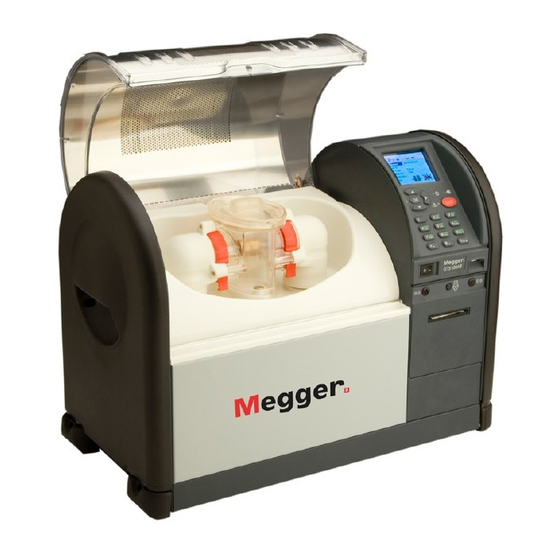
General Description The OTS60AF/2, OTS80AF/2 and OTS100AF/2 are transportable, easy to operate, oil test sets. A voltage selector fitted on the mains supply input panel at the rear permits the test sets to be operated from either 110 V, 120 V, 220 V or 240 V 50 Hz/60 Hz mains power supplies. The casing is made of sheet steel and carrying handles are fitted at each side. - Page 5 Cradle terminal Test chamber Sheet steel case H.V. transformer output terminal ‘horns’ Hinged Carrying handle polycarbonate cover Oil test vessel E.M.C./ Discharge barrier Control panel Internal printer Safety interlock on test chamber Figure 1. OTS100AF/2 oil test set layout (the OTS80AF/2 and OTS60AF/2 are similar). Liquid crystal display External printer...
-
Page 6: Applications
Applications The OTS60AF/2, OTS80AF/2 and OTS100AF/2 are used for determining the dielectric strength of liquid insulants, such as the insulating oils used in transformers, switchgear and other electrical apparatus. They are transportable and suitable for laboratory use as well as testing on site. A four wheeled trolley is available to assist with on-site transportation. -
Page 7: Specification
The test sets meet the requirements IEC 61010-1 E.M.C. In accordance with IEC 61326-1 Operational uncertainties Refer to www.megger.com Supply Voltage 220 V ± 10%, 240 V ± 10%, 110 V ± 10%, 120 V ± 10%, (four selectable values), 50 Hz / 60 Hz. -
Page 8: Accessories
Accessories Supplied with Instrument Part Number User Guide 6172-064 Mains power cord 25424-860 Oil test vessel fitted with spherical electrodes 12,7 mm diam. 6231-445 Oil test set preparation kit 6121-486 comprising:- two magnetic stirrers pair of cylindrical electrodes 1 inch diam. pair of mushroom electrodes 36 mm diam. - Page 9 Specification section). Glass fuses MUST NOT be used due to their low breaking capacity. Only test vessels manufactured and supplied by Megger Limited for use with the OTS60AF/2, OTS80AF/2 or OTS100AF/2 sets must be fitted within their respective test chambers.
-
Page 10: Preparing The Test Vessel
Operation Preparing the Test Vessel Separate the cover holding the electrode mountings from the container. Ensure that the vessel is thoroughly clean, both inside and out. Mount the appropriate electrodes on the sliding arms, if they are not already in place. It may be necessary to slacken one or both of the clamp screws at the base of the electrode supports and move the sliding arms back. -
Page 11: Loading The Test Vessel
EN60156 AS 1767 BS148 Standard BS 5874 CEI 10-1 test IEC 156 IP 295 ASTM D1816 ASTM D877 specification ΓOCT 6581 NFC 27 selected SABS 555 VDE 0370 UNE 21 STAS 286 Electrode shape Electrode 2,5 mm 2,54 mm 1 or 2 mm spacing Loading the Test Vessel Open the test chamber cover by turning the trapped key interlock knob a... -
Page 12: Preparing The Oil Test Set
Operation Preparing the Oil Test Set Adjust the mains voltage selector if necessary and connect the oil test set to a suitable supply. It is recommended that the green/yellow earth terminal is connected to a known good earth. Switch on both the supply and the test set. The copyright message appears on the display for a brief time and is followed by the main programme menu screen. - Page 13 Language Select The display screen and print-out can be set to read in any one of six languages:- ENGLISH FRANCAIS DEUTSCH ESPANOL PORTUGUES ITALIANO Scroll through and select as before. Pressing SELECT returns to the sub-menu. Note:- A quick way to bring the language screen into view on the screen is to press and hold the right hand key while switching the test set on.
-
Page 14: Automatic Testing Sequences
Operation When TIME / DATE is selected, a further sub menu is displayed as follows: DATE FORMAT VIEW QUIT SET DATE SET TIME Scroll through and select as before. DATE FORMAT offers the choice of U.K. date style (dd-mm-yy), or U.S. date style (mm/dd/yy). Successive pressing of the SELECT key will select the alternate style. -
Page 15: Minute Test
5 MINUTE TEST Note:- This is a non-standard test, designed to provide a rapid assessment of the oil condition. To commence the test, highlight 5 MINUTE TEST on the main menu and press select. The display will appear similar to figure 6. STIRRING: MAGNETIC 5 MINUTE TEST START... - Page 16 Operation When breakdown occurs (or if the maximum voltage is reached) the test voltage is cut off, the high voltage indicator light goes out and the test set begins its oil sample stirring period. The stirrer rotates for a period of 30 seconds and the breakdown voltage value of the previous test is retained on the display.
-
Page 17: As 1767, Bs 148, Bs 5874, Cei 10 -1, En60156, Iec 156, Ip 295, Nfc
Note:- At any time during a test sequence the right hand control key labelled STOP can be used to end a test and return to the test option display screen. Similarly during printing the left hand key labelled STOP can be used to stop the print function and return to the average breakdown display screen. -
Page 18: Astm D877 Test
Operation ASTM D877 test Note:- This specification does not require stirring. Do not fit a magnetic stirrer bar. To commence the test, highlight ASTM D877 on the main menu and press SELECT. The display will appear similar to figure 7. On pressing the START key, TEST 1 is initiated and the display appears similar to figure 7. - Page 19 Figure 12. Oil test vessel for ASTM D1816 specification. After the initial stand time is complete the high voltage is switched on and applied to the oilsample. The display appears similar to figure 8. The high voltage indicator light is illuminated, and the display shows the voltage rising at the rate of 0,5 kV/s being applied.
-
Page 20: Custom Test
Operation CUSTOM Test This option is included so that users can program their own test parameters. Custom test is therefore ideal for setting up other oil testing specifications. Up to five separate CUSTOM tests can be programmed, and once established are stored in memory for use on future occasions. Programming a CUSTOM test From the main menu select CUSTOM. -
Page 21: Withstand (Proof) Tests
If selected, the intermediate stir time between 0 seconds and 99 minutes 55 seconds may now be set on the display. Increment to the desired time using the left and centre keys and press SELECT. If selected, the intermediate STAND TIME between 0 seconds, and 99 minutes 55 seconds may now be set on the next display. - Page 22 Operation Initial stand time is displayed. Repeated pressing of the left hand key changes ENABLED: to YES or NO. To accept the displayed initial stand time, choose YES and press SELECT. To alter the displayed initial stand time, press the centre arrows key. The display then moves to a sub display to alter and set the initial stand time between 0 seconds and 99 minutes 55 seconds.Increment to the desired time using the left and centre keys, and press SELECT.
- Page 23 Withstand test ‘B’ Follow the procedure for Withstand test ‘A’, but note that after the test voltage has been maintained for 1 minute it will continue to rise at 2 kV/s to the breakdown point or to the maximum value, before it is automatically removed.
- Page 24 Operation On pressing the START key, the automatic test sequence is initiated, and the voltage is displayed ramping up to the withstand voltage level. Pressing the right hand key labelled STOP will abort the test, and return to the original display. On successfully attaining the upper voltage limit, the display will appear similar to figure 10.
-
Page 25: Self Check Tests
On completion of the test(s) (1, 2 or 3 may have been performed), the appropriate PASS or FAIL message is displayed. Pressing the right hand key labelled NEW returns to the EQUIPMENT CATEGORY selection display screen. Pressing the left hand key labelled VIEWchanges the top half of the display to list the breakdown voltage(s), together with the pass limit voltage. -
Page 26: Calibration Check
Operation Calibration Check The optional OTS/VCM100 calibrator provides the means to carry out a quick calibration check of the test set high voltage output. The calibrator fits onto the test chamber cradle terminals in place of a test vessel, and voltage indication is viewed on an analogue meter marked from 0 to 100kV in 2kV divisions (accuracy 3%).The scale also shows pass tolerance bands to enable a quick assessment of the accuracy to be made. -
Page 27: Printer Facilities
Printer Facilities Paper feed key The printer paper feed key, situated adjacent to the On/Off switch, may be pressed at any time (when the test set is switched on) to advance the paper roll. Replacing a printer paper roll Do not replace the printer paper roll while a test is being conducted. Remove the printer cover by releasing its two fasteners, by giving them each a 1/4 turn. -
Page 28: Downloading Results To A Pc
Operation Downloading Results to a PC To transfer test results to a PC, connect a suitable cable (see below) between the RS232 socket on the OTS and a serial port on the PC. A suitable communications program is required on the PC. When the OTS is set to print to an external printer, text will appear on the PC display, which may be copied to other programs for storage or calculation. -
Page 29: Print Out Information
Print Out Information Each print out provides all information related to the specific test carried out. Headings are also provided for insertion of sample identification and ambient temperature. Where a standard oil test specification allows different electrode shape and/or gap, these will be shown on the printout so that the user can indicate which were used. -
Page 30: Sampling And Testing Oil For Dielectric Strength
Sampling and Testing Oil for Dielectric Strength The following notes are mainly intended for the guidance of those whose experience in the subject may be limited. The notes should be read in conjunction with the relevant oil testing specifications. Causes of Bad Oil Transformers and switchgear oil may be rendered unsuitable for further use due to four main reasons:- Low dielectric strength. - Page 31 CONSIGNES DE SECURITE • Le boîtier d’essai d’huile doit être correctement mis à la masse. • La chambre d’essai doit être conservée scrupuleusement propre. • Le boîtier d’essai ne doit pas être utilisé si le couvercle de la chambre d’essai est fissuré ou endommagé d’une manière quelconque, auquel cas il doit être renvoyé...
- Page 32 N’EMPLOYEZ PAS de fusibles en verre étant donné que leur capacité de rupture est faible. Sur les appareils d’essai OTS60AF/2, OTS8OAF/2 et OTS100AF/2 utilisez uniquement les cuves d’essai fabriquées et fournies par Megger Limited et montez-les dans leur chambre respective d’essai.
- Page 33 Préparation de la cuve d’essai Séparez la cuve et le couvercle qui porte les supports des électrodes. Vérifiez que la cuve est d’une propreté absolue, à l’intérieur et à l’extérieur. Fixez les électrodes appropriées sur les bras coulissants si elles ne sont pas en place. Il vous faudra probablement desserrer une ou plusieurs vis de serrage au pied de ces supports pour repousser ces bras.
- Page 34 Fonctionnement EN60156 AS 1767 BS148 Spécifications BS 5874 CEI 10-1 sélectionées IEC 156 IP 295 ASTM D877 ASTM D1816 d’essai ΓOCT 6581 NFC 27 normalise SABS 555 VDE 0370 UNE 21 STAS 286 Profit des électrodes Ecartement 2,5 mm 2,54 mm 1 or 2 mm des électrodes Chargement de la cuve d’essai...
- Page 35 terre sur une masse jaune de qualité. Mettez sous tension l’alimentation secteur et l’appareil d’essai. Le message de droits d’auteur (copyright) apparaît brièvement à l’écran puis est remplacé par l’écran du menu principal de programmation. Ce menu offre les options suivantes: AS 1767-1976 ASTM D877 ASTM D1816-84a...
- Page 36 Fonctionnement touche centrale et de la touche gauche pour mettre en circuit ou hors circuit, en fonction de vos besoins, le contre-éclairage de l’affichage. Appuyez sur CHOIX pour revenir au sous-menu OPTIONS. Sélection de la langue Vous pouvez programmer l’écran d’affichage et les impressions sur l’une des six langues suivantes: ENGLlSH FRANCAIS DEUTSCH...
- Page 37 appuyez sur CHOIX. Pour revenir au menu principal, à partir du sous-menu OPTIONS, faites défiler la liste pour mettre en valeur l’option MENU puis appuyez sur CHOIX. HEURE/DATE L’heure et la date correctes sont programmées en usine et, normalement, vous n’avez pas besoin d’effectuer d’ajustement.
- Page 38 Fonctionnement ESSAI DE 5 MINUTES Remarque: cet essai n’est pas standard et a pour but de vérifier rapidement les caractéristiques de l’huile. Pour commencer cet essai, mettez en valeur l’option ESSAI 5 MINUTES sur le menu principal puis appuyez sur CHOIX. L’écran de la Figure 29 apparaît alors. AGITATION: AIMANT ESSAI 5 MINUTE DEPART...
- Page 39 Lorsqu’un fractionnement se produit (ou lorsque la tension maximale est atteinte), la tension d’essai est coupée, le témoin haute tension s’éteint et l’appareil d’essai commence sa phase d’agitation de l’échantillon d’huile. L’agitateur tourne pendant 30 secondes et la tension de fractionnement de l’essai principal reste à...
- Page 40 Fonctionnement pour revenir au menu principal. Remarque: à tout moment, pendant le déroulement d’une séquence d’essais, vous pouvez appuyer sur la touche de commande droite ARRET pour mettre fin à un essai et revenir à l’écran d’affichage des options d’essais. De même, pendant une impression, vous pouvez appuyez sur la touche gauche ARRET pour mettre fin à...
- Page 41 Essai ASTM D877 Remarque: cette spécification n’a pas besoin d’agitation. Par conséquent, ne montez pas une barre magnétique d’agitation. Pour commencer cet essai, mettez en valeur l’option ASTM D877 sur le menu principal puis appuyez sur CHOIX. Une pression sur la touche DEPART enclenche l’ESSAI i et l’écran de la Figure 30 apparaît. Cet écran indique que le temps de repos initial de 2 minutes 20 secondes a été...
- Page 42 Fonctionnement Figure 35. Cuve d’essai d’huile pour la spécification ASTM D1816 Cet écran affiche le mode d’agitation sélectionné et indique que le temps de repos initial de 3 minutes a été enclenché. Le temps restant initial vient s’inscrire en minutes et secondes. Dès que le temps de repos initial s’est écoulé, la tension d’essai élevée est automatiquement mise en circuit et est envoyée à...
- Page 43 Programmation d’un essai de PERSONNALISATION Sur le menu principal, sélectionnez l’option ESSAI OPERATEUR. ESSAI OPERATEUR 1 N. DES ESSAI VITESSE MONTEE 2:0 TEMPS AGITATION 0:30 TEMP REPOS 0:45 CHOIX SUIVANT PROG Figure 36. Ecran d’affichage de l’ESSAI OPERATEUR Les trois touches de commande assurent les fonctions: SUIVANT, CHOIX et MENU. Une pression sur la touche SUIVANT vous permet de passer à...
- Page 44 Fonctionnement Si vous avez sélectionné un temps d’agitation intermédiaire, vous pouvez maintenant programmer à l’écran une durée comprise entre 0 seconde et 99 minutes 55 secondes. Utilisez la touche gauche et la touche centrale pour faire apparaître la durée souhaitée puis appuyez sur CHOIX. Si vous avez sélectionné...
- Page 45 Le temps de repos initial vient s’afficher. Lorsque vous appuyez à plusieurs reprises sur la touche gauche, vous faites passer l’option POSSIBLE: de OUI à NON et ainsi de suite. Pour accepter le temps de repos initial à l’écran, choisissez OUI puis appuyez sur CHOIX. Pour modifier le temps de repos initial à l’écran, appuyez sur la touche centrale à...
- Page 46 Fonctionnement Essai de tenue “B” Procédez comme indiqué pour l’essai de tenue “A”. Cependant, nous vous signalons qu’après que la tension d’essai se soit maintenue pendant une minute, elle continue de monter au rythme de 2 kV/s jusqu’au point de fractionnement ou jusqu’à la valeur maximale, avant d’être automatiquement retirée. Essai BS5730a En vous référant à...
- Page 47 Une pression sur la touche DEPART déclenche la séquence d’essais automatique et la tension affichée s’élève jusqu’à la valeur de tenue. Une pression sur la touche droite ARRET met fin à cet essai et ramène l’écran d’origine. Dès que la limite supérieure de tension est atteinte, l’écran de la Figure 32 apparaît.
- Page 48 Fonctionnement Si ce troisième essai donne des résultats satisfaisants, l’écran de la Figure 43 apparaît. Si ce troisième essai échoue, l’écran de la Figure 44 apparaît et aucun test supplémentaire n’a lieu. Une fois ces essais réalisés (il peut yen avoir 1, 2 ou 3), le message BON ou DEFAUT apparaît. Une pression sur la touche droite NOUVEAU vous ramène à...
- Page 49 Avant que l’écran ne revienne automatiquement au menu principal, un essai portant sur la minuterie CHIEN DE GARDE se déroule. Ce MINUTEUR CHIEN DE GARDE a pour but de vérifier que le microprocesseur fonctionne de manière constante. Vérification de l’étalonnage Le dispositif de calibrage en option OTS/VCM1OO vous permet de vérifier rapidement l’étalonnage de la sortie haute tension de cet appareil d’essai.
- Page 50 Fonctionnement Dispositifs d’impression Touche d’avance du papier Cette touche se trouve à côté de l’interrupteur Marche/Arrêt. Vous pouvez appuyer à tout moment sur cette touche (lorsque l’appareil d’essai est sous tension) pour faire avancer le rouleau de papier. Remplacement du rouleau de papier Ne remplacez pas le rouleau de papier pendant le déroulement d’un essai.
- Page 51 Cette page est intentionnellment vierge...
- Page 52 Operation Informations communiquées par une impression Chaque impression fournit des informations portant sur l’essai spécifique réalisé. Les entêtes sont également prévues pour l’insertion de l’identification d’un échantillon et pour indiquer la température ambiante. Lorsqu’une norme d’essai d’huile permet d’utiliser des électrodes à profil différent et/ou à écartement différent, ces indications apparaissent sur l’impression papier afin de vous permettre, en tant qu’opérateur, d’identifier les électrodes employées.
- Page 53 Echantillonnage et essai de résistance diélectrique des huiles Les notes suivantes sont destinées principalement aux personnes ayant des connaissances limitées du sujet. Ces notes doivent être lues conjointement aux spécifications d’essai d’huile appropriées. Causes des mauvaises huiles L’huile de transformateur et d’appareillage de commutation peut être devenir inutilisable à cause de quatre raisons : Faible résistance diélectrique Forte acidité...
- Page 54 Operation Sicherheitswarnung • Das Ölprüfgerät muß ordnungsgemäß geerdet werden. • Die Prüfkammer ist absolut sauber zu halten. • Wenn die Abdeckung der Prüfkammer in irgendeiner Weise gerissen oder beschädigt ist, darf das Prüfgerät nicht verwendet werden, sondern ist zur Reparatur an eine autorisierte Vertretung zu senden.
- Page 55 Jegliche Ersatzsicherungen müssen dieser Spezifikation entsprechen (für ausführliche Einzelheiten vgl. den Abschnitt Spezifikationen). Glassicherungen DÜRFEN aufgrund ihrer Trägheit NICHT verwendet werden. Innerhalb der betreffenden Testkammern dürfen nur von Megger Limited zur Verwendung mit den Testgeräten OTS6OAF/2, OTS8OAF/2 oder OTS1OOAF/S gefertigte und gelieferte Behälter verwendet werden.
- Page 56 Vorbereitung des Testbehälters Trennen Sie die Abdeckung, welche die Elektrodenhalterungen hält, vom Behälter. Gewährleisten Sie, daß der Behälter innen und außen absolut sauber ist. Montieren Sie die jeweils passenden Elektroden, falls diese noch nicht installiert sind, an den Führungsarmen. Unter Umständen muß die eine oder andere Klemmschraube am Sockel der Elektroden halterung gelöst werden, damit der betreffende Führungsarm zurückgeschwenkt werden kann.
- Page 57 EN60156 AS 1767 BS148 Standard BS 5874 CEI 10-1 test IEC 156 IP 295 spezifikation ASTM D1816 ASTM D877 ΓOCT 6581 NFC 27 ausgewählt SABS 555 VDE 0370 UNE 21 STAS 286 Elektroden- Form Elektroden 2,5 mm 2,54 mm 1 or 2 mm Abstand Einsetzen des Testbehälters Drehen Sie zum Öffnen der Testkammer die Schlüsselverriegelung um eine Vierteidrehung...
- Page 58 Vorbereitung des Öltestgeräts Stellen Sie je nach Bedarf den Netzspannungswähler ein, und schließen Sie das Öltestgerät an eine geeignete Netzspannung an. Die gelbgrüne Erdungsklemme sollte mit einer bekanntermaßen guten Erdungsleitung verbunden werden. Schalten Sie sowohl die Netzspannung als auch das Testgerät ein. Daraufhin erscheint auf dem Bildschirm für kurze Zeit das Urheberechtssymbol und anschließend das Menü...
- Page 59 Betriebsanleitung Hintergrundbeleuchtung Wenn HINTERGRUNDBELEUCHTUNG gewählt worden ist, können Sie mit der mittleren und der linken Taste je nach Bedarf die Hintergrundbeleuchtung ein- oder ausschalten. Durch Drücken von WÄHLEN kehren Sie zum Untermenü OPTIONEN zurück. Sprachenauswahl Der Bildschirm und die Ausdrucke können auf folgende sechs Sprachen eingestellt werden: ENGLISH FRANÇAIS DEUTSCH...
- Page 60 Zwecks Rückkehr zum Untermenü OPTIONEN heben Sie STOP hervor und drücken dann WÖHLEN. Zwecks Verlassen des Untermenüs OPTIONEN und Rückkehr zum Hauptmenü heben Sie MENÜ hervor und drücken dann WAHLEN. UHRZEIT/DATUM Uhrzeit und Datum sind voreingestellt und brauchen normalerweise nicht justiert zu werden. Die interne 24-Stundenuhr wird von einer Lithiumbatterie mit einer Lebensdauer von 10 Jahren betrieben.
- Page 61 Betriebsanleitung 5-MINUTEN-TEST Hinweis: Dies ist kein Standardtest, sondern wurde auf die schnelle Bestimmung des Ölzustands ausgelegt. Heben Sie zum Starten des Tests im Hauptmenü die Option 5-MINUTEN-TEST hervor, und drücken Sie dann WÄHLEN. Daraufhin erscheint eine Anzeige wie in Abbildung 52. RÜHREN: MAGNETIC 5-MINUTEN-TEST START...
- Page 62 Wenn Durchschlag eintritt (oder die Höchstspannung erreicht wird), wird die Testspannung abgeschaltet, die Hochspannungsanzeigeleuchte verlischt, und das Testgerät beginnt mit dem Rühren. Das Rührwerk arbeitet 30 Sekunden lang, und der Wert der Durchschlagsspannung des vorherigen Tests bleibt angezeigt. Die Anzeige sieht wie in Abbildung 55 aus: XX kV 00:30 TEST 1...
- Page 63 Betriebsanleitung Drücken Sie zur Rückkehr zum 5-MINUTEN-TEST die Taste NEU und anschließend die linke Taste START zur Wiederholung einer Testfolge oder die Taste MENU zur Rückkehr zum Hauptmenü. Hinweis: Zu jedem Zeitpunkt während einer Testfolge kann die Taste STOP zur Unterbrechung des Tests und zur Rückkehr zur Anzeige der Testoptionen gedrückt werden.
- Page 64 Test ASTM D877 Hinweis: Diese Spezifikation erfordert kein Rühren. Montieren Sie keinen Magnetrührstab. Wählen Sie für den Beginn des Tests im Hauptmenü die Option ASTM D877, und drücken Sie anschließend die Taste WÄHLEN Die Anzeige erscheint wie in Abbildung 52 dargestellt. Nach dem Drücken der Taste START wird TEST 1 eingeleitet, und die Anzeige erscheint wie in Abbildung 53 dargestellt.
- Page 65 Betriebsanleitung Abbildung 58: Öltestbehälter für Spezifikation ASTMD 1816 Die Anzeige meldet das gewählte Rührverfahren und das Ablaufen der Anfangszeit von 3 Minuten. Die verbleibende Zeit wird in Minuten und Sekunden angezeigt. Wenn die Anfangszeit abgelaufen ist, wird die Hochspannung eingeschaltet und angelegt. Die Anzeige erscheint wie in Abbildung 54 dargestellt.
- Page 66 Programmieren von CUSTOM-Tests Wählen Sie CUSTOM aus dem Hauptmenü. Die Anzeige erscheint wie in Abbildung 59 dargestellt. TEST KONFIG. 1 ANZAHL DER TESTS ANSTIEGRATE RÜHRWERK EINSCH 0:30 RÜHRZEIT 0:45 NÄCHST WÄHLEN MENÜ Abbildung 59: Anzeige für CUSTOM-Test Die drei Steuertasten haben die Funktionen NÄCHST, WÄHLEN und MENÜ. Durch Drücken der Taste NÄCHST rücken Sie zum nächsten (der fünf verfügbaren) CUSTOM- Tests vor.
- Page 67 Betriebsanleitung Wenn Zwischenrührzeit gewählt ist, kann ein zwischenzeitlicher Betrieb des Rührwerks von 0 Sekunden bis 99 Minuten, 55 Sekunden eingestellt werden. Stellen Sie durch Drücken der linken und der mittleren Taste den gewünschten Wert ein, und drücken Sie dann WÄHLEN. Wenn Zwischenstandzeit gewählt ist, kann eine zwischenzeitliche Unterbrechung des Rührbetriebs von 0 Sekunden bis 99 Minuten, 55 Sekunden eingestellt werden.
- Page 68 Daraufhin ändert sich die Anzeige und zeigt die Höhe der Stehspannung an, die nun wie gewünscht geändert werden kann - vgl. Abbildung 60. Steigern oder verringern Sie mit der linken und der mittleren Taste die Spannung auf den gewünschten Wert. Hinweis: Wiederholtes Drücken einer Taste ändert den jeweiligen Wert in Abständen von 1 kV.
- Page 69 Betriebsanleitung Stehspannungstest “B” Verfahren Sie zunächst wie bei Stehspannungstest “A”, doch beachten Sie, daß die Stehspannung nach einer Minute mit einer Rate von 2 kV/s weiter bis zum Durchschlag bzw. bis zum Grenzwert ansteigt, bevor sie automatisch abgeschaltet wird. BS5730a-Test Für den Test BS5730a muß...
- Page 70 Mit der Taste START wird die Testfolge automatisch eingeleitet, und das Ansteigen der Stehspannung bis zum Grenzwert wird angezeigt. Mit der rechten, durch STOP gekennzeich- neten Taste kann der Test abgebrochen und die ursprüngliche Anzeige aufgerufen werden. Wenn der obere Grenzwert der Spannung erfolgreich erreicht worden ist, erscheint eine Anzeige wie in Abbildung 56 dargestellt.
- Page 71 Betriebsanleitung Wenn der dritte Test erfolgreich war, erscheint die Anzeige wie in Abbildung 65 dargestellt. Ein nicht erfolgreicher Test bewirkt eine Anzeige wie in Abbildung 66 dargestellt, und weitere Tests werden nicht durchgeführt. Nach Abschluß des oder der Tests (1, 2 oder 3) wird die entsprechende Mitteilung GUT oder FEHLER angezeigt.
- Page 72 Bevor die Anzeige automatisch zum Hauptmenü zurückkehrt, wird eine Prüfung der ZEITÜBERWACHUNG (WATCHDOG TIMER) durchgeführt, die dafür sorgt, daß der Mikroprozessor kontinuierlich arbeitet. Kalibrierungsprüfung Die als Option lieferbare OTS/VCM100-Kalibrierung ermöglicht eine schnelle Überprüfung der Kalibrierung des Hochspannungsausgangs des Testgeräts. Das Kalibriergerät wird anstelle eines Testbehälters auf die Aufnahmebügel des Testbehälters aufgesetzt und auf einem Analog-Meßinstrument dann die Spannungsstärke in Stufen von 2 kV (mit einer Genauigkeit von ±...
- Page 73 Betriebsanleitung Druckereinrichtungen Taste für Papierzuführung Die Taste für das Druckerpapier befindet sich neben dem Ein-/Ausschalter und kann (bei eingeschaltetem Drucker) jederzeit zum Vorschub des Papiers verwendet werden. Auswechseln einer Papierrolle Wechseln Sie die Papierrolle nicht während der Durchführung eines Tests. Entfernen Sie die Druckerabdeckung durch Lösen der beiden Halterungen, indem Sie sie um eine Viertelumdrehung drehen.
- Page 74 Diese Siete wurde absichtlich unedruckt gelassen...
- Page 75 Ausdrucken von Informationen Jeder einzelne Ausdruck enthält sämtliche Informationen bezüglich eines jeweils durchgeführten Tests. Außerdem werden Überschriften für die Eintragung von Musterkenzeichnung und Umgebungstemperatur eingefügt. Soweit eine Standard-Öltest-Spezifikation unterschiedliche Elektrodenformen und Elektroden- abstände zuläßt, werden diese ebenfalls auf dem Ausdruck vermerkt, so daß der Anwender feststellen kann, welche Formen und Abstände verwendet wurden.
- Page 76 Entnahme von Ölproben und Prüfung der Durchschlagsfestigkeit des Öls Die folgenden Hinweise richten sich in erster Linie an Bediener, die mit der Materie noch nicht vollkommen vertraut sind, und sollten zusammen mit den entsprechenden technischen Daten zur Ölprüfung gelesen werden. Unbrauchbares Öl und seine Ursachen Es gibt vier hauptsächliche Ursachen, aus denen das Öl von Transformatoren und Schaltvorrichtungen unbrauchbar werden kann...
- Page 77 Avisos de Seguridad • El conjunto de prueba de aceite debe estar conectado a tierra correctamente. • La cámara de prueba debe mantenerse escrupulosamente limpia. • Si la tapa de la cámara de prueba está agrietada o dañada en modo alguno, el conjunto de prueba no debe ser usado, sino que deberá...
- Page 78 DEBEN utilizarse fusibles de vidrio debido a que tienen un poder de ruptura muy bajo. Sólo los recipientes de prueba fabricados y suministrados por Megger Limited para uso con los equipos OTS60AF/2, OTS80AF/2 ó OTS100AF/2, deben instalarse en sus respectivas cámaras de prueba.
- Page 79 Cómo preparar el recipiente de prueba Separe la cubierta que aguanta los soportes de electrodos del contenedor. Asegúrese de que el recipiente esté completamente limpio, tanto dentro como fuera. Monte los electrodos adecuados en los brazos móviles, si todavía no se encuentran en lugar. Es posible que se tenga que aflojar uno o ambos tornillos de fijación en la base de los soportes de electrodos y mueva los brazos móviles de nuevo a su posición anterior.
- Page 80 Funcionamiento EN60156 AS 1767 BS148 Especificación BS 5874 CEI 10-1 de prueba IEC 156 IP 295 ASTM D877 ASTM D1816 estánder ΓOCT 6581 NFC 27 seleccionada SABS 555 VDE 0370 UNE 21 STAS 286 Forma de electrodo Espaciado de 2,5 mm 2,54 mm 1 or 2 mm electrodo...
- Page 81 Cómo preparar el equipo de prueba de aceite Ajuste el selector de tensión de alimentación si es necesario y conecte el equipo de prueba de aceite a una alimentación adecuada. Se recomienda la conexión del terminal a tierra verde/amarillo a una buena toma de tierra conocida.
- Page 82 Funcionamiento Iluminación de visualización Cuando se seleccione ILUMINACION DE VISUALIZACION, podrán utilizarse las teclas izquierda y central para “Conectar” o “Desconectar” la iluminación de visualización, según proceda. Pulse ESCOGER para regresar al submenú de OPCIONES. Selección de idioma La pantalla de visualización e impresión pueden ajustarse de manera que aparezcan en cualquiera de los seis idiomas siguientes: ENGLISH FRANCAIS...
- Page 83 Para volver al submenú de OPCIONES, desplácese por la pantalla hasta que se destaque SALIR, luego pulse ESCOGER. Para volver al menú principal desde el submenú de OPCIONES, desplácese por el mismo hasta que se destaque MENU y pulse ESCOGER. HORA / FECHA La hora y fecha correctas están preajustadas y por lo general no necesitarán ajustarse.
- Page 84 Funcionamiento PRUEBA DE 5 MINUTOS Nota: Se trata de una prueba no estándar, diseñada para facilitar una evaluación rápida de la condición del aceite. Para empezar la prueba, destaque PRUEBA DE 5 MINUTOS en el menú principal y pulse escoger. La pantalla será parecida a la figura 74. AGITACION: POR IMAN PRUEBA DE 5 MINUTOS INIC.
- Page 85 Cuando tiene lugar la ruptura (o se alcanza la tensión máxima), se corta la tensión de la prueba, se apaga el piloto indicador de alta tensión y el equipo de prueba empieza su período de agitación de la muestra de aceite. El agitador girar durante un período de 30 segundos y el valor de tensión de ruptura de la prueba anterior se sigue reteniendo en la pantalla.
- Page 86 Funcionamiento Pulse la tecla NUEVO para regresar al inicio de la prueba de 5 MINUTOS, seguido de la tecla izquierda INICIAR para repetir una secuencia de prueba, o la tecla MENU para regresar al menú principal. Nota: En cualquier momento durante una secuencia de prueba, la tecla de control derecha etiquetada PARE puede utilizarse para detener una prueba y volver a la pantalla de visualización de la opción de prueba.
- Page 87 Prueba ASTM D877 Nota: Esta especificación no requiere agitación. No instale una barra agitadora por imán. Para empezar, destaque ASTM D87 en el menú principal y pulse escoger. La pantalla será parecida a la figura 74. Al pulsar la tecla INICIAR, se inicializa la PRUEBA 1 y la pantalla aparecerá de forma similar a la figura 75.
- Page 88 Funcionamiento Figura 80. Recipiente de prueba de aceite para la especificación ASTM D1816. La visualización indica el modo de agitación seleccionado y que está teniendo lugar el lapso de espera inicial de 3 minutos. El lapso de espera inicial restante aparece en minutos y segundos. Después haberse completado el lapso inicial de espera, la alta tensión se conectará...
- Page 89 Cómo programar una prueba ESPECIAL Seleccione ESPECIAL en el menú principal. La pantalla seráparecida a la figura 81. PRUEBA ESPECIAL 1 NUMERO DE PRUEBAS AUMENTO kV/SEC. AGITACION CONTINUA 0:30 TIEMPO DE AGIT 0:45 ESCOGER PROX. MENÜ Figura 81. Pantalla de visualización de la prueba ESPECIAL. Estas tres teclas de control tienen las funciones PROX., ESCOGER, MENU.
- Page 90 Funcionamiento De seleccionarse, ahora podrá ajustarse el tiempo de agitación intermedio entre O segundos y 99 minutos 55 segundos. Aumente al tiempo deseado utilizando las teclas izquierda y central y pulsando ESCOGER. De seleccionarse, ahora podrá ajustarse el LAPSO intermedio entre O segundos y 99 minutos 55 segundos en la siguiente pantalla.
- Page 91 Se visualiza el lapso inicial de espera. La pulsación repetida de la tecla izquierda cambia UTILIZAR: a SI o NO. Para aceptar el lapso inicial de espera visualizado, escoja SI y luego pulse ESCOGER. Para alterar el lapso inicial de espera, pulse las teclas de flecha centrales. Entonces la pantalla pasaráa una subpantalla para alterar y ajustar el lapso inicial de espera entre 0 segundos y 99 minutos 55 segundos.
- Page 92 Funcionamiento Prueba de veriticación “B” Siga el procedimiento para la prueba de verificación “B”, pero tenga en cuenta que después de haberse mantenido la tensión de prueba durante 1 minuto, seguiráaumentando a 2 kV/s hasta el punto de ruptura o hasta el valor máximo antes de eliminarse automáticamente. Prueba BS5730 Con referencia a BS 573Oa, ajuste y regule el espacio de electrodo adecuado de 2,5 mm ó...
- Page 93 Al pulsar la tecla INICIAR, se inicia la secuencia de prueba automática y se visualiza la tensión ascendiendo al nivel de tensión de verificación. Pulsando la tecla derecha etiquetada PARE se abortará la prueba y regresaráa la pantalla original. Si se consigue alcanzar el límite de tensión superior, la pantalla será...
- Page 94 Funcionamiento Si se pasa la tercera prueba, la pantalla será parecida a la figura 9Oa. Si no se pasa la tercera prueba, apareceráuna pantalla parecida a la figura 90b, y no se realizarán más pruebas. Al terminarse la(s) prueba(s) (es posible que se hayan realizado 1, 2 ó 3 pruebas), se visualizará...
- Page 95 Antes de que la pantalla regrese automáticamente al menú principal, se efectuará una CONTROLACION DE SECUENCIA. El SINCRONIZADOR DEL CONTROLADOR DE SECUENCIA asegura que el microprocesador esté constantemente funcionando. Comprobación de calibración Este calibrador opcional OTS/VCM100 facilita los medios necesarios para realizar una rápida comprobación de calibración de la salida de alta tensión del equipo de prueba.
- Page 96 Funcionamiento Funciones de la impresora Tecla de alimentación de papel La tecla de alimentación de papel para la impresora, situada junta al interruptor de Con/Descon, podrápulsarse en cualquier momento (cuando el equipo de prueba esté conectado) para avanzar el rollo de papel.
- Page 97 Esta págine se deja en blanco a propósito...
- Page 98 Operation Información de impresión Cada impresión facilita toda la ¡nformación relacionada con la prueba específica realizada. También se facilitan encabezamientos para la inserción de identificación de muestra y temperatura ambiente. Cuando la especificación estándar de prueba de aceite permite diferentes formas y/o espacios de electrodos, estas dos opciones aparecerán en la impresión de manera que el usuario pueda indicar cuáles son las que se usaron.
- Page 99 Muestreo del aceite y prueba de su resistencia dieléctrica Las notas siguientes se ofrecen principalmente a modo de guía para aquellos cuya experiencia en el tema puede ser limitada. Las notas deberán leerse en conjunción con las especificaciones de prueba de aceite pertinentes.
-
Page 100: Repair And Warranty
Approved Repair Companies A number of independent instrument repair companies have been approved for repair work on most Megger equipments, using genuine Megger spare parts. Consult the Appointed Distributor / Agent regarding spare parts, repair facilities and advice on the best course of action to take. - Page 102 Operation...
- Page 104 T 1 30.16.08.90 F 1 34.61.28.77 This instrument is manufactured in the United Kingdom. The company reserves the right to change the specification or design without prior notice. Megger is a registered trademark Part No. 6171-064 V15 Printed in England 1108 www.megger.com...
Need help?
Do you have a question about the OTS 60AF/2 and is the answer not in the manual?
Questions and answers