
Summary of Contents for Astor Astraada SRV-63 series
- Page 1 Operation Manual Astraada SRV-63 AC Servo drives - 1 - The owner of Astraada brand is ASTOR Sp. z o.o.
- Page 2 SRV-63 series AC servo drives Preface Preface Thanks for selecting SRV-63 servo drives. SRV-63 servo drive series products adopt modular design with abundant functions and powerful performance. The upper PC software uses USB communication and the bus control is optional among Modbus bus, CANopen bus, EtherCAT bus, MotionNet bus and the PROFIBUS-DP bus which can be selected via extension card.
-
Page 3: Safety Precautions
SRV-63 series AC servo drives Safety precautions Safety precautions Safety icons: Following safety precautions should be paid attention to before any installation, configuration, operation, maintenance and inspection: Check whether the AC power supply is the same as the rated voltage of the servo drive, otherwise fire, hurt, damage to the drive may occur. - Page 4 SRV-63 series AC servo drives Safety precautions Do not touch the heat sink and external braking resistor during operation, otherwise burning may occur for the hot sides. Do install the overcurrent protector, leakage current protector and emergency device and ensure the normal usage after wiring, otherwise electric shock, hurt and fire may occur.
-
Page 5: Table Of Contents
SRV-63 series AC servo drives Product overview Content Preface ............................I Safety precautions ......................... II Content ............................4 Chapter 1 Product overview ......................6 1.1 Servo drive ........................... 6 1.2 Servo motor ........................12 1.3 Cables ..........................13 Chapter 2 Installation instruction ....................16 2.1 Drive dimension ........................ - Page 6 SRV-63 series AC servo drives Product overview 6.2 Autotuning control parameters (P1) ..................99 6.3 Motor control parameters (P2) ................... 105 6.4 I/O management parameters (P3) ..................115 6.5 Extension and application (P4) ..................131 6.6 Program JOG, homing and PTP control (P5) ..............147 6.7 Application function (P6) ....................
-
Page 7: Chapter 1 Product Overview
SRV-63 series AC servo drives Product overview Chapter 1 Product overview 1.1 Servo drive 1.1.1 Instruction to the drive SRV-63 series servo drive (200W~5.5kW) Specification Description 230V system input voltage 1P/3P AC220V(-15%)~240V(+10%) 47Hz~63Hz Power supply 400V system input voltage 3P AC380V(-15%)~440V(+10%) 47Hz~63Hz 10 inputs for standard type, pulse type and CANopen bus type;... - Page 8 SRV-63 series AC servo drives Product overview SRV-63 series servo drive (200W~5.5kW) Specification Description 1. Retention pulse clearing; 2. Command pulse input disabled; Control input 3. Electronic gear ratio switching; 4. Vibration control switching, etc Control output Positioning completion output, etc Max.
- Page 9 SRV-63 series AC servo drives Product overview SRV-63 series servo drive (200W~5.5kW) Specification Description clamp the speed mode and position mode Speed command A delay filter of analog input speed command filter Speed command Zero drift control against outside interference with zero drift control 0.3mV precision Control input...
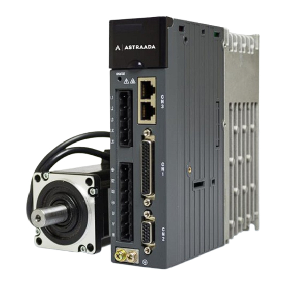
- Page 10 SRV-63 series AC servo drives Product overview 1.1.2 External appearance of the drive Standard model S1: STO sele ction CN 5:2nd e ncode r a nd S TO CN 4:US B port of up per P C LED dis play CH AR GE light Operation pane l Pow er su pply of main circ uit...
- Page 11 SRV-63 series AC servo drives Product overview 1.1.3 Naming of the drive AS63SRV 2 0C2 - S Description Astraada SRV-63 series Input voltage 2: 230VAC; 4: 400VAC Power ratings: C05: 50W 0C4: 400W 0C7: 750W 1C0: 1.0kW 2C0: 2.0kW 5C5: 5.5kW Machine type S: Standard;...
- Page 12 SRV-63 series AC servo drives Product overview 1.1.4 Name plate of the drive 1.1.5 Power ratings and cabinet volumes Input Output Cabinet Model Rated current Power Rated volume Voltage (V) (kW) current (A) AS63SRV20C2 Single/Three phase 220 1.8/0.8 Single/Three phase 220 3.6/1.5 AS63SRV20C4 Single/Three phase 220...
-
Page 13: Servo Motor
SRV-63 series AC servo drives Product overview 1.2 Servo motor 1.2.1 Nameplate of the motor “2300” on the name plate is the motor model, and please input the number into P0.00 correctly Note: (P0.00 is long parameter which can be set via keypad. See details at chapter 5.2.1 (8), otherwise, the servo system may not operate normally and major fault may occur to the drive and motor. -
Page 14: Cables
SRV-63 series AC servo drives Product overview 1.3 Cables 1.3.1 Nameplate of cables 1.3.2 Naming of the power cables AS63 CBL 07 03 - A Description Example Manufacturer Product Astraada SRV-63 Power cable Power cable CBL - Power cable 07 - 0.75mm 10 - 1.0mm Coil diameter Coil diameter... - Page 15 SRV-63 series AC servo drives Product overview 1.3.3 Naming of the encoder cables AS63 CBE 06 03 - A D Description Example Manufacturer Product Astraada SRV-63 Encoder cable Encoder cable CBE - Encoder cable 06 - 6 - core cable Cable core Core 09 - 9 - core cable...
- Page 16 SRV-63 series AC servo drives Product overview 1.4 Braking resistor specification Embedded braking Min. resistance of external Drive model resistor braking resistors 60Ω AS63SRV20C2 60Ω AS63SRV20C4 30Ω 60W 30Ω AS63SRV20C7 30Ω 60W 30Ω AS63SRV21C0 60Ω 60W 60Ω AS63SRV41C5 60Ω 60W 40Ω...
-
Page 17: Chapter 2 Installation Instruction
SRV-63 series AC servo drives Installation instruction Chapter 2 Installation instruction 2.1 Drive dimension 2.1.1 A/B/C volume and dimension diagram 2.1.2 D volume and dimension diagram External dimension Installation dimension Installation Volume Model H(mm) W(mm) D(mm) A (mm) B1 (mm) B2 (mm) W1(mm) hole (mm) AS63SRV20C2 22.5... -
Page 18: Drive Installation
SRV-63 series AC servo drives Installation instruction 2.2 Drive installation 2.2.1 Installation mode 1) Base installation (there is a Φ5 installation hole at the lower left corner and upper right corner of the rear board respectively) 2) Bracket installation (the installation bracket is optional) Partition bracket L1 C L2 C... - Page 19 SRV-63 series AC servo drives Installation instruction 2.2.2 Installation space and direction Please install the servo drive vertically and keep enough installation space for good ventilation. Install fans if necessary to ensure the temperature inside the control cabinet is lower than 45℃. 1) Single drive installation >100mm >100mm...
-
Page 20: Motor Dimension
SRV-63 series AC servo drives Installation instruction 2.3 Motor dimension Note: As motor structure and dimension may vary slightly with design modification, for those who are sensitive to the installation length of motor, please confirm the installation length with our business staff before ordering. - Page 21 SRV-63 series AC servo drives Installation instruction 2.3.2 Motor dimensions with 130 base (mm) Flange dimensions Main dimensions Model L3 L4 H1 H2 L2 L6 P H AH D1 B WK HK LK HS LS AS63MTR21C0-A 110(h7) 6 12 145 9 45 165 130 22(h6) 55 6h9 7 41 18 45 143 99 68 123 83 114.5 AS63MTR42C0-A 110(h7) 6...
-
Page 22: Motor Installation
SRV-63 series AC servo drives Installation instruction 2.3.3 Motor dimensions with 180 base (mm) Dimensions Model HK B AS63MTR43C0-A 114.3(h7) 232 35(h7) 10(h9) 38 180.5 233 13.5 138.5 AS63MTR44C4-A 114.3(h7) 262 35(h7) 10(h9) 38 180.5 233 13.5 138.5 AS63MTR45C5-A 114.3(h7) 292 35(h7) 10(h9) 38 180.5 233... -
Page 23: Technical Parameters Of Servo Motor
SRV-63 series AC servo drives Installation instruction Note: Please ensure the motor code of the name plate is the same as P0.00 before using for the best performance. The motor code is shown as below: the last 4 figures are the motor code 2.5 Technical parameters of servo motor ASTRAADA SRV PARAMETERS AS63MTR20C2-A... - Page 24 SRV-63 series AC servo drives Installation instruction AS63MTR41C5-I AS63MTR42C0-A AS63MTR43C0-A AS63MTR44C4-A AS63MTR45C5-A AS63MTB41C5-I AS63MTR42C0-I AS63MTR43C0-I AS63MTR44C4-I AS63MTR45C5-I Model AS63MTB42C0-A AS63MTB43C0-A AS63MTB44C4-A AS63MTB45C5-A AS63MTB42C0-I AS63MTB43C0-I AS63MTB44C4-I AS63MTB45C5-I Rated Power 1.5 kW 2 kW 3 kW 4.4 kW 5.5 kW Rated torque 7.7 Nm 9.55 Nm 19 Nm...
-
Page 25: Chapter 3 Wiring Instruction
SRV-63 series AC servo drives Wiring instruction Chapter 3 Wiring instruction 3.1 System wiring Power L1 L2 L3 Breaker Use d to cu t o ff th e circu it wh e n p o w e r ca b le flo w s th ro u g h o ve rcu rre n t Noise filter Pre ve n t th e n oise o u tsid e... - Page 26 SRV-63 series AC servo drives Wiring instruction 3.1.1 Requirements on input power cable The dimension of input power cable shall comply with local regulations. The input power cable must be able to withstand corresponding load current. The max rated temperature margin of input power cable should not be lower than 70℃ under continuous operation.
- Page 27 SRV-63 series AC servo drives Wiring instruction 3.1.3 Cable diameter of main circuit Recommended cable Connectable cable Terminal Tightening diameter (mm diameter (mm Drive model screw torque L1\L2\L3 L1\L2\L3 (+), B2, specification (Nm) L1C\L2C B3, (-) AS63SRV20C2 AS63SRV20C4 0.75 0.75 0.75 0.75~4 0.75~4 0.75~4...
-
Page 28: Terminal Wiring Of The Main Circuit
SRV-63 series AC servo drives Wiring instruction 3.2 Terminal wiring of the main circuit 3.2.1 Wiring diagram of single phase 230V · The user is required to make this emergency stop protection circuit. · Add surge absorbing devices on both ends of the electromagnetic contactor winding. - Page 29 SRV-63 series AC servo drives Wiring instruction 3.2.2 Wiring diagram of three phase 230V/400V · The user is required to make this emergency stop protection circuit. · Add surge absorbing devices on both ends of the electromagnetic contactor winding. · Input voltage range of 220V system: Breaker AC 220V(-15%)~240V(+10%)
-
Page 30: Wiring Of Motor Power Cables
SRV-63 series AC servo drives Wiring instruction 3.3 Wiring of motor power cables 3.3.1 2500-PPR 60, 80-base 200W~750W motor power cable A direction view Wiring relation Definition Core wire color X1.7 X2.3 Brown X1.6 X2.1 X1.5 X2.2 Blue Ground terminal X2.4 Yellow/green X1.4... -
Page 31: Control I/O-Cn1 Terminal Layout
SRV-63 series AC servo drives Wiring instruction Definition Core wire color X1.7 X2.4 Brown X1.6 X2.3 X1.5 X2.2 Blue Ground terminal X2.1 Yellow/green X1.4 X1.3 Short connect with X1.2 X1.2 Short connect with X1.3 X1.1 3.3.4 130, 180-base 2kW~4.4kW (230V) and 4.4kW~5.5kW (400V) motor power cable Brown Blue A direction view... -
Page 32: Wiring Of Encoder-Cn2 Terminals
SRV-63 series AC servo drives Wiring instruction 3.5 Wiring of encoder-CN2 terminals 3.5.1 CN2 terminals CN2 terminal function Name Function Remark V+/ SD+ Parallel encoder V+/Serial encoder data+ Signal of parallel encoder W+ Signal of parallel encoder A+ Signal of parallel encoder A- Encoder power supply Signal of parallel encoder U+ Different... - Page 33 SRV-63 series AC servo drives Wiring instruction X1.14 X2.14 X1.5 X2.5 Twisted pair X1.12 X2.12 Steel casing Steel casing 3.5.3 130, 180-base absolute value encoder cable A dire ction v iew B dire ction v iew Wiring relation Signal Core wire structure X1.1 X2.11 Twisted pair...
-
Page 34: Wiring Of 485/Can-Cn3 Terminals
SRV-63 series AC servo drives Wiring instruction 3.5.5 130, 180-base incremental encoder cable A dir ec tion v iew B dire ction v iew Wiring relation Signal Core wire structure X1.1 X2.2 Twisted pair X1.7 X2.3 X1.5 X2.4 Twisted pair X1.12 X2.5 VB-5V... -
Page 35: Wiring Of Usb-Cn4 Terminals
SRV-63 series AC servo drives Wiring instruction 3.7 Wiring of USB-CN4 terminals Pin1 Pin5 CN4 USB port function Remark Name Functions Data - Data + The standard cable for USB micro to USB-A conversion is available. Signal ground 1, 4 Unused 3.8 Encoder and STO-CN5 terminal wiring 3.8.1 Terminal interface and definition... -
Page 36: Wiring Of Profibus-Dp Terminals
SRV-63 series AC servo drives Wiring instruction CN5 port function Name Function Remark EXZ- Linear encoder (2 encoder) Z- EXZ+ Linear encoder (2 encoder) Z+ Unused 3.9 Wiring of PROFIBUS-DP terminals DP plug pin layout GND_BUS B_Line A_Line +5V_BUS DP plug signal layout DP terminal function Remark Name... -
Page 37: Chapter 4 Control Mode Applications
SRV-63 series AC servo drives Control mode applications Chapter 4 Control mode applications 4.1 Standard wiring of the position mode -36-... -
Page 38: Standard Wiring Of The Speed Mode
SRV-63 series AC servo drives Control mode applications 4.2 Standard wiring of the speed mode -37-... -
Page 39: Standard Wiring Of The Torque Mode
SRV-63 series AC servo drives Control mode applications 4.3 Standard wiring of the torque mode -38-... -
Page 40: Cn1 Function Instruction
SRV-63 series AC servo drives Control mode applications 4.4 CN1 function instruction 4.4.1 Pins of CN1 terminal CN1 plug pin layout DO6 COM- DO3 DO5 GND GND GND DI7 COM+ OCB DO4 + DI10 PULS PULS OCA GND DI5 SIGN- SIGN+ OCS CN1 plug signal layout 4.4.2 Definition of CN1 terminals Sign... - Page 41 SRV-63 series AC servo drives Control mode applications 4.4.3 Power supply signal Sign Pin no. Name Function COM- is the ground terminal of the 24V power. Its capacity is Internal 24V 100mA. If the actual load is higher than this value, the user power supply shall provide the power supply by themselves.
- Page 42 SRV-63 series AC servo drives Control mode applications Position/fully-closed loop mode Speed mode Symbol Name Default Function Default Function Mark Mark value name value name Retention Speed Digital input 9 0x007 0x00E S-SIGN pulse clearing command sign Command DI10 22 Digital input 10 0x008 0x006 Gain switching...
- Page 43 SRV-63 series AC servo drives Control mode applications Torque mode MotionNet mode Symbol Name Default Function Default Function Mark Mark value name value name Servo ready 15 Digital output 2 0x003 Fault output 0x001 output Torque 11 Digital output 3 0x010 TRCH 0x003...
- Page 44 SRV-63 series AC servo drives Control mode applications Signal name Sign Function number Available mode Gain switching 0x06 This function is the control signal of 1 and 2 gain switching. Signal name Sign Function number Available mode Retention pulse clearing 0x07 This function is the control signal of retention pulse clearing and the detailed operation is relative to the setting of P3.45.
- Page 45 SRV-63 series AC servo drives Control mode applications Signal name Sign Function number Available mode Zero speed clamp 0x0D This function serves as the control signal of zero speed clamp and please refer to P0.58 for detailed information. Signal name Sign Function number Available mode Speed command sign...
- Page 46 SRV-63 series AC servo drives Control mode applications PtP2.53[126 position] PtP2.55[127 position] Signal name Sign Function number Available mode External fault 0x14 This function is the signal of external input fault alarm. If the digital input is valid, the drive will report Er10-3 and stop. Signal name Sign Function number Available mode...
- Page 47 SRV-63 series AC servo drives Control mode applications Signal name Sign Function number Available mode PTP control trigger TRIG 0x1B In the PTP control mode, it needs to be used with internal position command 1~4. During using, select the target step by the internal position command selection 1~4, and then trigger the switching action selected by target step via the rising edging of this digital value.
- Page 48 SRV-63 series AC servo drives Control mode applications Signal name Sign Function number Available mode JOG function of the terminal DJOG 0x2C When this digital input is valid, JOG function of the terminal is valid. Signal name Sign Function number Available mode Gantry synchronization input clear 0x2D...
- Page 49 SRV-63 series AC servo drives Control mode applications The function is the state signal when the drive displays the fault alarm. When it is valid, the drive has fault. Signal name Sign Function number Available mode External brake release signal 0x05 The function is the control release signal of output motor brake.
- Page 50 SRV-63 series AC servo drives Control mode applications The function is the state signal of whether there is speed command or not. When it is valid, non-zero speed command controls the motors. Signal name Sign Function number Available mode Speed zero output 0x0D The function is the state signal of whether the current speed feedback is 0.
- Page 51 SRV-63 series AC servo drives Control mode applications This function is output PTP output 5 signal. Signal name Sign Function number Available mode PTP output 6 PTPO6 0x1C This function is output PTP output 6 signal. Signal name Sign Function number Available mode PTP output 7 PTPO7 0x1D...
-
Page 52: Cn1 Wiring Instruction
SRV-63 series AC servo drives Control mode applications 4.4.7 Encoder output signals and functions Sign Pin no. Name Function Output the frequency divided encoder signal, comply with A phase output the standard of TIA/EIA-422-B. The output phase A pulse and phase B pulse is still B phase output quadrature. - Page 53 SRV-63 series AC servo drives Control mode applications Connection diagram when the local power supply is used: 40 24V 40 24V 2 COM+ 2 COM+ 16 DI1 16 DI1 12 COM- 12 COM- Drive side Drive side 40 24V 40 24V 2 COM+ 2 COM+ 16 DI1...
- Page 54 SRV-63 series AC servo drives Control mode applications Connection mode 2: Open collector mode 1 The control module is NPN (common cathode) Shielded Twisted cable pair PULS PULS- SIGN SIGN- DC24V Control module side Drive side The control module is PNP module (common anode): DC24V Twisted Shielded...
- Page 55 SRV-63 series AC servo drives Control mode applications The control module is PNP (common anode): DC12~24V Shielded Twisted cable pair 23 PULS+ PULS 24 PULS- 32 SIGN+ SIGN 33 SIGN- Control module side Drive side The input pulse frequency is 200kHz; if the local 24V power supply (it only can provide 100mA current) or the 12~24V power supply provided by the user is used, it is required to connect to current-limiting resistor R(the resistance is selected as the below table).
- Page 56 SRV-63 series AC servo drives Control mode applications 4.5.4 Wiring of digital output circuit Connection diagram when the power supply is provided by user: Users must install this Users must connect to current Drive side Drive side freewheeling diode when limit resistor when connecting connecting to inductive load to optical coupler...
- Page 57 SRV-63 series AC servo drives Control mode applications 4.5.5 Wiring of frequency division output circuit of encoder feedback signal Differential mode: AM26LS32 Shielded Twisted Terminal or equivalent chip cable pair resistor OA+ 44 OB+ 41 OZ+ 28 GND 5 Connect to shielded cable according to Drive side device requirement...
- Page 58 SRV-63 series AC servo drives Control mode applications 4.5.6 Wiring of the analog output circuit Measuring instruments or Servo drive external circuit Shield cable Twisted pair GND 5 GND 5 Connect the shield cable according to the requirement There are two analog output circuits in all. The output voltage range is -10V~10V. The Max output current is 3mA.
-
Page 59: Cn5 Wiring Diagram
SRV-63 series AC servo drives Control mode applications 4.6 CN5 wiring diagram encoder and STO ① Safety terminal signal is active-high ① Safety output signal is active-high EDM+ HWBB1+ HWBB1- EDM- HWBB2+ S1:STO switch HWBB2- WheN S1 set To ON, sAfetY input termiNal signaL is ②... - Page 60 SRV-63 series AC servo drives Control mode applications Control module is PNP type (common anode): DC24V - Shielded cable Twisted pair OC_EXA EXA- OC_EXB EXB- OC_EXZ EXZ- Control module side Drive side Max input pulse frequency is 200kHz; if the local 24V power of SRV-63 (only 100mA power is available) or the 24V power provided by the user is used, there is no need to connect current limit resistor.
- Page 61 SRV-63 series AC servo drives Control mode applications Control mode is PNP type (common cathode): DC12~24V Shielded Twisted cable pair EXA+ EXA- EXB+ EXB- EXZ+ EXZ- Control module side Drive side Max input pulse frequency is 200kHz; if the local 24V power of SRV-63 (only 100mA power is available) or the 24V power provided by the user is used, it is required to connect to current limit resistor R.
-
Page 62: Chapter 5 Running And Operation
SRV-63 series AC servo drives Running and operation Chapter 5 Running and operation 5.1 Running 5.1.1 First powering on Please check following items before power on: 1) Wiring The power supply of the servo drive (L1, L2, L3, L1C, L2C or R, S and T) should be connect with proper techniques;... - Page 63 SRV-63 series AC servo drives Running and operation 5.1.1.2 Checking after powering-on After switching on both of the control circuit and main circuit power supplies, if the power supply is OK, the LED indicator will display 0 first and then display 8. If there is no fault alarm of the servo drive, the LED on the front panel displays the current speed of the servo motor as default.
- Page 64 SRV-63 series AC servo drives Running and operation Steps: Complete the connection between the drive and the servo motor. Set P0.03 to “0”, the position control mode. Confirm the pulse output of the upper controller and adjust P0.23. Keep the pulse type the same with that of the upper controller.
- Page 65 SRV-63 series AC servo drives Running and operation 5.1.5 Running at the torque control mode Simple connection: Servo drive 12~24V Parameter Function Setting value COM+ P0.03 Mode selection Torque command … P0.60 … selection … … Torque command Set according to …...
- Page 66 SRV-63 series AC servo drives Running and operation Hereunder only some necessary parameters are listed: 1) Mode setting The control mode (position mode, speed mode, torque mode, fully-closed loop mode or other compound control mode) can be set through setting parameter P0.03 according to the control requirements on the site.
- Page 67 SRV-63 series AC servo drives Running and operation motor when an alarm occurs through setting parameter P4.30. See description of P4.30 for details. This process will not cause regenerative braking. When the digital input terminal configured as zero speed clamp (ZRS) is set to ON and P0.58 is at non-zero value, the servo motor stops running.
- Page 68 SRV-63 series AC servo drives Running and operation 5.1.9 Sequence diagram 5.1.9.1 Sequence diagram of power-on and servo ON Power-on process Servo On process Main power Main circuit power-on Control power Control circuit power-on About 1.2s Microprocessor state Program initialization Program starts running Note 1 Servo ready state...
- Page 69 SRV-63 series AC servo drives Running and operation 5.1.9.2 Sequence diagram of power loss during running Main power Main circuit power loss Note 1 Control circuit power disconnection Control power PWM output Servo has output Servo has no output Servo ready output Valid Invalid (RDY)
- Page 70 SRV-63 series AC servo drives Running and operation 5.1.9.4 Servo OFF sequence in running state Servo enabling (SON) Enable Disabled Servo fault output No fault alarm (ALM) Servo ready output Valid (RDY) Dynamic brake Dynamic brake state Note 1 Dynamic brake switches on switches off PWM output Servo has output...
-
Page 71: Display And Operation
SRV-63 series AC servo drives Running and operation 5.2 Display and operation 5.2.1 Display Keypad diagram: USB port Display MODE key SET/SHIFT key UP key DOWN key LED display character (reference table): Corresponding Corresponding Corresponding Corresponding display display display display symbol symbol symbol... - Page 72 SRV-63 series AC servo drives Running and operation Button function table: Function MODE Used to switch between different modes or return to previous menu Used to select parameter upwards or increase value DOWN Used to select parameter downwards or decrease value Press for a long time =SET (about 0.6 seconds) Used to select parameter downwards or decrease value SET/SHIFT...
- Page 73 SRV-63 series AC servo drives Running and operation 8. Setting of long parameters (corresponds to parameters with over 6 digits) in parameter area: MODE SHIFT MODE DOWN SHIFT SHIFT DOWN SHIFT SHIFT SHIFT DOWN DOWN 5.2.2 State monitoring mode After power on, the screen will enter into “General monitoring mode”, display the parameters name for about 2.5 seconds and then display the current value.
- Page 74 SRV-63 series AC servo drives Running and operation the displaying interface. If no operation in R3 menu interface, it will return to the monitoring interface in 20 seconds. If no operation in R0 and R1 menu interface, it will stay on the displaying interface. Operation flowchart: DOWN DOWN...
- Page 75 SRV-63 series AC servo drives Running and operation Sign Name Jogging test Restore the factory parameter Program commissioning Analog input 1 zero drift clear Analog input 2 zero drift clear Analog input 3 zero drift clear Inertia identification Absolute value encoder clear Note: The auxiliary functions can be operated only when servo is disabled, otherwise users cannot enter the auxiliary function menu.
- Page 76 SRV-63 series AC servo drives Running and operation 5.2.5.4 Operation flowchart of program commissioning Press MODE key to the auxiliary function mode. Press UP/DOWN key to the menu, and press SET key to the interface. The interface will display . In the interface of SHIFT key can be used to switch between , start and stop the commissioning function.
- Page 77 SRV-63 series AC servo drives Running and operation 5.2.5.6 Operation flowchart of absolute encoder clear If the multi-turn encoders are used, the zeroing of mechanical system is needed after first power on. Press MODE key to switch to the auxiliary function mode. Press UP/DOWN key to the menu, and press SET key to the interface.
-
Page 78: Chapter 6 Detailed Parameter Description
SRV-63 series AC servo drives Detailed parameter description Chapter 6 Detailed parameter description P-position mode; S-speed mode; T-torque mode;F- fully-closed loop mode. The definition of direction: From the angle of facing motor shaft, the counterclockwise direction is forward (CCW for short); clockwise (CW) is reverse; in terms of speed and torque reference value, positive value means position direction and negative value means negative direction. - Page 79 SRV-63 series AC servo drives Detailed parameter description 1~12 Generally, the system will set this parameter automatically after P0.00 is set correctly. In cases where encoder disconnection fault is reported during power up when motor is connected correctly, please check whether the drive supports motor encoder type, refer to chapter 1.1.3. The naming of servo motor contains encoder type, refer to chapter 1.2.2.
- Page 80 SRV-63 series AC servo drives Detailed parameter description Setting working working Instruction value mode mode Position mode: Control the angular displacement of servo motor via internal/external position command, thus achieving controlling over mechanical motion displacement. Speed mode: Control the rotation speed of the servo motor with the internal or external speed command Torque mode: Control the torque of the servo motor with the internal or external torque command.
- Page 81 SRV-63 series AC servo drives Detailed parameter description Speed mode Torque mode Speed mode Mode switching signal (MCH) Motor speed Load torque Torque command Note: The switching mode is not limited by actual operation. Fully-closed loop mode: Use the linear encoder to detect the devices of control object and conduct information feedback position control.
- Page 82 SRV-63 series AC servo drives Detailed parameter description Data size 16bit Data format P0.04* Modbus address 1008,1009 CANopen address 0x2004, 0x00 Setting range Default Unit Available mode P0.05 JOG speed 0~1000 r/min This parameter can be used to set the jog speed. For jogging, please refer to chapter 5.2.5.2 During jogging, the ACC/DEC time parameters (P0.54, P0.56, P0.55, and P0.57) are active.
- Page 83 SRV-63 series AC servo drives Detailed parameter description Setting value Logic of B phase A phase A phase Non-reverse B phase B phase A phase A phase Reverse B phase B phase Data size 16bit Data format P0.08 Modbus address 1016,1017 CANopen address 0x2008, 0x00...
- Page 84 SRV-63 series AC servo drives Detailed parameter description Data size 16bit Data format P0.09 Modbus address 1018,1019 CANopen address 0x2009, 0x00 Setting range Default Unit Available mode P0.10 Max torque limit 1 0.0~500.0 300.0 Setting range Default Unit Available mode P0.11 Max torque limit 2 0.0~500.0...
- Page 85 SRV-63 series AC servo drives Detailed parameter description This parameter is used to set the parameters which can be monitored while powering-on of the system: Setting value Parameter meaning Sign Unit Motor rotation speed r/min Speed command r/min reference unit Pulse feedback accumulation reference unit Pulse command accumulation...
- Page 86 SRV-63 series AC servo drives Detailed parameter description Data size 16bit Data format P0.16 Modbus address 1032,1033 CANopen address 0x2010, 0x00 Setting range Default Unit Available mode P0.17 EEPROM write mode This parameter is used to set the EEPROM write mode Setting value Command pulse input Saved one by one (automatic saved after modification)
- Page 87 SRV-63 series AC servo drives Detailed parameter description This parameter is used to set the manner of pulse input. There are 3 types of pulse input manners: Shown in the picture Setting Pulse input Signal form value form Pulse + mode Pulse+Sign FWD/REV CW+CCW pulse mode...
- Page 88 SRV-63 series AC servo drives Detailed parameter description Concept of the electronic gears: for any pulse input, the number and frequency of the pulse actually received by the drive can be changed by multiplying a certain coefficient and this coefficient is electronic gear ratio. It can be indicated in two parts: numerator and denominator: Electronic gear ratio = g1 Of which g1: The numerator of the electronic gear ratio;...
- Page 89 SRV-63 series AC servo drives Detailed parameter description Data size 32bit Data format P0.25 Modbus address 1050,1051 CANopen address 0x2019, 0x00 Data size 32bit Data format P0.26 Modbus address 1052,1053 CANopen address 0x201A, 0x00 Data size 32bit Data format P0.27 Modbus address 1054,1055 CANopen address...
- Page 90 SRV-63 series AC servo drives Detailed parameter description Note: If the parameter is modified during the operation, it will be valid after stopping. Data size 16bit Data format P0.34 Modbus address 1068,1069 CANopen address 0x2022, 0x00 Setting range Default Unit Available mode Software limit of forward P0.35...
- Page 91 SRV-63 series AC servo drives Detailed parameter description P0.49 Internal speed 4 P0.50 Internal speed 5 P0.51 Internal speed 6 P0.52 Internal speed 7 P0.53 Internal speed 8 Please refer to the detailed instruction of P0.46~P0.53. The motor speed can be controlled by applying -10V~10V voltage between analog speed input terminals (AD1, GND, pin “1”...
- Page 92 SRV-63 series AC servo drives Detailed parameter description 2. The voltage of the analog speed command input corresponds to the changing gain of the motor command speed. 3. The relation between analog speed command input voltage and the speed, the default value is that each 1V corresponds to 100r/min.
- Page 93 SRV-63 series AC servo drives Detailed parameter description Setting range Default Unit Available mode P0.46 Internal speed 1/Speed limit 1 -20000~20000 r/min Setting range Default Unit Available mode P0.47 Internal speed 2/Speed limit 2 -20000~20000 r/min Setting range Default Unit Available mode P0.48 Internal speed 3/Speed limit 3...
- Page 94 SRV-63 series AC servo drives Detailed parameter description Data size 16bit Data format P0.48 Modbus address 1096,1097 CANopen address 0x2030, 0x00 Data size 16bit Data format P0.49 Modbus address 1098,1099 CANopen address 0x2031, 0x00 Data size 16bit Data format P0.50 Modbus address 1100,1101 CANopen address...
- Page 95 SRV-63 series AC servo drives Detailed parameter description Setting range Default Unit Available mode P0.56 ACC time of S curve 0~1000 Setting range Default Unit Available mode P0.57 DEC time of S curve 0~1000 In a case of reference speed command, this parameter is used to set the duration of the circular arc segment during S curve decelerating and thus to achieve the goal of smooth starting.
- Page 96 SRV-63 series AC servo drives Detailed parameter description 2. In the torque mode, mode 0 and 1 are valid, mode 2 and 3 are the same with mode 1. Data size 16bit Data format P0.58 Modbus address 1116,1117 CANopen address 0x203A, 0x00 Setting range Default...
- Page 97 SRV-63 series AC servo drives Detailed parameter description Data size 16bit Data format P0.61 Modbus address 1122,1123 CANopen address 0x203D, 0x00 Setting range Default Unit Available mode P0.62 Analog input 2 gain 0~2000 (0.1%)/V Suppose the analog input 2 function selection is torque command: Parameter instruction: 1.
- Page 98 SRV-63 series AC servo drives Detailed parameter description The analog input 2 function selection is torque command by default: If the absolute value of analog torque command voltage is in this range, the corresponding torque value is 0. Data size 16bit Data format P0.65...
- Page 99 SRV-63 series AC servo drives Detailed parameter description Data size 16bit Data format P0.69 Modbus address 1138,1139 CANopen address 0x2045, 0x00 Setting range Default Unit Available mode Absolute encoder mode P0.70 setting This parameter is used to modify the operation mode of the multi-turn absolute encoder. When the matching encoder for the motor is multi-turn absolute encoder, it will be taken as single-turn encoder by default;...
-
Page 100: Autotuning Control Parameters (P1)
SRV-63 series AC servo drives Detailed parameter description the parameter and the unit is the unit of the encoder pulse. 2. When it is set to -1 and switches from speed mode to position mode, there is no positioning action and it will switch at the current position. 3. - Page 101 SRV-63 series AC servo drives Detailed parameter description Setting range Default Unit Available mode P1.02 inertia ratio 0~10000 The definition is the same as P1.01. Note: The automatic online gain adjustment is invalid for this parameter. Data size 16bit Data format P1.02 Modbus address 1204,1205...
- Page 102 SRV-63 series AC servo drives Detailed parameter description This parameter is used to set the operation mode of inertia identification. Setting value Function Forward rotation and then reverse rotation Forward rotation Reverse rotation Reverse rotation and then forward rotation Data size 16bit Data format P1.05...
- Page 103 SRV-63 series AC servo drives Detailed parameter description Note: When the set value of P1.19 is increasing, the sensitivity to the resonance is reducing. Data size 16bit Data format P1.19 Modbus address 1238,1239 CANopen address 0x2113,0x00 Setting range Default Unit Available mode Resonance detection P1.20...
- Page 104 SRV-63 series AC servo drives Detailed parameter description 2. This function is only for read and cannot be set. The user can set the frequency of notch filter according to the function code to remove the mechanical resonance. 3. 5000 indicates the resonance point is not found. Data size 16bit Data format...
- Page 105 SRV-63 series AC servo drives Detailed parameter description Data size 16bit Data format P1.27 Modbus address 1254,1255 CANopen address 0x211B,0x00 Data size 16bit Data format P1.28 Modbus address 1256,1257 CANopen address 0x211C,0x00 Setting range Default Unit Available mode P1.29 notch filter frequency 50~5000 5000 Setting range...
-
Page 106: Motor Control Parameters (P2)
SRV-63 series AC servo drives Detailed parameter description with 0x11C or 0x01C (VS-SEL). Relation with COM-: 0:OFF (the internal optical coupler corresponding to the input is not conducted); 1:ON (the internal optical coupler corresponding to the input is conducted). Data size 16bit Data format P1.35... - Page 107 SRV-63 series AC servo drives Detailed parameter description Setting range Default Unit Available mode speed integral time P2.01 constant 0.1~1000.0 21.0 This parameter is used to set the integral time constant of the speed loop. Decreasing the setting value may improve the response, but it may easily cause vibration and noise. It should be noted particularly that when this parameter is set to 1000, it means the integral action is invalid.
- Page 108 SRV-63 series AC servo drives Detailed parameter description There are two groups of parameters respectively for position gain, speed gain and speed integral time constant, speed detection filter and torque filter. The definition of the function and content are the same with those of 1 group.
- Page 109 SRV-63 series AC servo drives Detailed parameter description Setting range Default Unit Available mode Torque feed-forward filter P2.13 time 0.00~64.00 0.00 This parameter is used to set the torque feed-forward filter time. Data size 16bit Data format P2.13 Modbus address 1426,1427 CANopen address 0x220D,0x00...
- Page 110 SRV-63 series AC servo drives Detailed parameter description Setting Switching Gain condition value condition gain fixed Be fixed in 1 gain [P2.00~P2.04] gain fixed Be fixed in 2 gain [P2.05~P2.09] Switching Invalid: 1 gain input with gain Valid: 2 gain In the previous 1 gain, if the absolute value of torque command exceed Large torque...
- Page 111 SRV-63 series AC servo drives Detailed parameter description Data size 16bit Data format P2.22 Modbus address 1444,1445 CANopen address 0x2216,0x00 Setting range Default Unit Available mode Delay time of position P2.23 control switching 0~10000 In the position control, if set P2.22 to 3~9, when switching from 2 gain to 1 gain, it is the time from meeting the trigger conditions to the actual switching.
- Page 112 SRV-63 series AC servo drives Detailed parameter description The trigger conditions of gain switching during speed control are as below: Setting Switching Gain condition value condition gain fixed Be fixed in 1 gain [P2.00~P2.04] gain fixed Be fixed in 2 gain [P2.05, P2.06, P2.08, P2.09] Switching input Invalid: 1...
- Page 113 SRV-63 series AC servo drives Detailed parameter description Setting range Default Unit Available mode Switching delay of P2.30 speed control 0~20000 Based on mode In the speed control, if set P2.27 to 3~5, it is necessary to set switching conditions. The unit will be vary with the mode and setting.
- Page 114 SRV-63 series AC servo drives Detailed parameter description Setting range Default Unit Available mode Switching delay of P2.34 torque control 0~20000 Based on mode In the torque control, if set P2.31 to 3, it is necessary to set switching conditions. The unit will vary with the switching mode and setting.
- Page 115 SRV-63 series AC servo drives Detailed parameter description Data size 16bit Data format P2.44 Modbus address 1488,1489 CANopen address 0x222C,0x00 Setting range Default Unit Available mode Fully-loop vibration suppressor P2.50 valid Set whether the speed detector is valid by this parameter Setting value Function Invalid...
-
Page 116: I/O Management Parameters (P3)
SRV-63 series AC servo drives Detailed parameter description Friction compensation Setting range Default Unit Available mode P2.70 max-speed 0~1000 r/min This parameter is used to set the max-speed of friction compensation. Data size 16bit Data format P2.70 Modbus address 1540,1541 CANopen address 0x2246,0x00 Positive torque coefficient... - Page 117 SRV-63 series AC servo drives Detailed parameter description Setting value Optical coupler Optical coupler Signal name Sign Available mode non-conduction conduction valid valid — Invalid 0x100 0x000 Positive direction drive disabled 0x101 0x001 Negative direction drive disabled 0x102 0x002 Servo enabling 0x103 0x003 Alarm clearing...
- Page 118 SRV-63 series AC servo drives Detailed parameter description (Reserved) 0x126 0x026 (Reserved) 0x127 0x027 (Reserved) 0x128 0x028 (Reserved) 0x129 0x029 (Reserved) 0x12A 0x02A Terminal JOG enabling DJOG 0x12C 0x02C Gantry synchronization input clear 0x12D 0x02D Master gantry synchronization 0x12E 0x02E alignment sensor Slave gantry synchronization 0x12F...
- Page 119 SRV-63 series AC servo drives Detailed parameter description Note: The default value is the function selection corresponds to position mode. Data size 16bit Data format P3.01 Modbus address 1602, 1603 CANopen address 0x2301, 0x00 Data size 16bit Data format P3.02 Modbus address 1604, 1605 CANopen address...
- Page 120 SRV-63 series AC servo drives Detailed parameter description Speed reaching 0x10A 0x00A Speed limiting 0x10B 0x00B Speed command or not SCMD 0x10C 0x00C Speed zero output 0x10D 0x00D Torque limiting 0x10E 0x00E Zeroing finished HEND 0x10F 0x00F Torque reaching TRCH 0x110 0x010 (Reserved)
- Page 121 SRV-63 series AC servo drives Detailed parameter description Data size 16bit Data format P3.12 Modbus address 1624, 1625 CANopen address 0x230C, 0x00 Data size 16bit Data format P3.13 Modbus address 1626, 1627 CANopen address 0x230D, 0x00 Data size 16bit Data format P3.14 Modbus address 1628, 1629...
- Page 122 SRV-63 series AC servo drives Detailed parameter description For example, after analog input 1 command terminal of the drive is connected with analog reference signal, then even if the analog reference signal is 0, the voltage value of analog input 1 (R1.05) displayed by the panel will be 0.02V, P3.20 should be set to 0.02 at this time.
- Page 123 SRV-63 series AC servo drives Detailed parameter description Data size 32bit Data format P3.23 Modbus address 1646,1647 CANopen address 0x2317,0x00 Setting range Default Unit Available mode P3.24 Filter of analog input 2 0.0~1000.0 This parameter is used to set the time constant of the first order low-pass filter corresponds to the command .
- Page 124 SRV-63 series AC servo drives Detailed parameter description Data size 16bit Data format P3.26 Modbus address 1652, 1653 CANopen address 0x231A, 0x00 Data size 16bit Data format P3.27 Modbus address 1654, 1655 CANopen address 0x231B, 0x00 Analog speed Setting range Default Unit Available mode...
- Page 125 SRV-63 series AC servo drives Detailed parameter description Analog input 3* ℃ Drive temperature Note: When P3.31, P3.33 is set to 1000, the analog speed command, analog torque command and analog input 3 outputs the voltage value inputted from the analog input terminal at any time. Data size 16bit Data format...
- Page 126 SRV-63 series AC servo drives Detailed parameter description This parameter can be used to adjust the AO1 and AO2 to regulate the actual value of analog output voltage. Actual value of analog output voltage = Original value of analog output voltage + Offset value of analog output voltage Data size 32bit...
- Page 127 SRV-63 series AC servo drives Detailed parameter description Setting value Function Emergency stop switch is normal Emergency stop switch is disabled If the digital input set as EMG is active, then Er10-4 will occur. Note: 1. If Er10-4 occurs, the servo drive will stop at the stopping mode set by P4.30. 2.
- Page 128 SRV-63 series AC servo drives Detailed parameter description position feedback pulse and position command pulse is in this range, it indicates position arrival. Data size 32bit Data format P3.50 Modbus address 1700,1701 CANopen address 0x2332,0x00 Setting range Default Unit Available mode Output mode of position P3.51 arrival...
- Page 129 SRV-63 series AC servo drives Detailed parameter description Valid → The critical value of invalid: (P3.53 + 10) r/min Data size 16bit Data format P3.53 Modbus address 1706,1707 CANopen address 0x2335,0x00 Setting range Default Unit Available mode P3.54 Speed reaching range 10~20000 1000 r/min...
- Page 130 SRV-63 series AC servo drives Detailed parameter description Data size 16bit Data format P3.58 Modbus address 1716,1717 CANopen address 0x233A,0x00 Setting range Default Unit Available mode P3.59 Torque reaching range 5.0~300.0 50.0 This parameter is used to set the detection condition for torque reaching output. If the motor torque feedback exceeds this setting value, the output of TRCH (0x010 of 0x110) is valid.
- Page 131 SRV-63 series AC servo drives Detailed parameter description Data size 16bit Data format P3.72 Modbus address 1744,1745 CANopen address 0x2348,0x00 Setting range Default Unit Available mode P3.73 Gain of analog input 3 0~2000 This parameter is used to set the gain of analog input 3. The units correspond to different function of P3.70 are listed below: P3.70 Setting value Definition...
-
Page 132: Extension And Application (P4)
SRV-63 series AC servo drives Detailed parameter description Setting range Default Unit Available mode Deadzone mode of analog P3.77 input Set the deadzone voltage mode of analog input by this parameter Setting value Definition Normal mode CNC mode. When AI is smaller than the deadzone, the valid value is 0: When AI is larger than the deadzone, the valid value is AI-deadzone. - Page 133 SRV-63 series AC servo drives Detailed parameter description This parameter is used to select CAN communication baud rate. Available baud rate are as follow: Setting value Baud rate 1000kbps 500kbps 250kbps 125kbps 50kbps 20kbps Data size 16bit Data format P4.02 Modbus address 1804,1805 CANopen address...
- Page 134 SRV-63 series AC servo drives Detailed parameter description 485 communication fault Setting range Default Unit Available mode P4.06 clearing mode Set the processing method of the drive during 485 communication fault. Setting value Meaning Do not clear fault Clear fault automatically Data size 16bit Data format...
- Page 135 SRV-63 series AC servo drives Detailed parameter description 6.5.2 Servo type and communication control command Setting range Default Unit Available mode P4.10 Upper PC type This parameter is used to set the upper PC type which is classified by the interface of upper PC control drive.
- Page 136 SRV-63 series AC servo drives Detailed parameter description Setting range Default Unit Available mode Switching command of P4.15* control mode When P4.10 is 1, this parameter can be used to switch the control mode in hybrid control mode. Setting value Function Actual control mode Position/speed...
- Page 137 SRV-63 series AC servo drives Detailed parameter description If P4.10 is 1, this parameter can be used to set the inertia ratio switching command. Setting value Function Actual inertia ratio Disabled The first inertia ratio (P1.01) Enabled The second inertia ratio (P1.02) Data size 16bit Data format...
- Page 138 SRV-63 series AC servo drives Detailed parameter description If P4.10 is 1, this parameter can be used to set the external fault command. Setting value Function Disabled Enabled Data size 16bit Data format P4.22* Modbus address 1844,1845 CANopen address 0x2416,0x00 Setting range Default Unit...
- Page 139 SRV-63 series AC servo drives Detailed parameter description the running speed is high with large inertia load, please use the dynamic brake with caution. Do not start the dynamic brake frequently; otherwise, damage may occur to the servo drive. Data size 16bit Data format P4.30...
- Page 140 SRV-63 series AC servo drives Detailed parameter description Setting range Default Unit Available mode Undervoltage protection of P4.36 main power supply This parameter is used to set whether the drive will report main circuit undervoltage alarm when undervoltage occurs to the main power supply. Setting value Protection Do not display the undervoltage fault of the main circuit (Er13-1)
- Page 141 SRV-63 series AC servo drives Detailed parameter description Setting range Default Unit Available mode Internal speed of high P4.42 resolution -20000.0~20000.0 r/min This parameter is used to set the internal speed of high resolution Data size 32bit Data format P4.42 Modbus address 1884, 1885 CANopen address...
- Page 142 SRV-63 series AC servo drives Detailed parameter description 6.5.4 Fully-closed loop control Setting range Default Unit Available mode Frequency division molecular of P4.60 external linear encoder linear encoder. When This parameter is used to set the frequency division molecular of external the setting value is 0, the encoder resolution is the frequency division molecular by default.
- Page 143 SRV-63 series AC servo drives Detailed parameter description Setting range Default Unit Available mode External grating pulse P4.67 output mode of AB phase In fully-closed loop mode, this parameter is used to set the signal source of pulse feedback output. Setting value Pulse feedback signal source Encoder feedback...
- Page 144 SRV-63 series AC servo drives Detailed parameter description Setting range Default Unit Available mode P4.78 MotionNet node number 0~63 Set communication node number of local machine (slave station) in MotionNet communication. Data size 16bit Data format P4.78 Modbus address 1956, 1957 CANopen address 0x244E, 0x00 Setting range...
- Page 145 SRV-63 series AC servo drives Detailed parameter description communication (4012 corresponds to R0.04). Data size 16bit Data format P4.83 Modbus address 1966,1967 CANopen address 0x2453,0x00 Setting range Default Unit Available mode Configuration of PZD P4.84 feedback parameter 2 4000~5852 4018 This parameter is used to set the mapping content of feedback parameter 2 in PROFIBUS-DP communication (4018 corresponds to R0.07).
- Page 146 SRV-63 series AC servo drives Detailed parameter description Setting range Default Unit Available mode P4.88 CANopen heartbeat cycle 0~32767 1000 CANopen heartbeat cycle of the salve station. Data size 16bit Data format P4.88 Modbus address 1976,1977 CANopen address 0x2458,0x00 Automatic stop at CANopen Setting range Default Unit...
- Page 147 SRV-63 series AC servo drives Detailed parameter description Setting range Default Unit Available mode P4.92* Restore to factory value After this operation, all parameters (P0~P6 group) can be restored to the default value. Setting value Function Disabled Enabled Data size 16bit Data format P4.92*...
-
Page 148: Program Jog, Homing And Ptp Control (P5)
SRV-63 series AC servo drives Detailed parameter description Setting range Default Unit Available mode EEPROM operation of P4.97* communication encoder All the motor parameters can be written into the EEPROM and during the starting, the drive will initialize the data of the relative parameters. Data size 16bit Data format... - Page 149 SRV-63 series AC servo drives Detailed parameter description (waiting time P5.04→forward moving P5.01→waiting time P5.04→reverse moving P5.01) × cycle time P5.05 P5.05 P5.02 P5.01 Speed 0 P5.01 P5.04 P5.03 P5.04 P5.02 (waiting time P5.04→reverse moving P5.01→waiting time P5.04→forward moving P5.01) × cycle time P5.05 P5.05 P5.02 P5.01...
- Page 150 SRV-63 series AC servo drives Detailed parameter description time or the time from the finishing of one displacement to the starting of next displacement. Data size 16bit Data format P5.04 Modbus address 2008,2009 CANopen address 0x2504,0x00 Setting range Default Unit Available mode P5.05 JOG cycle times...
- Page 151 SRV-63 series AC servo drives Detailed parameter description Data size 16bit Data format P5.10 Modbus address 2020,2021 CANopen address 0x2505,0x00 Setting range Default Unit Available mode Homing automatically P5.11 after power on This parameter is used to set whether it can return to home automatically after power on. Setting value Instruction Invalid...
- Page 152 SRV-63 series AC servo drives Detailed parameter description Data size 16bit Data format P5.15* Modbus address 2030,2031 CANopen address 0x250F,0x00 Setting range Default Unit Available mode P5.16 Correlated action of homing Set the correlated action of homing via this parameter Setting value Function No action...
- Page 153 SRV-63 series AC servo drives Detailed parameter description Signal Function [-1] Invalid Control 0-127 step, equivalent to digital input: TRIG + POSn 0-127 function. 128-2047 Invalid 2048 Forced to stop Example: Writing PTP signal 3 means to trigger the PTP program 3. Data size 16bit Data format...
- Page 154 SRV-63 series AC servo drives Detailed parameter description Setting range Default Unit Available mode P5.36 15 target speed 0~6000 3000 r/min These parameters are used to set the target speed of each step bit. Data size 16bit Data format P5.21 Modbus address 2042,2043 CANopen address...
- Page 155 SRV-63 series AC servo drives Detailed parameter description Setting range Default Unit Available mode P5.39 02 ACC/DEC time 0~32767 Setting range Default Unit Available mode P5.40 03 ACC/DEC time 0~32767 Setting range Default Unit Available mode P5.41 04 ACC/DEC time 0~32767 Setting range Default...
- Page 156 SRV-63 series AC servo drives Detailed parameter description Data size 16bit Data format P5.42 Modbus address 2084,2085 CANopen address 0x252A,0x00 Data size 16bit Data format P5.43 Modbus address 2086,2087 CANopen address 0x252B,0x00 Data size 16bit Data format P5.44 Modbus address 2088,2089 CANopen address 0x252C,0x00...
- Page 157 SRV-63 series AC servo drives Detailed parameter description Setting range Default Unit Available mode P5.61 08 delay time 0~32767 2000 Setting range Default Unit Available mode P5.62 09 delay time 0~32767 2500 Setting range Default Unit Available mode P5.63 10 delay time 0~32767 3000 Setting range...
- Page 158 SRV-63 series AC servo drives Detailed parameter description Data size 16bit Data format P5.64 Modbus address 2128,2129 CANopen address 0x2540,0x00 Data size 16bit Data format P5.65 Modbus address 2130,2131 CANopen address 0x2541,0x00 Data size 16bit Data format P5.66 Modbus address 2132,2133 CANopen address 0x2542,0x00...
-
Page 159: Application Function (P6)
SRV-63 series AC servo drives Detailed parameter description Data size 16bit Data format P5.73 Modbus address 2146,2147 CANopen address 0x2549,0x00 Setting range Default Unit Available mode P5.74 Digital output mode of PTP Setting value Function Output before PTP arrival Output after PTP arrival Single point output+output before PTP arrival Single point output+output after PTP arrival Single point output+output after PTP arrival... - Page 160 SRV-63 series AC servo drives Detailed parameter description Setting range Default Unit Available mode P6.03 Position latch save mode Position latch save mode can be set via this parameter: Setting value Function Do not save Save Data size 16bit Data format P6.03 Modbus address 2206, 2207...
- Page 161 SRV-63 series AC servo drives Detailed parameter description Setting range Default Unit Available mode P6.21 Turret number 1~128 piece This parameter is used to set turret number. Data size 16bit Data format P6.21 Modbus address 2242, 2243 CANopen address 0x2615, 0x00 Turret pulse number per Setting range Default...
- Page 162 SRV-63 series AC servo drives Detailed parameter description Setting range Default Unit Available mode Gantry synchronous P6.33 position control gain 0.0~3276.7 1000.0 This parameter is used to set the gantry synchronous position control gain. Data size 16bit Data format P6.33 Modbus address 2266, 2267 CANopen address...
-
Page 163: Ptp (Point-To-Point) Control (Ptp0, Ptp1, Ptp2)
SRV-63 series AC servo drives Detailed parameter description Setting range Default Unit Available mode Gantry synchronization P6.39 alignment retreat speed 1~200 r/min This function is used to set the gantry synchronization alignment retreat speed: the retreat speed of the servo after contacting two alignment sensors. Data size 16bit Data format... - Page 164 SRV-63 series AC servo drives Detailed parameter description OPT: Name Function Insert off, to stop the executing PTP or the PTP to be Bit4 executed Bit5 OVLP Overlap, the PTP can be overlapped with the next PTP Bit6~7 CMD Position command, 0:incremental position, 1:absolute position INS Instruction: Speed ×...
- Page 165 SRV-63 series AC servo drives Detailed parameter description Note: 1. INS: current PTP has the authority of prior execution against the previous PTP; OVLP: current PTP has the authority to combine the next PTP for execution. 2. INS has higher priority against OVLP; if PTP 1 OVLP and PTP 2 INS are enabled at the sam e time, PTP 1 OVLP is invalid 3.
- Page 166 SRV-63 series AC servo drives Detailed parameter description Setting range Default Unit Available mode control word PtP0.26 0~0x7FFFFFFF 0x00000000 Setting range Default Unit Available mode control word PtP0.28 0~0x7FFFFFFF 0x00000000 Setting range Default Unit Available mode control word PtP0.30 0~0x7FFFFFFF 0x00000000 Setting range Default...
- Page 167 SRV-63 series AC servo drives Detailed parameter description Setting range Default Unit Available mode control word PtP0.66 0~0x7FFFFFFF 0x00000000 Setting range Default Unit Available mode control word PtP0.68 0~0x7FFFFFFF 0x00000000 Setting range Default Unit Available mode control word PtP0.70 0~0x7FFFFFFF 0x00000000 Setting range Default...
- Page 168 SRV-63 series AC servo drives Detailed parameter description Data size 32bit Data format PtP0.06 Modbus address 3212,3213 CANopen address 0x2B06,0x00 Data size 32bit Data format PtP0.08 Modbus address 3216,3217 CANopen address 0x2B08,0x00 Data size 32bit Data format PtP0.10 Modbus address 3220,3221 CANopen address 0x2B0A,0x00...
- Page 169 SRV-63 series AC servo drives Detailed parameter description Data size 32bit Data format PtP0.46 Modbus address 3292,3293 CANopen address 0x2B2E,0x00 Data size 32bit Data format PtP0.48 Modbus address 3296,3297 CANopen address 0x2B30,0x00 Data size 32bit Data format PtP0.50 Modbus address 3300,3301 CANopen address 0x2B32,0x00...
- Page 170 SRV-63 series AC servo drives Detailed parameter description Data size 32bit Data format PtP0.86 Modbus address 3372,3373 CANopen address 0x2B56,0x00 Data size 32bit Data format PtP0.88 Modbus address 3376,3377 CANopen address 0x2B58,0x00 Data size 32bit Data format PtP0.90 Modbus address 3380,3381 CANopen address 0x2B5A,0x00...
- Page 171 SRV-63 series AC servo drives Detailed parameter description Setting range Default Unit Available mode PtP0.27 position -1)~(2 reference unit Setting range Default Unit Available mode PtP0.29 position -1)~(2 reference unit Setting range Default Unit Available mode PtP0.31 position -1)~(2 reference unit Setting range Default Unit...
- Page 172 SRV-63 series AC servo drives Detailed parameter description Setting range Default Unit Available mode PtP0.67 position -1)~(2 reference unit Setting range Default Unit Available mode PtP0.69 position -1)~(2 reference unit Setting range Default Unit Available mode PtP0.71 position -1)~(2 reference unit Setting range Default Unit...
- Page 173 SRV-63 series AC servo drives Detailed parameter description Data 32bit Data format PtP0.07 Modbus address 3214,3015 CANopen address 0x2B07,0x00 Data 32bit Data format PtP0.09 Modbus address 3218,3219 CANopen address 0x2B09,0x00 Data 32bit Data format PtP0.11 Modbus address 3222,3223 CANopen address 0x2B0B,0x00 Data 32bit...
- Page 174 SRV-63 series AC servo drives Detailed parameter description Data 32bit Data format PtP0.47 Modbus address 3294,3295 CANopen address 0x2B2F,0x00 Data 32bit Data format PtP0.49 Modbus address 3298,3299 CANopen address 0x2B31,0x00 Data 32bit Data format PtP0.51 Modbus address 3302,3303 CANopen address 0x2B33,0x00 Data 32bit...
- Page 175 SRV-63 series AC servo drives Detailed parameter description Data 32bit Data format PtP0.87 Modbus address 3374,3375 CANopen address 0x2B57,0x00 Data 32bit Data format PtP0.89 Modbus address 3378,3379 CANopen address 0x2B59,0x00 Data 32bit Data format PtP0.91 Modbus address 3382,3383 CANopen address 0x2B5B,0x00 Data 32bit...
- Page 176 SRV-63 series AC servo drives Detailed parameter description Setting range Default Unit Available mode PtP1.24 control word 0~0x7FFFFFFF 0x00000000 Setting range Default Unit Available mode PtP1.26 control word 0~0x7FFFFFFF 0x00000000 Setting range Default Unit Available mode PtP1.28 control word 0~0x7FFFFFFF 0x00000000 Setting range Default...
- Page 177 SRV-63 series AC servo drives Detailed parameter description Setting range Default Unit Available mode PtP1.64 control word 0~0x7FFFFFFF 0x00000000 Setting range Default Unit Available mode PtP1.66 control word 0~0x7FFFFFFF 0x00000000 Setting range Default Unit Available mode PtP1.68 control word 0~0x7FFFFFFF 0x00000000 Setting range Default...
- Page 178 SRV-63 series AC servo drives Detailed parameter description Data size 32bit Data format PtP1.02 Modbus address 3404,3405 CANopen address 0x2C02,0x00 Data size 32bit Data format PtP1.04 Modbus address 3408,3409 CANopen address 0x2C04,0x00 Data size 32bit Data format PtP1.06 Modbus address 3412,3413 CANopen address 0x2C06,0x00...
- Page 179 SRV-63 series AC servo drives Detailed parameter description Data size 32bit Data format PtP1.42 Modbus address 3484,3485 CANopen address 0x2C2A,0x00 Data size 32bit Data format PtP1.44 Modbus address 3488,3489 CANopen address 0x2C2C,0x00 Data size 32bit Data format PtP1.46 Modbus address 3492,3493 CANopen address 0x2C2E,0x00...
- Page 180 SRV-63 series AC servo drives Detailed parameter description Data size 32bit Data format PtP1.82 Modbus address 3564,3565 CANopen address 0x2C52,0x00 Data size 32bit Data format PtP1.84 Modbus address 3568,3569 CANopen address 0x2C54,0x00 Data size 32bit Data format PtP1.86 Modbus address 3572,3573 CANopen address 0x2C56,0x00...
- Page 181 SRV-63 series AC servo drives Detailed parameter description Setting range Default Unit Available mode PtP1.21 position -1)~(2 reference unit Setting range Default Unit Available mode PtP1.23 position -1)~(2 reference unit Setting range Default Unit Available mode PtP1.25 position -1)~(2 reference unit Setting range Default Unit...
- Page 182 SRV-63 series AC servo drives Detailed parameter description Setting range Default Unit Available mode PtP1.61 position -1)~(2 reference unit Setting range Default Unit Available mode PtP1.63 position -1)~(2 reference unit Setting range Default Unit Available mode PtP1.65 position -1)~(2 reference unit Setting range Default Unit...
- Page 183 SRV-63 series AC servo drives Detailed parameter description This group of parameters are used to set the 50 position. CMD determines the current position command mode and P0.37 is invalid. Data size 32bit Data format PtP1.01 Modbus address 3402,3403 CANopen address 0x2C03,0x00 Data size 32bit...
- Page 184 SRV-63 series AC servo drives Detailed parameter description Data size 32bit Data format PtP1.39 Modbus address 3478,3479 CANopen address 0x2C27,0x00 Data size 32bit Data format PtP1.41 Modbus address 3482,3483 CANopen address 0x2C29,0x00 Data size 32bit Data format PtP1.43 Modbus address 3486,3487 CANopen address 0x2C2B,0x00...
- Page 185 SRV-63 series AC servo drives Detailed parameter description Data size 32bit Data format PtP1.79 Modbus address 3558,3559 CANopen address 0x2C4F,0x00 Data size 32bit Data format PtP1.81 Modbus address 3562,3563 CANopen address 0x2C51,0x00 Data size 32bit Data format PtP1.83 Modbus address 3566,3567 CANopen address 0x2C53,0x00...
- Page 186 SRV-63 series AC servo drives Detailed parameter description Setting range Default Unit Available mode control word PtP2.16 0~0x7FFFFFFF 0x00000000 Setting range Default Unit Available mode control word PtP2.18 0~0x7FFFFFFF 0x00000000 Setting range Default Unit Available mode control word PtP2.20 0~0x7FFFFFFF 0x00000000 Setting range Default...
- Page 187 SRV-63 series AC servo drives Detailed parameter description This group of parameters are used to set the 100 ~127 control word. Refer to PtP0.00 for detailed instruction. Data size 32bit Data format PtP2.00 Modbus address 3600,3601 CANopen address 0x2D00,0x00 Data size 32bit Data format PtP2.02...
- Page 188 SRV-63 series AC servo drives Detailed parameter description Data size 32bit Data format PtP2.38 Modbus address 3676,3677 CANopen address 0x2D26,0x00 Data size 32bit Data format PtP2.40 Modbus address 3680,3681 CANopen address 0x2D28,0x00 Data size 32bit Data format PtP2.42 Modbus address 3684,3685 CANopen address 0x2D2A,0x00...
- Page 189 SRV-63 series AC servo drives Detailed parameter description Setting range Default Unit Available mode PtP2.21 position -1)~(2 reference unit Setting range Default Unit Available mode PtP2.23 position -1)~(2 reference unit Setting range Default Unit Available mode PtP2.25 position -1)~(2 reference unit Setting range Default Unit...
- Page 190 SRV-63 series AC servo drives Detailed parameter description Data size 32bit Data format PtP2.03 Modbus address 3606,3607 CANopen address 0x2D03,0x00 Data size 32bit Data format PtP2.05 Modbus address 3610,3611 CANopen address 0x2D05,0x00 Data size 32bit Data format PtP2.07 Modbus address 3614,3615 CANopen address 0x2D07,0x00...
-
Page 191: State Monitoring
SRV-63 series AC servo drives Detailed parameter description Data size 32bit Data format PtP2.43 Modbus address 3686,3687 CANopen address 0x2D2B,0x00 Data size 32bit Data format PtP2.45 Modbus address 3690,3691 CANopen address 0x2D2D,0x00 Data size 32bit Data format PtP2.47 Modbus address 3694,3695 CANopen address 0x2D2F,0x00... - Page 192 SRV-63 series AC servo drives Detailed parameter description Display range Precision Unit R0.03 Command pulse accumulation -1)~(2 reference unit Accumulate and display the command pulse accumulation. With sign and the unit is the user unit. Data size 64bit Data format R0.03 4008,4009, 0x3003,0x00...
- Page 193 SRV-63 series AC servo drives Detailed parameter description Data size 16bit Data format R0.09 Modbus address 4022,4023 CANopen address 0x3009,0x00 Display range Precision Unit R0.10 Output current 0.00~1000.00 0.01 Arms Display the valid value of the output current. Data size 16bit Data format R0.10...
- Page 194 SRV-63 series AC servo drives Detailed parameter description Display range Precision Unit R0.16 Output power -500.0~500.0 Display the output mechanical power of the drive. If the rated power of servo motor is 100.0%, the actual value will be converted to the percentage value to be displayed. Note: The negative value means the motor is in power generation state.
- Page 195 SRV-63 series AC servo drives Detailed parameter description Display range Precision Unit R0.22 PTP state -1~4223 Display the execution state of PTP control: -1: no PTP control executed; 0-127: PTP number under executing; adding 4096 to the PTP number means the PTP execution is finished. Data size 16bit Data format...
- Page 196 SRV-63 series AC servo drives Detailed parameter description Display range Precision Unit EtherCAT clock synchronous R0.27 correction state Display whether the internal clock of drive is synchronized with DC Sync0 when EtherCAT communication synchronization mode adopts DC mode. Setting value State Unsynchronized Synchronized...
- Page 197 SRV-63 series AC servo drives Detailed parameter description Display range Precision Unit R0.30 System state Display the system state. Setting value State Initialization The high voltage Ready Operation Forced to stop Fault STO-In Data size 16bit Data format R0.30 Modbus address 4064,4065 CANopen address 0x301E,0x00...
- Page 198 SRV-63 series AC servo drives Detailed parameter description Display the total servo enabling operation time of the drive. Data size 32bit Data format R0.34 Modbus address 4072,4073 CANopen address 0x3022,0x00 Display range Precision Unit R0.35 DSP software version 0.00~10.00 0.01 Display the DSP software version.
- Page 199 SRV-63 series AC servo drives Detailed parameter description Display range Precision Unit R0.41 Drive serial No.4 0~65535 Display the drive serial No.4 Data size 16bit Data format R0.41 Modbus address 4086,4087 CANopen address 0x3029,0x00 Display range Precision Unit R0.42 Drive serial No.5 0~65535 Display the drive serial No.5 Data size...
- Page 200 SRV-63 series AC servo drives Detailed parameter description Observing disturbance torque via Display range Precision Unit R0.48 disturbance observer -1000.0~1000.0 Compensation torque of disturbance observer Data size 32bit Data format R0.48 Modbus address 4100,4101 CANopen address 0x3030,0x00 Compensation value of Display range Precision Unit...
- Page 201 SRV-63 series AC servo drives Detailed parameter description Data size 32bit Data format R0.55 Modbus address 4114,4115 CANopen address 0x3037,0x00 Display range Precision Unit Encoder feedback value offset after R0.56 clearing multi-turn position -1)~(2 pulse Display the offset of encoder feedback value after zero clearing of multi-turn position. Data size 32bit Data format...
- Page 202 SRV-63 series AC servo drives Detailed parameter description Data size 16bit Data format R1.00 Modbus address 4200,4201 CANopen address 0x3100,0x00 Data size 16bit Data format R1.01 Modbus address 4202,4203 CANopen address 0x3101,0x00 Original voltage of analog Display range Precision Unit R1.02 input 1 -10.000~10.000...
- Page 203 SRV-63 series AC servo drives Detailed parameter description Display range Precision Unit R1.08 Voltage of analog output 1 -10.000~10.000 0.001 Display the output voltage value after offset treatment of analog output channel 1 Data size 32bit Data format R1.08 Modbus address 4216,4217 CANopen address 0x3108,0x00...
- Page 204 SRV-63 series AC servo drives Detailed parameter description Display range Precision Unit Analog compensation R1.15 torque -1000.0~1000.0 Display analog compensation torque Data size 32bit Data format R1.15 Modbus address 4230,4231 CANopen address 0x310F,0x00 Display range Precision Unit R1.16 DI capture encoder value -1)~(2 pulse Display the encoder value captured by DI input.
- Page 205 SRV-63 series AC servo drives Detailed parameter description Display range Precision Unit Stranded pulse when fault R3.07 occurs -1)~(2 reference unit Display the stranded pulse when fault occurs. Display range Precision Unit Current torque when fault R3.08 occurs -500.0~500.0 Display the current torque when fault occurs. Main circuit DC voltage when Display range Precision...
- Page 206 SRV-63 series AC servo drives Detailed parameter description Display the fault record of the latest 6 fault. Display range Precision Unit R3.26 Latest 7 fault record Display the fault record of the latest 7 fault. Display range Precision Unit R3.27 Latest 8 fault record Display the fault record of the latest 8 fault.
-
Page 207: Chapter 7 Commissioning
SRV-63 series AC servo drives Commissoning Chapter 7 Commissioning 7.1 Operation instruction of inertia identification Inertia identification is divided into online mode and offline mode. 1. Online inertia identification: It is necessary to set following parameters when online inertia identification is selected: 1).P1.00;... - Page 208 SRV-63 series AC servo drives Commissoning The adjustment needs to be carried out to the actual situation: Mechanical structure Rigidity set Big handling, transmission equipment 0~13 Belt drive mechanism 5~16 Ball screw + Belt drive 5~16 Manipulator 15~22 Direct ball screw or rigid bodies 18~25 The bigger the set value, the faster the system response, however, noise and vibration may come along.
- Page 209 SRV-63 series AC servo drives Commissoning 3) Speed loop integral time constant depends on the length of the positioning time. Please decrease this value as small as possible under the precondition that the mechanical system does not vibrate. 4) After that, finely adjust the gain of the position loop, speed loop and the integration time constant to find their optimal values.
- Page 210 SRV-63 series AC servo drives Commissoning delay of the response to the position command of the motor speed is decreased. Gain of the position loop is too low When we adjust the gain of the position loop to a low value, the motor speed follow-up position command represents obvious lag and the positioning time is prolonged largely.
- Page 211 SRV-63 series AC servo drives Commissoning the value of the electronic gear parameters (P0.25, P0.26, P0.27, P0.28 and P0.29) to meet the requirements for position control. 5) Adjustment of position feed-forward In the case the retention pulse is large or fault-free follow-up is required, we can improve the position follow-up performance by adjusting the speed feed-forward gain parameter (P2.10) and speed feed-forward gain filter parameter (P2.11).
- Page 212 SRV-63 series AC servo drives Commissoning When the gain of the speed loop is increased, the speed integration time constant (P2.01, P2.06) should be increased at the same time. Similarly, when the gain of the speed loop is decreased, the speed integration time constant should be decreased at the same time.
- Page 213 SRV-63 series AC servo drives Commissoning Torque P0.60 command Internal P2.20 P2.33 P0.66 torque P0.61 command P2.31 P2.34 P0.62 P3.23 P0.46 Analog Torque P2.32 P0.63 P3.24 torque command P0.47 command selection P0.65 P3.25 P0.48 Gain Torque Communication switching P0.49 P4.10 P4.14 P0.68 command...
-
Page 214: Suppression Of Mechanical Resonance
SRV-63 series AC servo drives Commissoning P2.70 P0.09 P2.20 P2.24 P2.71 P0.22 P0.26 P0.28 P0.10 P2.22 P2.25 P2.10 P2.12 P2.72 P0.25 P0.27 P0.29 P0.11 P2.23 P2.26 P2.11 P2.13 P2.73 P4.51 Position command Electronic Speed Torque Gain P4.52 Friction gear compensation feedforward feedforward switching... -
Page 215: Gain Switching Function
SRV-63 series AC servo drives Commissoning attenuates by 20log (P1.25%, P1.28%, P1.31%, P1.34%) dB. Response of mechanical system Frequency Set by P1.24, P1.27 Set by P1.30, P1.33 Vibration control amplitude Set by P1.25, Set by P1.31, P1.34 P1.28 Frequency Setting value of Setting value of P1.23 and P1.26 P1.29 and P1.32... - Page 216 SRV-63 series AC servo drives Commissoning ● With position command ● Position not finished ● ●(r/min) ●(r/min) Actual speed With position command ● ●(r/min) ●(r/min) +speed command ●Speed control mode Condition setting of gain switching Parameters setting of speed control mode Delay time* Level Lag*...
- Page 217 SRV-63 series AC servo drives Commissoning Figure 1 Figure 2 Speed Speed command ΔS Level Level Delay 1st gain 1st gain Figure 3 Figure 4 Motor speed or position command Motor speed Level Delay Retention pulse 2nd gain Level Delay 2nd gain Figure 5 Figure 6...
-
Page 218: Chapter 8 Communication
SRV-63 series AC servo drives Communication Chapter 8 Communication 8.1 Overview SRV-63 servo drives provide RS485, CANopen and PROFIBUS-DP communication interface. Asynchronous serial half-duplex communication between 31 servo drives and NC or PLC is available through the RS485 interface; asynchronous serial half-duplex communication between 127 servo drives and NC or PLC is available through the CAN interface;... - Page 219 SRV-63 series AC servo drives Communication salve needs not to do so. 8.2.3 Communication frame structure Modbus protocol supports RTU mode only. The user can set serial communication parameters, such as, the baud rate and the checkout means. 8.2.3.1 RTU mode Each 8bit bytes in the message frame contains two 4bit hex characters.
- Page 220 SRV-63 series AC servo drives Communication Table 8-3 The slave device reply START T1-T2-T3-T4 (transmission time of 3.5 bytes) ADDR Byte number Higher bit of 03F2H Low bit of 03F2H High bit of 03F3H Low bit of 03F3H Low bit of CRC CHK High bit of CRC CHK T1-T2-T3-T4 (transmission time of 3.5 bytes) 8.2.4.2 Command code: 10H...
- Page 221 SRV-63 series AC servo drives Communication Table 8-5 The slave device reply command START T1-T2-T3-T4 (transmission time of 3.5 bytes) ADDR High bit of start address Low bit of start address High bit of data number Low bit of data number Low bit of CRC CHK High bit of CRC CHK T1-T2-T3-T4 (transmission time of 3.5 bytes)
- Page 222 SRV-63 series AC servo drives Communication During the generating CRC, each 8-bit is XOR with the register content, the result shifts toward the min. effective bit while the max. effective bit is filled with 0. LSB is extracted for detection. If LSB is 1, the register is XOR with the preset value independently, if LSB is 0, no action.
-
Page 223: Canopen Communication Protocol
SRV-63 series AC servo drives Communication 8.3 CANopen communication protocol 8.3.1 CANopen instructions CANopen is the high level communication protocol on the control area network, includes the applications communication agreement and equipment sub-agreement in embedded system. The basic CANopen devices and sub communication protocols are in CAN in Automation (CiA) draft standard 301. - Page 224 SRV-63 series AC servo drives Communication 8.3.4 CANopen functions SRV-63 servo drive is the standard slave station of CANopen and support some parameters of 301 standard protocol and 402 dynamic control protocol. The basic protocol supporting CANopen: NMT, SYNC, SDO, PDO, EMCY. pre-definition collection includes...
- Page 225 SRV-63 series AC servo drives Communication 6079 DC link circuit voltage UNSIGNED32 607A Target position INTEGER32 607C Home offset INTEGER32 607D ARRAY Software position limit INTEGER32 6080 Max motor speed UNSIGNED32 6081 Profile velocity UNSIGNED32 6083 Profile acceleration UNSIGNED32 6084 Profile deceleration UNSIGNED32 6085...
- Page 226 SRV-63 series AC servo drives Communication 32-bit fault code(16-bit Error Display Fault name Code+16-bit additional message) Er02-a Encoder fault–Encoder over-temperature 7300-020Ah Er02-b Encoder fault–EEPROM write error 7300-020Bh Er02-c Encoder fault–EEPROM no data 7300-020Ch Er02-d Encoder fault–EEPROM data check error 7300-020Dh Er03-0 Current sensor fault–U phase IGBT fault 7300-0300h Er03-1 Current sensor fault–V phase IGBT fault...
- Page 227 SRV-63 series AC servo drives Communication 32-bit fault code(16-bit Error Display Fault name Code+16-bit additional message) Er19-1 Speed fault-FWD overspeed fault 7180-1301h Er19-2 Speed fault-REV overspeed fault 7180-1302h Er19-3 Speed fault- Overspeed parameter setup error 7180-1303h Er20-0 Speed deviation fault 8400-1400h Er21-0 Position overtravel - FWD overtravel 8500-1600h...
-
Page 228: Profibus-Dp Communication Protocol
SRV-63 series AC servo drives Communication 32-bit fault code(16-bit Error Display Fault name Code+16-bit additional message) Er26-b CANopen fault–Receiving fault FF01-1A0Bh Er26-c CANopen fault–Sending fault FF01-1A0Ch Er26-d CANopen fault–Sync signal repeat FF01-1A0Dh Er26-e CANopen fault–Bus load rate is too high FF01-1A0Eh Er26-f CANopen fault–Parameter modification state error FF01-1A0Fh... - Page 229 SRV-63 series AC servo drives Communication Baud rate Communication length 1.5Mbit/s (default) 200m 500kbit/s 400m 187.5kbit/s 1000m 93.75kbit/s 1200m 19.2kbit/s 1200m 9.6kbit/s 1200m Note: 1. PROFIBUS-DP communication card provides two rotary switches (S3, S4) to set the communication address on PROFIBUS-DP network. These two rotary switches of binary are used to set the ones and tens of the communication address.
- Page 230 SRV-63 series AC servo drives Communication 0~7 (Byte) 8~31 (Byte) Of which, PKW is used for the transmission of non-cycle data for the configuration of drive parameters and for the read-write operation. PZD is used in the transmission of cycle data, such as control word, speed command, position command, torque command or state word, speed response, position response, torque response;...
- Page 231 SRV-63 series AC servo drives Communication torque command is P4.14, the speed feedback is R0.21, the position feedback is R0.02 and the torque feedback is R0.06. The meaning of each bit in CW (control word) is listed below: Function Abbreviation in English Control mode switching MODE_SWITCH Gain switching...
-
Page 232: Upper Pc Software
SRV-63 series AC servo drives Communication Note: 1. All used words and double-words are transmitted by the format of Big-Endian, which means the high byte or high word will be transmitted and then the low byte or low word. 2. PZD configuration parameters include setting parameters and feedback parameters for the designated parameter content. - Page 233 8.5.5 Software installation and operation (The software installation program Astraada CFG SRV V4.0 can be downloaded from the website of our company: http://www.astor.com.pl) During installation, automatically detect whether the user computer needs necessary plug-ins and pop up corresponding prompt messages. Ensure the software and hardware configuration of the computer meets the requirements in 8.5.2 and 8.5.3...
- Page 234 SRV-63 series AC servo drives Communication 8.5.6 Program interface The main interface includes four parts: 1. Menu bar and Tool strip, all kinds of interface and function of the entrance 2. Condition monitoring page on the left of main interface is used to monitor real-time feedback of status parameters 3.
- Page 235 SRV-63 series AC servo drives Communication 8.5.7 Parameter setting 1. Find the line to the parameters to be modified in the parameter setting interface 2. Click the current value twice, if the permission is allowed, the corresponding bar will appear and then input right value 3.
- Page 236 SRV-63 series AC servo drives Communication There are five areas: 1. Waveform display area: Draw waveform and auxiliary display elements, such as the cursor, gain, etc. 2. Channel selection area: Choose the display content of the channel monitoring, support parameter selection and two modes of the internal variable function codes 3.
-
Page 237: Chapter 9 Faults And Solutions
SRV-63 series AC servo drives Faults and solutions Chapter 9 Faults and solutions 9.1 Meanings of the fault alarm code and countermeasures Code Name Causes Countermeasures The actual output current exceeds the specified value 1. Remove the motor cables and 1.Drive fault (drive circuit, IGBT enable the drive, if the fault persists, fault);... - Page 238 SRV-63 series AC servo drives Faults and solutions Code Name Causes Countermeasures battery voltage of encoder is below 3.2V, if yes, change the battery; 3. Change the battery when the drive is power on; otherwise the encoder data will be lost. 1.
- Page 239 SRV-63 series AC servo drives Faults and solutions Code Name Causes Countermeasures Current sensor fault–U Er03-0 phase current sensor fault 1. Current sensor or abnormal Current sensor fault–V detection circuit; Repower on when the motor is in Er03-1 phase current sensor 2.
- Page 240 SRV-63 series AC servo drives Faults and solutions Code Name Causes Countermeasures fault– Analog input 2 input 2 port exceeds the setting value of P3.25 The voltage inputted to analog Analog input overvoltage Er08-2 input 3 port exceeds the setting fault–...
- Page 241 SRV-63 series AC servo drives Faults and solutions Code Name Causes Countermeasures of cycle mission Software fault - Illegal Er11-2 operation IO fault– Digital input Two or more digital inputs are Reset P3.00~P3.09 and ensure Er12-0 distribution repeated configured to the same functions there is no repeated setting.
- Page 242 SRV-63 series AC servo drives Faults and solutions Code Name Causes Countermeasures voltage test circuit is damaged. not match with grid input voltage, change the drive. 1.The load is too heavy which causes drive overload; 2.Check whether phase dislocation Short-time load of the drive is too or phase loss occurred to UVW Er17-0 Drive overload fault...
- Page 243 SRV-63 series AC servo drives Faults and solutions Code Name Causes Countermeasures In non-torque mode, the deviation between motor speed and speed 1. Check the phase sequence of command exceeds the set value motor cable and ensure right wiring; of P4.39 2.
-
Page 244: Canopen Communication Fault Code And Countermeasures
SRV-63 series AC servo drives Faults and solutions Code Name Causes Countermeasures of the encoder exceeds the linear encoder and the drive; setting value of P4.64 3.Check the setting of P4.60, P4.61 and P4.62. The position command of single 1. Decrease the single variation Position increment variation after converting via quantity of position command;... - Page 245 SRV-63 series AC servo drives Faults and solutions Code Name Causes Countermeasures slave during a period of time SDO read or write parameters, SDO index does not Check the index and modify EDS Er26-1 the corresponding index does not exist file exist or is not supported SDO read or write parameters,...
-
Page 246: Profibus-Dp Communication Fault Code And Countermeasures
SRV-63 series AC servo drives Faults and solutions Code Name Causes Countermeasures 1. Modify the interval of data frame In asynchronous work mode, the transmission via master station; number of frames received by Er26-e Bus load rate is too high 2. - Page 247 SRV-63 series AC servo drives Faults and solutions Countermeasures Code Name Cause inserted improperly or EtherCAT mode of network cable is top-in and master is running improperly. bottom-out; Check interferences; Check whether EtherCAT master can work properly. Check whether EtherCAT master No PDO data is received after works properly;...
-
Page 248: Chapter 10 Appendix
SRV-63 series AC servo drives Appendix Chapter 10 Appendix 10.1 Setup parameter list P – position mode; S – speed mode; T – torque mode; F –fully-closed loop mode The function codes with the superscript of “1” indicate that these parameters can be valid only when the system is reset and restarted or repowered after disconnection. - Page 249 SRV-63 series AC servo drives Appendix Function Available Name Unit Range Default code Mode Pulse number per motor P0.22 reference unit 10000 resolution P0.23 Pulse input form P0.24 Reverse of pulse input direction Numerator of 1 electronic gear P0.25 0~(2 ratio Denominator of the electronic P0.26...
- Page 250 SRV-63 series AC servo drives Appendix Function Available Name Unit Range Default code Mode P0.52 Internal speed 7 r/min -20000~20000 P0.53 Internal speed 8 r/min -20000~20000 P0.54 ACC time 0~30000 P0.55 DEC time 0~30000 P0.56 ACC time of S curve 0~1000 P0.57 DEC time of S curve...
- Page 251 SRV-63 series AC servo drives Appendix Function Available Name Unit Range Default code Mode Movable range of inertia P1.06 0.2~20.0 PSTF identification ACC time constant of inertia P1.07 2~1000 PSTF identification Speed level of inertia P1.08 PSTF identification P1.19 Valid resonance detection bit 0.2~100.0 PSTF P1.20...
- Page 252 SRV-63 series AC servo drives Appendix Function Available Name Unit Range Default code Mode speed integration time P2.06 0.1~1000.0 1000.0 PSTF constant P2.07 position gain 0.0~3276.7 57.0 P2.08 speed detection filter 100~5000 5000 PSTF P2.09 torque filter 0.00~25.00 0.84 PSTF P2.10 Speed feed-forward gain 0.0~100.0...
- Page 253 SRV-63 series AC servo drives Appendix Function Available Name Unit Range Default code Mode Fully-closed loop vibration P2.51 1.0~500.0 100.0 suppressor cut-off frequency r Fully-closed loop vibration P2.52 0~1000 suppressor compensation gain P2.60 Speed observer valid PSTF P2.61 Speed observer gain 1~500 PSTF Friction compensation...
- Page 254 SRV-63 series AC servo drives Appendix Function Available Name Unit Range Default code Mode Voltage protection of analog P3.25 0.000~10.000 0.000 PSTF input 2 Function selection of analog P3.26 PSTF input 1 Function selection of analog P3.27 PSTF input 2 Analog speed compensation P3.28 0.0~100.0...
- Page 255 SRV-63 series AC servo drives Appendix Function Available Name Unit Range Default code Mode P3.72 Dead zone of analog input 3 0.000~3.000 0.000 PSTF P3.73 Gain of analog input 3 0~2000 PSTF P3.74 Analog input 3 reverse PSTF Voltage protection of analog P3.75 0.000~10.000 0.000...
- Page 256 SRV-63 series AC servo drives Appendix Function Available Name Unit Range Default code Mode P4.30 Stop mode PSTF P4.31 Max speed limit r/min 0~20000 5000 PSTF P4.32 Overspeed level r/min 0~20000 6000 PSTF P4.33 Pulse range of position deviation reference unit 100000 Brake overload detection P4.34...
- Page 257 SRV-63 series AC servo drives Appendix Function Available Name Unit Range Default code Mode P4.79 MotionNet baud rate PSTF Configuration of PZD setting P4.80 1000~3999 1998 PSTF parameter 1 Configuration of PZD setting P4.81 1000~3999 1998 PSTF parameter 2 Configuration of PZD setting P4.82 1000~3999 1998...
- Page 258 SRV-63 series AC servo drives Appendix Function Available Name Unit Range Default code Mode speed setting of high speed P5.12 r/min 0~2000 homing speed setting of high speed P5.13 r/min 0~60 homing P5.14 Home setting reference unit -(2 -1)~(2 P5.15* Homing trigger command P5.16 Correlated action of homing...
- Page 259 SRV-63 series AC servo drives Appendix Function Available Name Unit Range Default code Mode P5.44 07 ACC/DEC time 0~32767 1200 P5.45 08 ACC/DEC time 0~32767 1500 P5.46 09 ACC/DEC time 0~32767 2000 P5.47 10 ACC/DEC time 0~32767 2500 P5.48 11 ACC/DEC time 0~32767 3000 P5.49...
- Page 260 SRV-63 series AC servo drives Appendix Function Available Name Unit Range Default code Mode P6.06 Terminal JOG valid P6.20 Turret function switch P6.21 Turret number handful 1~128 P6.22 Turret pulse number per cycle reference unit 2~(2 10000 P6.23 Starting point of turret reference unit -(2 -2)~(2 Gantry synchronization function...
- Page 261 SRV-63 series AC servo drives Appendix Function Available Name Unit Range Default code Mode PtP0.09 position reference unit -(2 -1)~(2 PtP0.10 control word 0~0x7FFFFFFF 0x00000000 PtP0.11 position reference unit -(2 -1)~(2 PtP0.12 control word 0~0x7FFFFFFF 0x00000000 PtP0.13 position reference unit -(2 -1)~(2 PtP0.14 control word...
- Page 262 SRV-63 series AC servo drives Appendix Function Available Name Unit Range Default code Mode PtP0.47 position reference unit -(2 -1)~(2 PtP0.48 control word 0~0x7FFFFFFF 0x00000000 PtP0.49 position reference unit -(2 -1)~(2 PtP0.50 control word 0~0x7FFFFFFF 0x00000000 PtP0.51 position reference unit -(2 -1)~(2 PtP0.52 control word...
- Page 263 SRV-63 series AC servo drives Appendix Function Available Name Unit Range Default code Mode PtP0.85 position reference unit -(2 -1)~(2 PtP0.86 control word 0~0x7FFFFFFF 0x00000000 PtP0.87 position reference unit -(2 -1)~(2 PtP0.88 control word 0~0x7FFFFFFF 0x00000000 PtP0.89 position reference unit -(2 -1)~(2 PtP0.90 control word...
- Page 264 SRV-63 series AC servo drives Appendix Function Available Name Unit Range Default code Mode PtP1.22 control word 0~0x7FFFFFFF 0x00000000 PtP1.23 position reference unit -(2 -1)~(2 PtP1.24 control word 0~0x7FFFFFFF 0x00000000 PtP1.25 position reference unit -(2 -1)~(2 PtP1.26 control word 0~0x7FFFFFFF 0x00000000 PtP1.27 position reference unit -(2...
- Page 265 SRV-63 series AC servo drives Appendix Function Available Name Unit Range Default code Mode PtP1.60 control word 0~0x7FFFFFFF 0x00000000 PtP1.61 position reference unit -(2 -1)~(2 PtP1.62 control word 0~0x7FFFFFFF 0x00000000 PtP1.63 position reference unit -(2 -1)~(2 PtP1.64 control word 0~0x7FFFFFFF 0x00000000 PtP1.65 position reference unit -(2...
- Page 266 SRV-63 series AC servo drives Appendix Function Available Name Unit Range Default code Mode PtP1.98 control word 0~0x7FFFFFFF 0x00000000 PtP1.99 position reference unit -(2 -1)~(2 PtP2 PTP control PtP2.00 control word 0~0x7FFFFFFF 0x00000000 PtP2.01 position reference unit -(2 -1)~(2 PtP2.02 control word 0~0x7FFFFFFF 0x00000000 PtP2.03...
- Page 267 SRV-63 series AC servo drives Appendix Function Available Name Unit Range Default code Mode PtP2.35 position reference unit -(2 -1)~(2 PtP2.36 control word 0~0x7FFFFFFF 0x00000000 PtP2.37 position reference unit -(2 -1)~(2 PtP2.38 control word 0~0x7FFFFFFF 0x00000000 PtP2.39 position reference unit -(2 -1)~(2 PtP2.40 control word...
-
Page 268: Monitoring Parameter Table
SRV-63 series AC servo drives Appendix 10.2 Monitoring parameter table The state monitoring parameter of the servo drive is shown below: Function Available Name Unit Range code Mode R0 System monitoring parameter R0.00 Motor speed r/min -9999.9~9999.9 PSTF R0.01 Speed command r/min -9999.9~9999.9 PSTF... - Page 269 SRV-63 series AC servo drives Appendix Function Available Name Unit Range code Mode R0.35 DSP software version 0.00~10.00 PSTF R0.36 FPGA software version 0.00~10.00 PSTF R0.37 Communication card software version 0.00~10.00 PSTF R0.38 Drive serial No.1 0~65535 PSTF R0.39 Drive serial No.2 0~65535 PSTF R0.40...
- Page 270 SRV-63 series AC servo drives Appendix Function Available Name Unit Range code Mode R1.09 Voltage of analog output 2 -10.000~10.000 PSTF R1.10 Voltage of analog output 3 -10.000~10.000 PSTF R1.11 Cumulative value of pulse input reference unit -1)~(2 PSTF R1.12 Pulse position command reference unit -1)~(2...
-
Page 271: General Monitoring Parameters
SRV-63 series AC servo drives Appendix 10.3 General monitoring parameters Setting value Corresponding Meaning Sign Unit of P0.15 parameter Motor rotation speed r/min R0.00 Speed command r/min R0.01 Pulse feedback accumulation reference unit R0.02 Pulse command accumulation reference unit R0.03 Retention pulse reference unit R0.04... -
Page 272: Fault Code
SRV-63 series AC servo drives Appendix 10.4 Fault code The format of fault code is ErXX-X, of which, XX is the master code and X is the sub code. Example: , the master code is 01, the sub code is 0. Other codes are displayed in the similar way. - Page 273 SRV-63 series AC servo drives Appendix Feature Fault Name code History record Can be cleared Disable ● Er09-1 EEPROM fault–data check fault ● ● Er10-0 Hardware fault–FPGA fault ● ● ● Er10-1 Hardware fault–Communication card fault ● ● Er10-2 Hardware fault–Grounding short circuit fault ●...
- Page 274 SRV-63 series AC servo drives Appendix Feature Fault Name code History record Can be cleared Disable PROFIBUS-DP fault–PWK Parameters exceeds the ● Er24-1 range ● Er24-2 PROFIBUS-DP fault–PWK Parameters are read-only PROFIBUS-DP fault–PZD Configuration parameter ● Er24-3 does not exist PROFIBUS-DP fault–PZD Configuration parameter ●...
-
Page 275: Record Table Of Parameter Setting
SRV-63 series AC servo drives Appendix 10.5 Record table of parameter setting Parameter Default Drive 1 Drive 2 Drive 3 Modified by Date Remark -274-... - Page 276 31-112 Kraków, Poland www.astor.com.pl -275- produkty@astor.com.pl Version 2.0 (05.2018) All rights reserved. No part of this manual covered by copyrights hereon may be reproduced or transmitted in any form by any means without prior permission of ASTOR Sp. z o.o.
Need help?
Do you have a question about the Astraada SRV-63 series and is the answer not in the manual?
Questions and answers