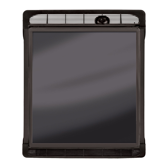
Summary of Contents for Norcold DC0040
- Page 1 Refrigerator Service Manual Models: DC0040(K), DC0051(K) DE0040, DE0051 DE0240T, DE0251T Norcold, Inc. P.O. Box 4248 Sidney, OH 45365-4248 Part No.623011A(08/03)
-
Page 2: Wiring Schematic
Troubleshooting – Table of Contents Ø Procedure A – Thermostat “ON” compressor does not run… 3 Ø Procedure B – Compressor resistance……………………….. 4 Ø Procedure C – Power supply output voltage…………………. 5 Ø Procedure D – Compressor amp draw………………………… 6 Ø... -
Page 3: Troubleshooting - Procedure A
Troubleshooting – Procedure A Change DC Thermostat “ON” Compressor Does Not Run Short Circuit OPERATION Power Supply Check AC Power Supply Change DC DC 0V Short Circuit (37 – 45V DC) Power Supply OPERATION GOOD (See Figure 5) Change AC Measure Terminal Power Supply Is Temperature... -
Page 4: Troubleshooting - Procedure B
Troubleshooting – Procedure B Compressor Resistance Measure Internal Compressor Change Compressor ¥ W Resistance Cooling Unit Failure (See Figure 3) 1.4 – 3.5 W Normal Procedure C Note: Perform procedure at room temperature. Turn the refrigerator to OFF. Remove the black wire to the compressor. Measure the resistance of the compressor between point A and point B. -
Page 5: Troubleshooting - Procedure C
Troubleshooting – Procedure C Power Supply Output Voltage DC Power Change DC Supply Failure Power Supply OPERATION Check AC Power Less than Supply. DC Power Change DC 15V AC (37 – 45V DC) Supply Failure Power Supply OPERATION GOOD (See Figure 5) Change AC Power Supply Measure Voltage... -
Page 6: Troubleshooting - Procedure D
Troubleshooting – Procedure D Compressor Amp Draw 40Watt < 1.6Amps Compressor Change Failure Cooling Unit 60Watt < 2.7Amps Measure Amperage at 40Watt = 1.6 - 2.0Amps ‘A’ on the Compressor Normal (See Figure 6) 60Watt = 2.7 - 3.3Amps 40Watt > 2.0Amps Compressor Change Failure... -
Page 7: Troubleshooting - Procedure E
Troubleshooting – Procedure E Thermistor Operation Verification To measure the resistance of the Table 1 for a listing of acceptable evaporator thermistor, turn the resistance ranges. refrigerator to the OFF position. In general: Disconnect the three-pole connector 1.6K – 29K = good thermistor. -
Page 8: Troubleshooting - Procedure F
Troubleshooting – Procedure F Insufficient Cooling Note: Check input voltage before do not short the wires; this will proceeding. Refer to Procedure A. damage the power supply. Ø Make sure the ventilation vents are If compressor runs continuously: not blocked. Refer to Procedure I. Ø... - Page 9 Ventilation – Procedure I Ventilation is necessary for the correct will not cool correctly. Do not block the operation of the refrigerator. Good vents by closet or cabinet doors. Vent ventilation also increases the life of the blockage that reduces the vent area can refrigerator cooling system.
-
Page 10: Troubleshooting - Quick Reference
Troubleshooting – Quick Reference 1. Check for supply voltage at rear of the refrigerator. Turn refrigerator ON. The operating voltage should be between 10.5V and 32V DC. There will be some variation in these readings depending on the supply voltage. 2.


Need help?
Do you have a question about the DC0040 and is the answer not in the manual?
Questions and answers