Table of Contents
Advertisement
Quick Links
Advertisement
Table of Contents

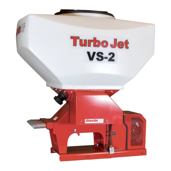
Summary of Contents for Stocks AG Turbo Jet Series
- Page 35 Turbo Jet 10..7 minimum – 20 maximum PLEASE RECORD THE SERIAL NUMBER, DATE OF PURCHASE, AND DEALER DETAILS. DATE..........SERIAL NUMBER........DEALER......................Manufactured by Stocks AG Limited, Cromwell Road, Wisbech, Cambridgeshire, PE14 0SD, UK Tel: 01945 464909 Fax: 01945 464985. EMAIL sales@stocks-ag.co.uk WEBSITE www.stocks-ag.co.uk...
- Page 36 Contents Page 2 Fitting to your implement Page 3-4 Hopper Spreader plates Flexible tubes C rail Electric connections and controls Page 5-7 Head Unit GPS sensor Remote Finger Switch Main power Junction box Fans Agitator Feed motor Feed rolls and selection Page 7-10 Grass seed rolls Small seed rolls...
- Page 37 STOCKS TURBO JET FITTING GUIDE. Please read these notes before fitting the Turbo Jet to your implement. The Turbo Jet can be used for a wide variety of seeding applications in conjunction with a wide variety of parent implements. It is not practical to supply tailored mounting brackets for every implement on the market, and so the final attachment of the Turbo Jet to the implement is the responsibility of the user.
- Page 38 Spreader Plates The Turbo Jet has 8 or 10 outlet pipes that can be split into two using the black plastic “Y” connector, to give 16 or 20 spreader plates. Depending on the implement width and if you require a broadcast or band sown effect, use as many outlets as required, with or without the spreaders.
- Page 39 ELECTRIC CONNECTIONS AND CONTROLS HEAD UNIT. Refer to the RDS -CON Control System manual for detailed instructions regarding the fitting, installation, and operation of the Head Unit. GPS RECEVER. (GPS16) Refer to the detailed GPS Fitting Instructions provided with each GPS receiver. The standard supplied GPS receiver connects directly into the -CON head unit situated in the tractor cab –...
- Page 40 REMOTE CUT OUT SWITCH. Refer to the detailed instructions for the Remote Mounted Cut Out Finger Switch to the rear of this manual. Page 13. It is optional whether you use this switch for automatic ON/OFF of the feed motor, or you may choose not to fit it, and use manual control from the in-cab head unit.
- Page 41 Feed Motor The feed motor can be turned ON or OFF from either manually via the head unit touch screen, or automatically by the remote mounted spring finger switch which can be fitted to the linkage or the implement. The feed motor must be switched ON via the head unit for the spring finger switch to work automatically.
- Page 42 GRASS SEED ROLLS Use for grass seed and grass seed mixes. The standard roll is an 8 section roll - use all 8 with the appropriate spacers. Do not fit any stainless steel discs with these. Remember to use the agitator when calibrating and seeding grass.
- Page 43 White Standard Spacers –There are 2 x 3mm white small end spacers, 4 x white mid spacers, and 3 x white large spacers – these always stay in the same order and position whatever the combination of 5mm Small Seed rolls and black roll spacers. 5mm Small Seed Rolls and Stainless Steel Discs.
- Page 44 IMAGE 1 IMAGE 2 IMAGE 3 IMAGE 4 IMAGE 1: Illustrates 1 x 5mm feed roll with stainless discs to outside + 2 x black spacers. IMAGE 2: Illustrates 2 x 5mm feed roll with stainless discs to outside + 1 x black spacers. IMAGE 3: Illustrates 3 x 5mm feed roll with stainless discs to outside + 0 x black spacers.
- Page 45 OPERATING AND CALIBRATION INSTRUCTIONS Safety First - Keep clear when operating.The moving parts of this machine are powerful and can pull in a finger or clothing. Be especially careful whilst performing calibration tests. To assist filling the hopper, if necessary fabricate and fit a work platform and steps, complete with handrails. If using agrochemicals, read the label before you buy, use pesticides safely and wear suitable protective clothing and aspirators.
- Page 46 The Speed Range Ensure you check the minimum and maximum speeds displayed, and that they are sensible for your field operation. This is the speed range that the -CON can maintain the required application rate, and depends on the width of your machine, the application rate required, and the type and configuration of feed rolls fitted.
- Page 47 Please contact your distributor or dealer for help and advice, or in the event of any problem or before attempting any repair. If you still require assistance, please contact Stocks AG directly. Stocks AG Wizard control system. REMOTE MOUNTED CUT OUT FINGER SWITCH...


Need help?
Do you have a question about the Turbo Jet Series and is the answer not in the manual?
Questions and answers