
Related Manuals for Allen-Bradley 1761-NET-AIC


Summary of Contents for Allen-Bradley 1761-NET-AIC
- Page 1 AIC+ Advanced Interface Converter Catalog Number 1761-NET-AIC User Manual Allen-Bradley Spares...
- Page 2 BURN HAZARD or motor, to alert people that surfaces may be at dangerous temperatures. Allen-Bradley, PLC, SLC, MicroLogix, PanelView, DTAM, and Rockwell Automation are trademarks of Rockwell Automation, Inc. Trademarks not belonging to Rockwell Automation are property of their respective companies.
- Page 3 To help you find new and updated information in this release of the manual, we have included change bars as shown to the right of this paragraph. Topic Page Updated publication list Ordering publications Processor/cable compatibility 16...19 Allen-Bradley Spares Publication 1761-UM004B-EN-P - June 2006...
- Page 4 Summary of Changes Publication 1761-UM004B-EN-P - June 2006...
-
Page 5: Table Of Contents
Diagnostics ........31 Allen-Bradley Spares... - Page 6 Table of Contents Appendix A Specifications and Dimensions General Specifications ......33 Hardware Handshaking .
-
Page 7: Preface
You should have a basic understanding of SLC 500 and MicroLogix products and be able to interpret the ladder-logic instructions required to control your application. If you do not, contact your local Allen-Bradley representative for information on available training courses before using this product. Purpose of This Manual This manual is a reference guide for the Advanced Interface Converter (AIC+). -
Page 8: Additional Resources
A guide to wiring and grounding guidelines Industrial Automation Wiring and Grounding 1770-IN041 Guidelines A glossary of industrial automation terms and abbreviations Allen-Bradley Industrial Automation Glossary AG-7.1 If you would like a manual, you can: • download a free electronic version from the Internet at http://literature.rockwellautomation.com. -
Page 9: Product Overview
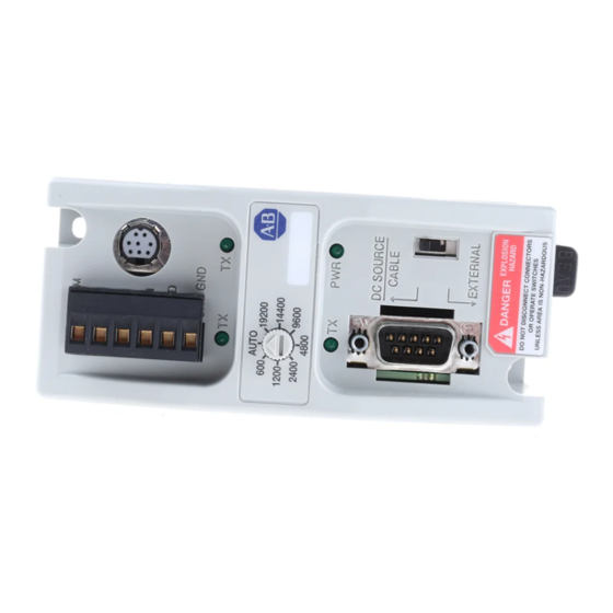
The dc power-source selector switch needs to be set for your particular configuration. See Network Diagrams starting on page 21 for more details on how to wire and configure the AIC+ interface converter. Allen-Bradley Spares Publication 1761-UM004B-EN-P - June 2006... -
Page 10: Operation Modes
Product Overview The communication-rate selector switch is used to match the communication rate filter of the AIC+ interface converter to the network communication rate. This switch does not change the network communication rate and is normally left in the AUTO position. - Page 11 Use this area to mark the node address of The node address is each connection. configured in the device connected with this port. Allen-Bradley Spares Publication 1761-UM004B-EN-P - June 2006...
- Page 12 Product Overview Publication 1761-UM004B-EN-P - June 2006...
-
Page 13: Installation And Wiring
Programmable Controllers, Part 2 – Equipment Requirements and Tests. For specific information required by EN 61131-2, see the appropriate sections in this publication, as well as the Industrial Automation Wiring and Grounding Guidelines, publication 1770-IN041. Allen-Bradley Spares Publication 1761-UM004B-EN-P - June 2006... -
Page 14: Safety Considerations
Installation and Wiring Safety Considerations This equipment is suitable for use in Class I, Division 2, Groups A, B, C, D, or nonhazardous locations only. Explosion Hazard — ATTENTION Substitution of components may impair suitability for Class I, Division 2. Do not replace components or disconnect equipment unless power is switched off and the area is known to be nonhazardous. -
Page 15: Mount The Aic+ Advanced Interface Converter
1. Place a screwdriver in the DIN-rail latch at the bottom of the AIC+ interface converter. 2. Holding the AIC+ interface converter, pry downward on the latch until the AIC+ interface converter is released from the DIN rail. Allen-Bradley Spares Publication 1761-UM004B-EN-P - June 2006... -
Page 16: Mount To A Panel
Installation and Wiring Side View DIN Rail Mount to a Panel Follow these instructions to mount your AIC+ interface converter to a panel. 1. Remove the mounting template from this document. 2. Secure the template to the mounting surface. 3. Drill holes through the template. 4. -
Page 17: Wire The Aic+ Advanced Interface Converter
Always connect the CHS GND (chassis ground) terminal to the nearest earth ground. This connection must be made whether or not an external 24V dc supply is used. Allen-Bradley Spares Publication 1761-UM004B-EN-P - June 2006... -
Page 18: Wire To The Network Ports
Installation and Wiring Wire to the Network Ports Use these instructions for wiring Belden cable. Attach the RS-485 Connector to the Communication Cable A daisy-chained network is recommended. Other chained IMPORTANT networks are not recommended. Daisy-chain Network Belden Belden Belden #3106A or #3106A or #3106A or... - Page 19 This connects the termination impedance (120 Ω) that is built into each AIC and AIC+ interface converter as required by the RS-485 specification. End of Line Termination Jumper Jumper Belden #3106A or #9842 Cable 1219 m (4000 ft) Maximum Jumper Allen-Bradley Spares Publication 1761-UM004B-EN-P - June 2006...
-
Page 20: Cable Choices
Installation and Wiring Cable Choices This section provides information that will help you determine the appropriate cable for your application. 1761-CBL-AC00 and 1747-CP3 Cable 1747-CP3 1761-CBL-AC00 1761-CBL-AC00 and 1747-CP3 Cable Cable Length Connects from to AIC+ Interface Converter 1747-CP3, 3 m (9.8 ft), SLC 5/03, SLC 5/04, or SLC 5/05 RS-232 (DB-9, 1761-CBL-AC00... - Page 21 1761-CBL-HM02 (6.5 ft) processors port RS-232 (8-pin RS-232 (8-pin External mini-DIN) mini-DIN) communication communication port on another port AIC+ interface converter or MicroLogix 1100 Series B cables are required for hardware handshaking. Allen-Bradley Spares Publication 1761-UM004B-EN-P - June 2006...
- Page 22 Installation and Wiring 1761-CBL-AP00 and 1761-CBL-PM02 Cable 1761-CBL-PM02 1761-CBL-AP00 1761-CBL-AP00 and 1761-CBL-PM02 Cable Cable Length Connects External Selection Power Switch from to AIC+ Supply Setting Interface Required Converter 1761-CBL-AP00, 45 cm, SLC 5/03, SLC RS-232 (8-pin External (17.7 in.), 5/04, or SLC mini-DIN) 5/05 communication...
-
Page 23: Recommended User-Supplied Components
NULL modem adapter Standard AT Straight through 9 pin RS-232 User-supplied cable cable User-supplied Components DB-9 RS-232 1761-CBL-AP00 or 1761-CBL-PM02 DH-485 Connector Port 1 Port 3 Cable Straight-D Connector Port 2 6 7 8 Allen-Bradley Spares Publication 1761-UM004B-EN-P - June 2006... - Page 24 An 8-pin mini-DIN connector is used for making connections to the RS-232 (8-pin mini-DIN) communication port. This connector is not commercially available. If you are making a cable to connect to the RS-232 (8-pin mini-DIN) communication port, you must configure your cable to connect to the Allen-Bradley cable. Publication 1761-UM004B-EN-P - June 2006...
-
Page 25: Network Connections
1000 Processor 1761-CBL-AM00 or 1761-CBL-HM02 Cable AIC+ Converter 1747-CP3 or 1761-CBL-AC00 Cable 24V dc (Not needed in this configuration since the MicroLogix 1000 processor provides power to the RS-232 (8-pin mini DIN) com port.) Allen-Bradley Spares Publication 1761-UM004B-EN-P - June 2006... -
Page 26: Components Replaced By The Aic+ Interface Converter
Network Connections Components Replaced by the AIC+ Interface Converter The AIC+ interface converter replaces the combination of a 1747-PIC interface converter and 1747-AIC isolated link coupler in most applications. Components Replaced by the AIC+ Interface Converter DH-485 Network using 1747-AIC Interface Converter SLC 5/04 Processor 24V dc Power 1747-PIC... -
Page 27: Dh-485 Network With Slc 5/03 And Slc 5/04 Processors And A Pc
1761-CBL-AP00 or 1761-CBL-PM02 Cable AIC+ Converter AIC+ Converter 1747-CP3 or 1761-CBL-AC00 Cable 24V dc (user supplied) 1747-AIC Isolated 1747-AIC Isolated SLC DH-485 Network Link Coupler Link Coupler SLC 5/02 Processor SLC 5/03 Processor Allen-Bradley Spares Publication 1761-UM004B-EN-P - June 2006... -
Page 28: Dh-485 Network With A Micrologix 1000 Controller
Network Connections DH-485 Network with a MicroLogix 1000 Controller DH-485 Network with a MicroLogix 1000 Controller MicroLogix 1000 Processor (series C or later) Connection from Port 1 or Port 2 to MicroLogix 1000 Processor 1761-CBL-AM00 or 1761-CBL-HM02 Cable 1747-CP3 or 1761-CBL-AP00 or AIC+ Converter 1761-CBL-AP00 or... -
Page 29: Networked Operator-Interface Device And Micrologix Controller
1761-CBL-AM00 or 1761-CBL-HM02 Cable 24V dc (Not needed in this configuration since the MicroLogix 1000 provides MicroLogix 1000 Processor (series C or later) power to the AIC+ SLC 5/03 Processor via port 2.) Allen-Bradley Spares Publication 1761-UM004B-EN-P - June 2006... -
Page 30: Networks Using Ganged Converters
Network Connections Networks Using Ganged Converters Networks Using Ganged Converters DH-485 Network with PanelView Interface PanelView Interface 1761-CBL-AM00 or RJ45 Port 1761-CBL-HM02 Cable 1761-CBL-AS09 or 1761-CBL-AS03 Cable AIC+ Converter AIC+ Converter 24V dc 24V dc (user supplied) (user supplied) 1747-CP3 or 1761-CBL-AC00 Cable DH-485 Network SLC 500 Fixed Controller... -
Page 31: Network Extended To 2438 M (8000 Ft)
AIC+ Converter 24V dc 24V dc (User supplied or (User supplied or from 24V dc terminals from 24V dc terminals on SLC controller.) on SLC controller.) DH-485 Network 1219 m (4000 ft), Maximum Allen-Bradley Spares Publication 1761-UM004B-EN-P - June 2006... -
Page 32: Df1 Master-Slave Network With Modem
Network Connections DF1 Master-slave Network with Modem DF1 Master-slave Network with Modem SLC 5/03 Processor SLC 5/03 Processor 1761-CBL-AP00 or 1761-CBL-AP00 or 1761-CBL-PM02 Cable Master Slave 1761-CBL-PM02 Cable Radio Modem AIC+ Converter AIC+ Converter or Lease Line Straight 9...25 Pin Cable Straight Radio Modem 9...25... -
Page 33: Avoid Incorrect Connections
1761-CBL-AS09 or DH-485 1761-CBL-AS03 Cable Network AIC+ Converter 1761-CBL-AS09 or 1761-CBL-AS03 Cable 1747-AIC Isolated Link Coupler DH-485 Network SLC 5/03 Processor In this configuration, the cable will fit but not function properly. IMPORTANT Allen-Bradley Spares Publication 1761-UM004B-EN-P - June 2006... - Page 34 Network Connections Publication 1761-UM004B-EN-P - June 2006...
-
Page 35: Interpret The Led Indicators
RS-232 (8-pin mini-DIN) communication port. External 24V dc power supplied to AIC+ interface converter from external source (use 24V dc power from SLC or user-supplied 24V dc power supply). Allen-Bradley Spares Publication 1761-UM004B-EN-P - June 2006... -
Page 36: Publication 1761-Um004B-En-P - June
Interpret the LED Indicators Publication 1761-UM004B-EN-P - June 2006... -
Page 37: General Specifications
Appendix Specifications and Dimensions General Specifications AIC+ Advanced Interface Converter - 1761-NET-AIC Attribute Value 24V dc Power Source 20.4...28.8V dc Requirement Current Draw 0...120 mA 200 mA inrush current, max Internal Isolation (see below) 500V dc • Number of nodes, max = 32 per multidrop network DH-485, DF1, or User Network •... -
Page 38: Hardware Handshaking
Specifications and Dimensions Isolation Between All Ports and Power Supply Terminals RS-485 Communication RS-232 (8-pin mini-DIN) Port (Phoenix Plug) Communication Port RS-232 (DB-9, DTE) Communication Port Terminals for external 24V dc power supply and chassis ground. Hardware Handshaking To implement hardware handshaking, use cables that support the following signals. -
Page 39: Auto Transmit Delay (Turnaround Time) Per Communication Rate
Auto Transmit Delay is measured from the time the AIC+ interface converter transmits its last mark out of the RS-485 port, until the delay time expires. The AIC+ interface converter will not accept RS-485 port data during the Auto Transmit Delay time. Allen-Bradley Spares Publication 1761-UM004B-EN-P - June 2006... -
Page 40: Mounting Template
Specifications and Dimensions Mounting Template 52.07 mm (2.05 in.) 107 mm (4.20 in.) 118 mm (4.64 in.) Allow 15 mm (0.6 in.) clearance for DIN-rail latch movement during installation and removal. 27.7 mm (1.09 in.) Publication 1761-UM004B-EN-P - June 2006... - Page 41 19 LED indicators 31 who should use this manual 3 wire mount the AIC+ Advanced Interface network port 14 Converter power supply 13 DIN rail 11 panel mount 12 mounting template 36 Allen-Bradley Spares Publication 1761-UM004B-EN-P - June 2006...
- Page 42 Index Publication 1761-UM004B-EN-P - June 2006...
- Page 43 ___No, there is no need to contact me ___Yes, please call me ___Yes, please email me at _______________________ ___Yes, please contact me via _____________________ Return this form to: Rockwell Automation Technical Communications, 1 Allen-Bradley Dr., Mayfield Hts., OH 44124-9705 Allen-Bradley Spares Fax: 440-646-3525 Email: RADocumentComments@ra.rockwell.com...
- Page 44 PLEASE FASTEN HERE (DO NOT STAPLE) Other Comments PLEASE FOLD HERE NO POSTAGE NECESSARY IF MAILED IN THE UNITED STATES BUSINESS REPLY MAIL FIRST-CLASS MAIL PERMIT NO. 18235 CLEVELAND OH POSTAGE WILL BE PAID BY THE ADDRESSEE 1 ALLEN-BRADLEY DR MAYFIELD HEIGHTS OH 44124-9705...
- Page 45 Allen-Bradley Spares...
- Page 46 Rockwell Automation Rockwell Automation provides technical information on the Web to assist you in using its products. At http://support.rockwellautomation.com, you can Support find technical manuals, a knowledge base of FAQs, technical and application notes, sample code and links to software service packs, and a MySupport feature that you can customize to make the best use of these tools.
Need help?
Do you have a question about the 1761-NET-AIC and is the answer not in the manual?
Questions and answers