
Related Manuals for Hioki LR8400-20


Summary of Contents for Hioki LR8400-20
- Page 1 Instruction Manual LR8400-20 LR8401-20 LR8402-20 MEMORY HiLOGGER July 2014 Revised edition 7 LR8400B980-07 14-07H...
- Page 3 The HiLogger firmware version is displayed at the upper right on the System screen. The latest version can be downloaded from Hioki’s website. Please visit our company’s website or contact your dealer or Hioki representative for the version upgrade procedure.
-
Page 5: Table Of Contents
Contents Contents Introduction ................1 Confirming Package Contents ..........2 Safety Information..............3 Operating Precautions.............6 Chapter 1 Overview ____________________________________13 Product Overview and Features ......13 Measurement Flow ..........14 Names and Functions of Parts, Screen Configurations ............16 Basic Operation ............22 Screen Operations (changing settings, scrolling waveforms, and displaying values) ............22 ... - Page 6 Contents Connecting Alarm Outputs ..........41 +12 V Output Connection (for external sensors) ....42 External Control (using TRIG OUT and EXT TRIG) ..43 Turning the Power On and Off ....... 44 Inserting a CF Card or USB Flash Drive (when saving data) ..........
- Page 7 Contents Entering Titles and Comments (as needed) ..71 Suppressing Noise (Enable Digital Filtering) ..73 Viewing and Editing with the All-Channel Settings List .............74 Batch Copying Channel Settings ........75 Batch Setting Waveform Display/Hide and Waveform Color Settings for All Channels ........76 ...
- Page 8 Contents Types of Trigger Criteria ..........100 Enable the Trigger Function ........... 101 Key Setting Procedure ........... 101 Setting Trigger Criteria ........... 102 Selecting Triggering Criteria (Trigger Source) ....105 Using External Triggering ..........106 ...
- Page 9 Contents Transferring Data to a PC (USB Drive Mode) ..140 Select the USB Drive Mode ...........140 Connecting the USB Cable ..........141 Chapter 7 Numerical Calculations/Waveform Calculations ____________________________________________ 143 Calculate Average, Maximum, Minimum, and Etc. .143 Key Setting Procedure ...........144 ...
- Page 10 Contents Set Alarm Event Marking ..........157 Making System Settings ........158 Setting the Date and Time ..........158 Initializing the HiLogger (System Reset) ......159 Self-Test ................. 160 Chapter 9 External Control ___________________________ 161 External Trigger Input .......... 161 External Signal Output (Trigger Output) ....
- Page 11 E-Mail Sending Authentication ........222 10.8 About Communications Commands ....223 Configuring Communications Command Operation ..223 Chapter 11 Specifications_____________________________ 225 11.1 LR8400-20, LR8401-20, LR8402-20 Memory HiLogger Specifications ........225 11.2 LR8500 Voltage/Temp Unit Specifications ..240 11.3 LR8501 Universal Unit Specifications ....241 Chapter 12...
- Page 12 viii Contents Appendix____________________________________ A1 Appendix 1 Scan Timing .............A1 Appendix 2 Error Messages and Remedial Actions ..A2 Appendix 3 File Naming ............A8 Appendix 4 Text File Internal Format .........A9 Appendix 5 Binary File Size Calculation......A10 Appendix 6 List of Default Settings........A11 Appendix 7 Maximum Recordable Time ......A12 Appendix 8 Concerning Noise Countermeasures ..A13 Appendix 9 Frequently Asked Questions ......A19...
-
Page 13: Contents
Introduction Introduction Thank you for purchasing the Hioki Model LR8400-20, LR8401-20, LR8402-20 Mem- ory HiLogger.To obtain maximum performance from the HiLogger, please read this manual first, and keep it handy for future reference. The following documents are provided with this HiLogger. Refer to them as appro- priate for your application.The following documents are provided with this HiLog-... -
Page 14: Confirming Package Contents
LR8401 (with two Model LR8501 Universal Unit) LR8402 (with combined units, and UNIT1 is an LR8501 Universal Unit) Options Contact your dealer or Hioki representative for details. LR8500 Voltage/Temp Unit 9727 PC Card (256MB) LR8501 Universal Unit ... -
Page 15: Safety Information
Safety Information Safety Information This HiLogger is designed to comply with IEC 61010 Safety Stan- dards, and has been thoroughly tested for safety prior to shipment. However, mishandling during use could result in injury or death, as well as damage to the HiLogger. Using the HiLogger in a way not described in this manual may negate the provided safety features.... - Page 16 Safety Information Symbols for Various Standards This symbol indicates that the product conforms to regulations set out by the EC Directive. This is a recycle mark established under the Resource Recycling Promotion Law (only for Japan). Ni-MH WEEE marking: This symbol indicates that the electrical and electronic appliance is put on the EU market after August 13, 2005, and producers of the Member States are required to display it on the appliance under Article 11.2 of Directive 2002/96/EC (WEEE).
- Page 17 Safety Information Measurement categories This HiLogger complies with CAT II (300 VAC, DC) safety requirements. To ensure safe operation of measurement instruments, IEC 61010 establishes safety standards for various electrical environments, categorized as CAT II to CAT IV, and called measurement categories.
-
Page 18: Operating Precautions
• Before using the HiLogger the first time, verify that it operates normally to ensure that no damage occurred during storage or shipping. If you find any damage, contact your dealer or Hioki representative. • Before using the HiLogger, make sure that the insulation on the cables is undamaged and that no bare conductors are improperly exposed. - Page 19 Operating Precautions Handling the Instrument To avoid electric shock, do not remove the HiLogger's case. The internal components of the HiLogger carry high voltages and may become very hot during operation. Touching any of the high-voltage points inside the HiLogger is very dangerous.
- Page 20 Be sure to observe the following precautions. Incorrect handling may result in liquid leaks, heat generation, ignition, bursting and other hazards. • Use only the Hioki Model Z1000 Battery Pack. We cannot accept responsibility for accidents or damage related to the use of any other batteries.
- Page 21 Operating Precautions • The battery pack is subject to self-discharge. Be sure to charge the bat- tery pack before initial use. • The battery pack is a consumable. If the battery capacity remains very low after correct recharging, the useful battery life is at an end. •...
- Page 22 When an abnormal measurement value is observed, please contact your dealer or Hioki representative for inspection. • Measurements may be affected by noise or other electromagnetic ingress if input leads are longer than about three meters.
- Page 23 CF card/USB flash drive. • Although real-time saving to USB flash drive is supported, a CF card is recommended for data preservation. Performance cannot be guaranteed when using storage media other than a Hioki-specified CF card option.
- Page 24 Never use abrasives or solvent clean- ers. • Hioki shall not be held liable for any problems with a PC system that arises from the use of this CD, or for any problem related to the purchase...
-
Page 25: Chapter 1 Overview
1.1 Product Overview and Features Chapter 1 Overview 1.1 Product Overview and Features The portable data logger is expandable from 30 to 60 channels. Data variations can be observed on the high-resolution color LCD screen, and monitored on a PC con- nected via LAN or USB. -
Page 26: Measurement Flow
1.2 Measurement Flow 1.2 Measurement Flow 1. Preparations for Measurement (p. 27) 1. Attach Expansion Units (as needed) 4. Connecting Front Rear Panel Panel 2. Install the To save data, Battery Pack insert a CF card/USB flash drive. Right 3. - Page 27 1.2 Measurement Flow Configure Input Channels (p. 53) Select input channels, and set input types and measurement ranges. Make other settings as needed. Waveform Display (p. 65) Scaling (p. 69) Titles and Comments (p. 71) Noise Suppression (p. 73) ...
-
Page 28: Names And Functions Of Parts, Screen Configurations
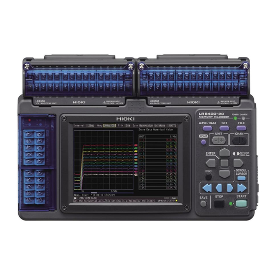
Universal Unit Voltage/Temp Unit Use to measure voltage, thermocouple temper- Use to measure voltage, thermocouple ature, humidity (with the Hioki Z2000 Humidity temperature, and humidity (with the Hioki Sensor), resistance, and temperature with resis- Z2000 Humidity Sensor) (p. 33). tance temperature detectors (RTDs) (p. 33). - Page 29 1.3 Names and Functions of Parts, Screen Configurations Operating Keys/LED HiLogger Status Indicators CHARGE POWER Lights while charging the Z1000 Battery Pack Lights when powered on (p. 44). (p. 31). Setup and display Choose a screen CHAN ...
- Page 30 1.3 Names and Functions of Parts, Screen Configurations Right Side CF Card Slot USB Port Use to save data to a CF card. Use to save data to a USB flash drive. Insert an optional CF card (p. 46). Insert an USB flash drive (p.
- Page 31 1.3 Names and Functions of Parts, Screen Configurations Waveform/Numerical Screens The screen switch- es each time you press the key. (7 display types) [Gauge+Wave] Screen [Wave] Screen [Gauge+Wave] Measurement data is displayed as Measurement data is displayed waveforms with gauges (p. 86). as waveforms (p.
- Page 32 1.3 Names and Functions of Parts, Screen Configurations About the Icons (on all screens) (Bottom of the screen) CF card, USB flash drive Clock Displayed when a CF card/USB flash "Setting the Date and Time" (p. 158) drive is inserted. The icon appears red Power source indicator when accessing the CF card/USB Indicates the HiLogger's power source.
- Page 33 1.3 Names and Functions of Parts, Screen Configurations Settings Screens The screen switch- es each time you press the key. (7 display types) [Setting] Screen [CH] Screen Press the left/right Make settings for recording (p. 50). Make input channel settings while keys to select be- Set numerical calculation, auto- viewing the monitor display (p.
-
Page 34: Basic Operation
1.4 Basic Operation 1.4 Basic Operation Screen Operations (changing settings, scrolling waveforms, and displaying values) Changing screen contents Select the item to change. Show available set- Setting Screen ting options. Select the desired setting. Apply the new set- ting, or cancel it. Waveform/Numerical Screen Scrolling a waveform Hide A/B cursors... -
Page 35: Starting And Stopping Measurement
1.4 Basic Operation Starting and Stopping Measurement Start measuring (acquiring measurement data) as follows. When saving is enabled, data is recorded to the specified removable storage (CF card or USB flash drive) as it is being recorded to internal memory. Start Measurement Press START. - Page 36 1.4 Basic Operation About Measuring Operation About Continuous and Repeating Recording: (p. 50) See: Press START Press STOP Repeat: Off Repeat: On Cont. Recording Recording time time Measuring Measuring Start Start Stop Stop Measuring Measuring Measuring Dead time Measuring Recording Recording time time...
-
Page 37: Disabling Key Operations (Key-Lock Function)
1.4 Basic Operation Disabling Key Operations (Key-Lock Function) Keys can be disabled to avoid inadvertent operations. Press and hold the right and left cursor keys for three seconds to lock the other keys, and repeat to unlock. Performing Zero Adjustment With the Waveform/Numerical or [CH] screen displayed,... -
Page 38: Confirming Inputs (Monitor)
1.4 Basic Operation Confirming Inputs (Monitor) You can confirm the status of inputs and display ranges with the current settings (data is not acquired to internal memory). This function is convenient for checking measured values before activating real-time sav- ing. Unit Press MONIT... -
Page 39: Measurement Preparations
Measurement Chapter 2 Preparations Attach expansion input units (as needed) (p. 28) Make connections (p. 33) Install the Battery Pack (option) (as needed) (p. 30) Connect the AC adapter (p. 32) Turn the power on (To save data) Insert a CF card or USB (p. -
Page 40: Attaching Expansion Input Units (As Needed)
Measurement Parameter • Voltage • Voltage • Temperature (thermocouple or resistance • Temperature (thermocouple) temperature sensor) • Humidity (using Hioki Z2000 Humidity Sen- • Humidity (using Hioki Z2000 Humidity Sen- sor) sor) • Resistance M3 screw terminal block Input channels: 15... - Page 41 2.1 Attaching Expansion Input Units (as needed) Installation Procedure • To avoid electric shock accidents or damage, turn off the HiLogger and remove the cables before attaching or detaching. • To avoid electric shock accidents or damage, ensure that the connec- tors are secured with the screws.
-
Page 42: Using The Battery Pack (Option)
2.2 Using the Battery Pack (Option) If commercial power is not available when the AC adapter is connected, the LR8400-20, LR8401-20, LR8402-20 Memory HiLogger can operate from the Model Z1000 Battery Pack, so when using commercial power, the battery pack serves as a backup supply during power outages. -
Page 43: Charge The Battery Pack
2.2 Using the Battery Pack (Option) Charge the Battery Pack Regardless of whether the Memory HiLogger is on or off, the battery pack recharges whenever the 9418-15 AC Adapter is plugged in to a power source (p. 32). Therefore, charging is provided by merely keeping the battery installed in the Memory HiLogger. -
Page 44: Connecting The Ac Adapter
2.3 Connecting the AC Adapter 2.3 Connecting the AC Adapter Connect the power cord and the HiLogger to the supplied Model 9418-15 AC Adapter, then plug the power cord into an outlet. When used with the battery pack installed, the battery serves as an operating backup supply in case of power failure, and the AC adapter otherwise has priority. -
Page 45: Making Connections
Is damage to the HiLogger evident? If damage is evident, re- quest repairs. When turning power on The power cord may be Does the HIOKI logo appear on the damaged, or the HiLogger screen? may be damaged internal- Nothing appears, ly. -
Page 46: Voltage And Thermocouple Temperature Measurement
2.4 Making Connections If connecting crimped terminals to the analog input terminals, use insulated terminals for M3 screws with the size shown below. 6 mm 6 mm max. max. Voltage and Thermocouple Temperature Measurement < Voltage/Temp Unit > Required items: phillips screwdriver (for M3 screws), measurement leads (for voltage measurement), or thermocouple (for temperature measurement) Loosen the screws in the ter- Replace the terminal block... - Page 47 2.4 Making Connections <Connecting to the terminals of the Universal Unit> Required items: phillips screwdriver (for M3 screws), flat-blade screwdriver (tip width 2.6 mm), measurement leads (for voltage measurement), or thermocouple (for temperature measurement) Recommended wire diameter:Single strand diameter:0.4 mm - 1.2 mm (AWG26-16) Multi-strand:0.2 mm - 0.75 mm (AWG24-20)...
-
Page 48: Temperature Measurement With A Resistance Temperature Detector (Rtd)
2.4 Making Connections Temperature Measurement with a Resistance Temperature Detector (RTD) <Connecting to the terminals of the Universal Unit> Required items: phillips screwdriver (for M3 screws), flat-blade screwdriver (tip width 2.6 mm), RTD Recommended wire diameter:Single strand diameter:0.4 mm - 1.2 mm (AWG26-16) Multi-strand:0.2 mm - 0.75 mm (AWG24-20)... -
Page 49: Humidity Measurement
2.4 Making Connections Humidity Measurement <Connecting to the terminals of the Voltage/Temp Unit> Required items: phillips screwdriver (for M3 screws), Hioki Z2000 Humidity Sensor With a Phillips screwdriver, Replace the terminal block loosen the screws in the termi- cover on the Voltage/Temp nal block cover of the Voltage/ Unit, and tighten the screws. - Page 50 2.4 Making Connections <Connecting to the terminals of the Universal Unit> Required items: phillips screwdriver (for M3 screws), flat-blade screwdriver (tip width 2.6 mm), Hioki Z2000 Humidity Sensor With a Phillips screwdriver, With the button held in, insert loosen the screws in the termi-...
-
Page 51: Resistance Measurement
2.4 Making Connections Resistance Measurement <Connecting to the terminals of the Universal Unit> Required items: phillips screwdriver (for M3 screws), flat-blade screwdriver (tip width 2.6 mm), measurement leads Recommended wire diameter:Single strand diameter:0.4 mm - 1.2 mm (AWG26-16) Multi-strand:0.2 mm - 0.75 mm (AWG24-20)... -
Page 52: Pulse Measurement
2.4 Making Connections Pulse Measurement < Connecting to the external control terminals > Required items: phillips screwdriver (for M3 screws), measurement leads Lift the external control termi- Replace the cover on the exter- nal block cover. nal control terminal block. Loosen terminal block... -
Page 53: Connecting Alarm Outputs
2.4 Making Connections Connecting Alarm Outputs < Connecting to the external control terminals > Required items: phillips screwdriver (for M3 screws), measurement leads Lift the external control termi- Replace the cover on the exter- nal block cover. nal control terminal block. Connect the '+' wire to the ALM1 (or Loosen terminal... -
Page 54: Output Connection (For External Sensors)
2.4 Making Connections +12 V Output Connection (for external sensors) < Connecting to the external control terminals > Required items: phillips screwdriver (for M3 screws), measurement leads Lift the external control termi- Replace the cover on the exter- nal block cover. nal control terminal block. -
Page 55: External Control (Using Trig Out And Ext Trig)
2.4 Making Connections External Control (using TRIG OUT and EXT TRIG) < Connecting to the external control terminals > Required items: phillips screwdriver (for M3 screws), measurement leads Lift the external control termi- Replace the cover on the exter- nal block cover. nal control terminal block. -
Page 56: Turning The Power On And Off
2.5 Turning the Power On and Off 2.5 Turning the Power On and Off Be sure to read "Before Turning Power On" (p .7) before turning power Turning Power On Verify that the HiLogger and peripheral devices are correctly connected. Turn the power switch on ( ). -
Page 57: Inserting A Cf Card Or Usb Flash Drive (When Saving Data)
Important Performance specifications cannot be guaranteed when using storage media other than a Hioki-specified CF card option. • Hioki options PC cards (includes adapter) Note: The HiLogger does not support card slot adapters. 9727 PC Card 256M, 9728 PC Card 512M, 9729 PC Card 1G, 9830 PC Card 2G •... -
Page 58: Cf Card Insertion & Removal
2.6 Inserting a CF Card or USB Flash Drive (when saving data) CF Card Insertion & Removal Cover Inserting a CF card Open the CF card slot cover. Press the Eject button in if it is in the released position. HiLogger right side Face the CF card with the arrow mark ... -
Page 59: Formatting A Cf Card/Usb Flash Drive
2.6 Inserting a CF Card or USB Flash Drive (when saving data) Formatting a CF Card/USB flash drive The CF card or USB flash drive can be formatted by a PC or by the HiLogger. Format a new CF card or USB flash drive before use. This procedure describes how to format a CF card or USB flash drive in the HiLogger. -
Page 60: Compensating For Input Circuit Offset (Zero Adjustment)
2.7 Compensating for Input Circuit Offset (Zero Adjustment) 2.7 Compensating for Input Circuit Offset (Zero Adjustment) Zero adjustment corrects for voltage offset at the input terminals, so that Memory HiLogger measurements are relative to zero volts. Execute zero adjustment whenever input circuit offset is a concern. Turn on the power and wait for 30 minutes to stabilize the internal temperature of the HiLogger. -
Page 61: Chapter 3 Settings
3.1 Setting Flow Overview Chapter 3 Settings 3.1 Setting Flow Overview Configure measurement settings before starting to measure. Select the display method and configure auto saving as needed. After a measurement setting configuration has been saved (p. 131), you can start measuring immediately after loading the setting configuration data. -
Page 62: Configuring Measurement Settings
3.2 Configuring Measurement Settings 3.2 Configuring Measurement Settings Configure measurement settings on the [Setting] screen. The available measurement methods are Normal Recording, Continuous Recording and Repeat Recording. The Setting screen cannot be displayed while measuring. Start Measurement Stop Measurement Continuous Press STOP to stop measuring. - Page 63 3.2 Configuring Measurement Settings Recording Select the data acquisition interval. Interval Setting options:( : default setting) (Interval) 10ms, 20ms , 50ms, 100ms, 200ms, 500ms, 1s, 2s, 5s, 10s, 20s, 30s, 1min, 2min, 5min, 10min, 20min, 30min, 1h • When expansion input units are installed (as UNIT3 and UNIT4), the default setting is 50 ms.
- Page 64 3.2 Configuring Measurement Settings About the Recording Interval • Select the data acquisition interval to suit your measurement objectives. • Note that shorter recording intervals restrict the maximum recording time. • The minimum recording interval depends on the input unit (channels), and whether burn-out detection is enabled....
-
Page 65: Input Channel Settings
3.3 Input Channel Settings 3.3 Input Channel Settings Configure the input channel settings on the [CH] screen. The Setting screen cannot be displayed while measuring. Input channels are as follows. Each channel can provide the following measurements. •Voltage/Temp Unit (UNIT1 to UNIT4, each with analog waveform input channels CH1 to CH15) •Universal Unit (UNIT1 to UNIT4, each with analog waveform input channels CH1 to CH15) - Page 66 3.3 Input Channel Settings Unit Switching UNIT4 (pulse input and alarm output chan- (Analog input channel settings) UNIT1 nel settings) PLS & ALM (numerical calculation channel settings) CALC1 CALC2 and return to UNIT1 Channel Switching 1-15 ...
-
Page 67: Voltage Measurement Settings
3.3 Input Channel Settings Voltage Measurement Settings Configure these settings for each voltage measurement channel. "Key Setting Procedure" (p .53) See: Select the input unit (UNIT1 to 4) and channel : On to 4-15), and check the box to enable the chan- : Off nel. -
Page 68: Temperature Measurement Settings (Using Thermocouples)
3.3 Input Channel Settings Temperature Measurement Settings (using thermocouples) Follow this procedure to configure thermocouple temperature measurement channels. Make these settings on the [CH] screen. "Key Setting Procedure" (p .53) See: Select the input unit (UNIT1 to 4) and channel (1-1 to 4-15), and check the box to enable the channel. - Page 69 3.3 Input Channel Settings About Burn-Out Detection • When burn-out detection (Burn Out) is enabled (On), a tiny sensing current is applied during each recording interval during thermocouple measurements to detect broken wires. • Detection current is timed to avoid affecting measured values. •...
-
Page 70: Temperature Measurement Settings (For Rtds)
3.3 Input Channel Settings Temperature Measurement Settings (for RTDs) Follow this procedure to configure resistance temperature detector (RTD) measurement channels. Make these settings on the [CH] screen. "Key Setting Procedure" (p .53) See: : On Select the input unit (UNIT1 to 4) and channel : Off (1-1... -
Page 71: Humidity Measurement Settings
3.3 Input Channel Settings Humidity Measurement Settings Enable this channel setting for humidity measurement with the optional Z2000 Humidity Sensor. Make these settings on the [CH] screen. "Key Setting Procedure" (p .53) See: Select the input unit (UNIT1 to 4) and channel : On (1-1 to 4-15), and check the box to enable the... -
Page 72: Resistance Measurement Settings
3.3 Input Channel Settings Resistance Measurement Settings Make these channel settings for resistance measurement. Make these settings on the [CH] screen. "Key Setting Procedure" (p .53) See: Select the input unit (UNIT1 to 4) and channel : On (1-1 to 4-15), and check the box to enable the : Off channel. -
Page 73: Pulse Or Logic Measurement Settings
3.3 Input Channel Settings Pulse or Logic Measurement Settings Make these channel settings for pulse and logic measurements. (See "Integration (Count) Measurement Settings" (p .62) and "Revolution Measurement Settings" (p .63) for pulse measurements.) Make these settings on the [CH] screen. -
Page 74: Integration (Count) Measurement Settings
3.3 Input Channel Settings Integration (Count) Measurement Settings Configure these settings for each pulse channel receiving input from a pulse output device such as a watt-hour or flow meter. Make these settings on the [CH] screen. "Key Setting Procedure" (p .53) See: Select the input unit (PLS&ALM) and channel to P8), and check the box to enable the... -
Page 75: Revolution Measurement Settings
3.3 Input Channel Settings Revolution Measurement Settings Configure these settings for each pulse channel on which you will be counting pulses corresponding to revolutions, such as output from a rotary encoder or tachometer. The revolution measurement is obtained by counting the number of pulses input per second. Make these settings on the [CH] screen. -
Page 76: Data Saving Settings
3.4 Data Saving Settings Revolution Measurement Theory Pulse count is measured using the HiLogger's internal 10 ms sampling interval. 0 10 ms 20 ms P100 P200 Pulse Count The revolution rate (r) per second during time t [s] is obtained by dividing the number of pulses from (t-1) to t [s] by the number of pulses per revolution. -
Page 77: Waveform Display Settings (As Needed)
3.5 Waveform Display Settings (as needed) 3.5 Waveform Display Settings (as needed) Set the waveform display settings as needed. These settings can be changed on the Numerical/Waveform screen after measure- ment (p. 85). The Setting screen cannot be displayed while measuring. Key Setting Procedure Select the [CH]... -
Page 78: Specifying Vertical Display Range By Magnification And Zero Position (Vertical Axis Expansion/Compression)
3.5 Waveform Display Settings (as needed) Specifying Vertical Display Range by Magnification and Zero Position (vertical axis expansion/compression) The vertical display range and zero position can be specified for each channel. The magnification setting determines the displayed range. Waveforms are expanded or compressed vertically relative to the center of the screen. -
Page 79: Specifying The Vertical Display Range By Upper And Lower Limits (Expansion/Compression)
3.5 Waveform Display Settings (as needed) Specifying the Vertical Display Range by Upper and Lower Limits (expansion/compression) The vertical display range can be defined by upper and lower limits. Using this method, the voltage range does not need to be selected because the optimum range is selected automatically for the display. -
Page 80: Setting The Display Time Base (Horizontal Axis Magnification)
3.5 Waveform Display Settings (as needed) Setting the Display Time Base (horizontal axis magnification) Displayed waveforms can be expanded or compressed along the horizontal axis. Shorter setting values correspond to greater magnification. Make these settings on the [Setting] screen. "Time Setting by Key Operations" (p .50) See: Settings can be changed during and after measurement on the 1 div... -
Page 81: Scaling Settings (As Needed)
3.6 Scaling Settings (as needed) Scaling Settings (as needed) Use the scaling function to convert input volt- age to the physical units of the measurement parameter for display, such to convert voltage Normal Display Scaling Enabled input for display as electrical current. (Off) Converted values can be displayed in fixed or floating-point notation. - Page 82 3.6 Scaling Settings (as needed) Conversion Ratio Setting Method 2-Point Setting Method :High value Example Units (eu) :Converted Units: [A] high value Slope (Conversion Param 1:V value value :Low value ratio: eu/v) Param 2:V value value : Converted Offset low value Converted unit values...
-
Page 83: Entering Titles And Comments (As Needed)
3.7 Entering Titles and Comments (as needed) 3.7 Entering Titles and Comments (as needed) Comments of up to 40 characters can be entered as a title for the measurement data, and as a label for each input waveform.Titles and comments are displayed on the waveform/numerical screen (Comments appear only when [Value+Cmnt] dis-... - Page 84 3.7 Entering Titles and Comments (as needed) Operating Panel The operating panel depicts the functions of HiLogger's operating keys. List Hist Displays the pick list of pre-registered Displays a pick list of previously entered phrases. measurement-related phrases. Clear Clears all entered characters. Char Input Switches between the pick list Choose...
-
Page 85: Suppressing Noise (Enable Digital Filtering)
3.8 Suppressing Noise (Enable Digital Filtering) Suppressing Noise (Enable Digital Filtering) Electrical noise mixed with input signals can be removed by digital filtering. Noise suppression is most effective for longer recordings, where it can provide higher measurement accuracy and less scattering.Unless the timing difference between chan- nels needs to be minimized, we recommend selecting 50 or 60 Hz to match the local line frequency. -
Page 86: Viewing And Editing With The All-Channel Settings List
3.9 Viewing and Editing with the All-Channel Settings List 3.9 Viewing and Editing with the All-Channel Settings List All channel settings can be viewed and changed in the list. You can copy batches of settings between channels. The Setting screen cannot be displayed while measuring. [Range] screen [Conv/Calc]... -
Page 87: Batch Copying Channel Settings
3.9 Viewing and Editing with the All-Channel Settings List Batch Copying Channel Settings The CH1-1, CH2-1, CH3-1, CH4-1, P1, W1, and W16 channel settings can be copied to other channels. Select the screen showing the channel to copy. [Range], [Conv/Calc], [Trig &... -
Page 88: Batch Setting Waveform Display/Hide And Waveform Color Settings For All Channels
3.9 Viewing and Editing with the All-Channel Settings List Batch Setting Waveform Display/Hide and Waveform Color Settings for All Channels The display of all waveforms can be hidden, and all waveform display colors can be set to defaults.This setting is only available on the [Range] screen. -
Page 89: Initializing Settings (To Factory Defaults)
3.9 Viewing and Editing with the All-Channel Settings List Initializing Settings (to factory defaults) Certain settings in all input units (or a selected input unit) can be reset to their factory default state. Select which screen you want to initialize, from the [Range], [Conv/Calc], [Trig &... -
Page 90: Aligning Zero Positions On The Grid
3.9 Viewing and Editing with the All-Channel Settings List Aligning Zero Positions on the Grid All channels in every unit (CH1-1 to 15, CH2-1 to 15, CH3-1 to 15, CH4-1 to 15 and P1 to ALM4) can be displayed evenly spaced at 5% or 10% intervals on the vertical axis, from top to bottom. -
Page 91: Setting Ch1 Of Unit1 Value As A Scaling Value (Inter-Channel Compensation Function)
3.9 Viewing and Editing with the All-Channel Settings List Setting CH1 of UNIT1 Value as a Scaling Value (Inter-Channel Compensation function) A value measured on CH1 of UNIT1 (Analog channel CH1-1) can be set as the scaling value. This function is convenient for thermocouple measurements when errors (such as thermocouple deviations) give different values for the same known temperature. - Page 92 3.9 Viewing and Editing with the All-Channel Settings List Select the [Conv/Calc] screen. Select [Batch Proc]. Apply The selected items are displayed. Select the desired action. Apply To display waveforms at the same position as CH1, next select the dis- play position as follows.
- Page 93 3.9 Viewing and Editing with the All-Channel Settings List Display Celsius (C) temperature values as Fahrenheit (F) All measured temperature values can be converted at once from Celsius to Fahrenheit units. The conversion is simultaneously reflected appropriately on all scaled values. To revert from Fahrenheit units to Celsius, disable (set to Off) the scaling function (p.
- Page 94 3.9 Viewing and Editing with the All-Channel Settings List...
-
Page 95: Observing Measurements And Data
4.1 Confirming Measured Values, and Starting Measurement Observing Measurements and Chapter 4 Data 4.1 Confirming Measured Values, and Starting Measurement Before starting a formal measurement, press MONIT to check measured values as needed (p. 26). When you have confirmed that the settings are correct, press START to start formal measurement (p. - Page 96 Please ensure that a voltage beyond specification, especially a surge such as a lightning, is never applied. When an abnormal measurement value is observed, please contact your dealer or Hioki representative for inspection. Input and Output Maximum Maximum rated Max.
-
Page 97: Observing Waveforms
4.2 Observing Waveforms 4.2 Observing Waveforms View data during and after measuring on the Waveform/Numerical Screen. Displaying Waveforms (Display Descriptions) Press the WAVE/DATA to display the Waveform/Numerical screen. Repeated key presses cycle the screen through seven types (p. 19). All Waveforms/Unit Screen Example: [Wave]... -
Page 98: Displaying Gauges
4.2 Observing Waveforms Key Setting Procedure Move to a setting item. Open the setting options for the item to be set. Select from the listed op- tions Apply Displaying Gauges A gauge corresponding to the measurement range of each channel can be displayed at the left side of the screen, for confirming measurement values.The color of the gauge matches the waveform display color of its input channel. -
Page 99: Viewing Input Signals As Numerical Values
4.2 Observing Waveforms Viewing Input Signals as Numerical Values Numerical values can be displayed in three ways: numerical values only, waveforms and numerical values, and numerical values and comments. Displayed numerical values are those of the current input signals. To view cursor position values numerically: "Displaying Cursor Values" (p .91) See: To display waveforms and numerical values Select [Wave+Value]. -
Page 100: Scrolling Waveforms
4.2 Observing Waveforms Scrolling Waveforms When measuring or displaying an existing waveform, use SCROLL/CURSOR to scroll. (While measuring, waveforms can be freely viewed up to the current measurement point.) Earlier Later Show/hide A/B cur- sors Screen Display Fast scroll backward Fast scroll forward Scroll backward Scroll forward... -
Page 101: Magnifying And Compressing Horizontally
4.2 Observing Waveforms Magnifying and Compressing Horizontally Waveforms can be magnified (expanded or compressed) along the time axis by changing the time per horizontal division. Detailed waveform data is usually best observed with the time axis expanded, while longer-term trends are best observed with it compressed. -
Page 102: Specifying A Waveform Time Span
4.2 Observing Waveforms Specifying a Waveform Time Span Specify a waveform time span when saving a partial waveform or applying numerical cal- culations (Trace cursors or Vertical cursors). Press SCROLL/CURSOR to dis- play A/B cursors and their val- ues. Select [Move]. [Move] A Cur B Cur... -
Page 103: Displaying Cursor Values
4.2 Observing Waveforms Displaying Cursor Values Time difference and potential difference (and when scaling is enabled, scaling values) can be read as numerical values using the A/B cursors. Cursors Cursor Values for All Channels Press SCROLL/CURSOR display A/B cursors and their values. - Page 104 4.2 Observing Waveforms Cursor Value for Specified Channels Selecting which channels have their cursor values dis- played Select from the [AB Crsr] setting options. • [All Ch] Displays all channels. The cursor selected [Move] dis- played.(Selecting [AB Cur] dis- plays the difference between A and B cursor values.) •...
-
Page 105: Marking Waveforms And Searching Marks (Search Function)
4.3 Marking Waveforms and Searching Marks (Search Function) 4.3 Marking Waveforms and Searching Marks (Search Function) You can insert up to 100 event marks at any point while measuring, to help find them later. "Searching Event Marks" (p. 97) See: Event marks can be applied by the following methods. -
Page 106: Inserting Event Marks Using External Input Signals
4.3 Marking Waveforms and Searching Marks (Search Function) Inserting Event Marks Using External Input Signals Event marks can be inserted by applying external input signals. Make this setting before starting measurements. Select the [System] screen. Select [External Trig In]. Open the setting options for the item to be set. -
Page 107: Alarm Event Marks
4.3 Marking Waveforms and Searching Marks (Search Function) Alarm Event Marks Event marks can be inserted by alarm events. Make this setting before starting measurements. Select the [System] screen. Select [Event mark for alarm]. Open the setting options for the item to be set. Select [On/Off]. -
Page 108: How Are Event Marks Handled In Text (Csv) Conversion
4.3 Marking Waveforms and Searching Marks (Search Function) How are event marks handled in text (CSV) conversion? The HiLogger's text conversion process includes event numbers along with measured values. This is convenient when you need to later extract only marked data. <Example>... -
Page 109: Searching Event Marks
4.3 Marking Waveforms and Searching Marks (Search Function) Searching Event Marks Any event mark can be found by searching. Select the Waveform/Numer- ical Value Screen. When [Channel] dis- played, switch to [Event]. Apply The event setting items are displayed. Select [MoveNo.]. Open the setting options for You can search by incrementing and decre- the item to be set. - Page 110 4.3 Marking Waveforms and Searching Marks (Search Function)
-
Page 111: Specifying Criteria For Measurements
Specifying Criteria for Chapter 5 Measurements You can set recording to start and stop under specific criteria (start/stop triggers), and to output alarm signals. You can also set specific times to start and stop recording, using the Timer function. About Triggering Triggering is the process of controlling the start and stop of Trigger criteria met... -
Page 112: Triggering Measurement Start And Stop
5.1 Triggering Measurement Start and Stop 5.1 Triggering Measurement Start and Stop There are three ways to set the criteria to start and stop recording according to waveform slope. Select whether to trigger at the rising or falling edge of the input signal. Types of Trigger Criteria Type of Analog Trigger Example... -
Page 113: Enable The Trigger Function
5.1 Triggering Measurement Start and Stop Enable the Trigger Function Before setting trigger criteria, trigger functions need to be validated. Enable the Trigger Function Select the trigger to use, and press ENTER. Put the cursor on [Start trig on.] for a start trigger, or on [Stop trig on.] for a stop trigger,... -
Page 114: Setting Trigger Criteria
5.1 Triggering Measurement Start and Stop Setting Trigger Criteria Using Level Triggering Enter the signal level threshold at which to start or stop measuring, and whether triggering occurs on the upslope or downslope of the input signal. Recording starts or stops when the signal crosses the specified threshold. - Page 115 5.1 Triggering Measurement Start and Stop Using a Window Trigger An input signal level “window” within which recording will (or will not) occur can be defined by upper and lower threshold levels. You can select whether measurement starts or stops when the input signal level enters (In) or exits (Out) of this window....
- Page 116 5.1 Triggering Measurement Start and Stop Using Logic Triggering Logic triggering is available when Logic is selected for pulse input channels (p. 61). High Triggering is controlled by the signal state and combination of logic input signal channels. Select a trigger pattern (1, 0, or X) and AND/OR combining logic High so that triggering occurs when the combined criteria are satisfied.
-
Page 117: Selecting Triggering Criteria (Trigger Source)
5.1 Triggering Measurement Start and Stop Selecting Triggering Criteria (Trigger Source) Enable the trigger function (set to On), select recording start/stop timing, and set trigger criteria. Make these settings on the [Trig & Alm] screen. "Key Setting Procedure" (p .101) See: If trigger settings have been made on the [CH]... -
Page 118: Using External Triggering
5.1 Triggering Measurement Start and Stop Using External Triggering To use an external signal as a trigger source, make the following settings. Connect the external trigger signal to the HiLogger's EXT.TRIG external control termi- nal. (See the connection procedure on P.43 ) Press to open the [System]... - Page 119 5.1 Triggering Measurement Start and Stop Trigger Input Signals Voltage range HIGH level: 2.5 to 5.0 V, LOW level: 0 to1 V Pulse width HIGH period: 1 ms or greater, LOW period 1 ms or greater Maximum input voltage DC0 to 10 V Triggering occurs at the selecting rising or falling edge.
-
Page 120: Setting Criteria For Pre-Trigger Measuring (Pre-Trig)
5.1 Triggering Measurement Start and Stop Setting Criteria for Pre-Trigger Measuring (Pre-Trig) When trigger timing is set to [Start] or to [Start/Stop], not only the waveform following the trigger can be measured, but a specified span of the waveform before triggering as well. However, when trigger timing is set to [Stop], pre-trigger settings are disabled. -
Page 121: Alarm Output
5.2 Alarm Output 5.2 Alarm Output You can enable beep tones and an alarm output signal (for external use) for each input channel by setting its alarm criteria. External alarm output requires connection to the external control terminals. See "9.3 Alarm Signal Output (Alarm Output)" (p. 163) for details. Checking Alarm Criteria Alarm output status is displayed on the [Wave+Value], [Value+Cmnt], and [Value]... - Page 122 5.2 Alarm Output Some alarm settings are available on the Waveform/Numerical screens. On the [Gauge+Wave] Waveform/Numerical screen, the alarm beeper, alarm hold, and [ALARM CLR] (when alarm hold is enabled) can be set. (Alarm hold can only be set when measurement is stopped.) Select the [Gauge+Wave]...
-
Page 123: Alarm Settings
5.2 Alarm Output Alarm Settings Select alarm input channels on the [CH] screen, and specify alarm criteria on [Trig & Alm] screen. "Key Setting Procedure" (p .101) See: Select the [CH] Screen. 1. Configuring Alarm Output Select [PLS&ALM]. Choose an alarm channel (ALM1 to ALM4) for output, and select the checkbox To enable ALM1 to ALM4 outputs, on the setting screen for : On... - Page 124 5.2 Alarm Output When the selected channel is in any of UNIT1, 2, 3, 4, CALC1, or 2, and when PLS&ALM is set to inte- gration or revolution input Configure Alarm Criteria. Setting options: ( : default setting) Disable alarms for this channel.
- Page 125 5.2 Alarm Output Select the [Trig & Alm] Screen. 3. Selecting Combined Alarm Output Criteria Setting options: ( : default setting) Alarm output occurs when the alarm criteria specified for any alarm-enabled channel are satisfied. Alarm output occurs only when the alarm crite- ria for every alarm-enabled channel are satis- [Alarm] is set to [Off],...
-
Page 126: Confirming All Trigger And Alarm Criteria Settings
5.3 Confirming All Trigger and Alarm Criteria Settings 5.3 Confirming All Trigger and Alarm Criteria Settings You can view and change trigger and alarm criteria settings for all channels on the [Trig & Alm] screen. Select [Batch Proc] to initialize settings and to copy trigger and alarm settings from channels 1-1, 2-1, 3-1, 4-1, P1, and W1 to W16 to any other channel. -
Page 127: Periodic (Timer) Measurements
5.4 Periodic (Timer) Measurements 5.4 Periodic (Timer) Measurements Make these settings to record at a specific time. Recording can be set to repeat at specific intervals between the set start and stop times. Before setting, confirm that the HiLogger clock is set to the correct time. - Page 128 5.4 Periodic (Timer) Measurements Setting Example To record daily from 9:00 to 17:00 for one month beginning 1/1/2008, Repeat Recording: On, Timer: On (YY-M-D) (H:M:S) Start time setting (9:00 on 01/01/2008) Start On 08 -1 - 1 9: 0: 0 Stop time setting (17:00 on 01/31/2008) Stop On 08 -1 -31...
-
Page 129: Measurement With Trigger And Timer Functions
5.5 Measurement with Trigger and Timer Functions 5.5 Measurement with Trigger and Timer Functions Measurement operation depends on the trigger, timer, repeat recording (On/Off), and recording time settings. Press START Press STOP Timer start/stop time Trigger criteria match Trig- Repeat: Off Repeat: On Cont. - Page 130 5.5 Measurement with Trigger and Timer Functions Press START Press STOP Timer start/stop time Trigger criteria match Trig- Repeat: Off Repeat: On Cont. Timer Start/ Start/ Recording Recording Stop Stop time time Recording time A start trigger oc- curs after the timer Measuring Measuring start time, and a...
-
Page 131: Trigger Setting Examples
5.6 Trigger Setting Examples 5.6 Trigger Setting Examples Following are examples of typical trigger settings. Ref. No. Intended Measurement Objective (next table) START STOP Acquire data from when you press until you press No.1 START No.2 Acquire data for one minute after each time you press START Acquire data at one-minute intervals for sixty minutes after you press No.3... - Page 132 5.6 Trigger Setting Examples [Setting] Screen [Trig & Alm] Screen [CH] Screen Split Trig Trig Pre- Start Stop Timer Repeat Record time Timing Save Func Source Trig Trig. Trig. [Cont.] [Cont.] 0h: 1min: 0s [Cont.] [Split 1h: 0min: 0s Length] 1 min [Cond] [Start]...
-
Page 133: Saving & Loading Data
6.1 About Saving and Loading Data Saving & Loading Chapter 6 Data HiLogger data can be saved to removable storage (optional CF card or USB flash drive). The CF card is designated drive "A:" and the USB flash drive is drive "B:". "2.6 Inserting a CF Card or USB Flash Drive (when saving data)"... - Page 134 6.1 About Saving and Loading Data × O: Available/ : Not Available Save Load File Name*5 File File Type Folder Name (Auto-numbered Man- HiLog Format Auto from 1) CONFIG × × Setting Data Binary CONF0001.SET DATA\(date)4 Binary WAVE0001.MEM (e.g.: 08-07-30) Waveform Da- ta1 DATA\(date)4...
-
Page 135: What Happens To Data In A Power Outage
6.1 About Saving and Loading Data What happens to data in a power outage? Data in internal memory is retained for about 30 minutes after power-off. If power is off for more than 30 minutes, the data is lost. Also, when Auto-Resume (p. 152) is enabled, measurement resumes automatically when power is restored, so previous measurement data is deleted. -
Page 136: Saving Data
6.2 Saving Data 6.2 Saving Data Basically, three methods are available for saving. To save immediately To save selected con- To save automatically upon pressing the tents while measuring SAVE Auto Save Quick Save Select & Save (Default setting) Measurement data is simulta- Before saving, select the Press SAVE... -
Page 137: Automatic Saving (Waveform Data And Numerical Calculation Results)
6.2 Saving Data Automatic Saving (Waveform Data and Numerical Calculation Results) When auto save is enabled before starting measurement, data can be automatically saved to removable storage during or after measurement. The following types of measurement data can be auto-saved. File Ex- Saved Data Settings... - Page 138 6.2 Saving Data Select the contents to be saved. Setting options: ( : default setting) , Waveform(realtime), CSV(realtime), Calc (post meas.), Waveform + Calc, CSV + Calc [Off] is selected, skip steps 2 to 5. [Calc (post meas.)] is selected, skip steps 4 and 5.
-
Page 139: Replacing Removable Storage During Real-Time Saving
6.2 Saving Data Replacing Removable Storage During Real-Time Saving During real-time saving, removable storage can be replaced without interrupting mea- surement. This procedure describes replacing a USB flash drive. Move the cursor to [EJECT]. Right bottom of the screen Execute Move the cursor to ... -
Page 140: Saving Manually (Waveform Data, Screen Images, Numerical Calculation Results)
6.2 Saving Data Saving Manually (Waveform Data, Screen Images, Numerical Calculation Results) Press SAVE to save data. • Internal memory capacity limits saving to the most recent eight million data points. If you need to save more data points, enable real-time auto- saving beforehand. - Page 141 6.2 Saving Data When you select [Quick Save] (to save data upon pressing SAVE) Settings are displayed. Select contents to be saved. Media Select the priority save destination when [Quick Save] is selected. Setting options: ( : default setting) ...
- Page 142 6.2 Saving Data When [Select & Save] is selected (to save after selecting setting contents) Settings are the same as for Quick Save. For details about the type, format, and span, see P.129 , and for setting procedures, see See: P.131 .
-
Page 143: To Save A Setting Configuration
6.2 Saving Data To Save a Setting Configuration Setting configurations can be saved as data files and later reloaded into the HiLogger when you need to make more measurements with the same settings. Up to ten setting configurations can be saved to internal memory, and more can be stored on the removal storage device. -
Page 144: Loading Data On The Hilogger
6.3 Loading Data on the HiLogger 6.3 Loading Data on the HiLogger Previously stored binary waveform data, captured screen images and saved setting configurations can be reloaded into the HiLogger (p. 121). Loading a Setting Configuration Setting configurations saved in the HiLogger's memory or on a removable storage can be reloaded. - Page 145 6.3 Loading Data on the HiLogger Automatically Loading Configuration Data (Auto Resume) Setting configuration data saved as a file named STARTUP.SET in the [HIOKI_LR8400] - [CON- FIG] folder can be automatically reloaded at power-on. When setting configurations are stored on both CF card and USB flash drive, the CF card has priority.
-
Page 146: Loading Waveform Data And Screen Images
6.3 Loading Data on the HiLogger Loading Waveform Data and Screen Images Saved binary waveform data and screen images can be reloaded in the HiLogger. Select the File Screen. The contents of the removable strage are displayed. Select a file to load After selecting a folder by pressing Displays the child folder.... -
Page 147: Data Management
6.4 Data Management 6.4 Data Management You can manage data stored on a removable storage in the HiLogger. •Format removable storage (p. 47) •Load a file (when the file is selected) (p. 132) •Move displayed folders (when the folder is selected) (p. 135) •Delete data (p. -
Page 148: Deleting Data
6.4 Data Management Deleting Data Folder and files on the removable storage can be deleted. What if the file I want to delete is not displayed? "Switching removable stor- Select the File Screen. See: age" (p .135) "Viewing Folder Contents See: Select a folder or a file to de- and the Parent Folder"... -
Page 149: Renaming Files And Folders
6.4 Data Management Renaming Files and Folders Folders and files on a removable storage can be renamed. File names may consist of up to 26 regular characters. What if the file I want to rename is not displayed? "Switching removable stor- See: Select the File Screen. -
Page 150: Copying Data
6.4 Data Management Copying Data Files and folders can be copied between a CF card and USB flash drive. What if the file I want to copy is not displayed? Select the File Screen. "Switching removable stor- See: age" (p .135) "Viewing Folder Contents See: and the Parent Folder"... -
Page 151: Sorting Files
6.4 Data Management Sorting Files Files can be sorted in ascending or descending order according to a selected sort key. Select the File Screen. Apply The control dialog box appears. Select [Sort]. Apply Select the key on which to sort. Apply Execute the sort. -
Page 152: Transferring Data To A Pc (Usb Drive Mode)
6.5 Transferring Data to a PC (USB Drive Mode) 6.5 Transferring Data to a PC (USB Drive Mode) Data saved to a CF card can be transferred to a PC using the supplied USB cable. Before connecting the USB cable to the HiLogger, set the communications inter- face setting to USB (p. -
Page 153: Connecting The Usb Cable
6.5 Transferring Data to a PC (USB Drive Mode) Connecting the USB Cable Compatible OS: Windows XP, Vista, or 7 • Do not eject the CF card or pull out the USB cable during data transfer. Doing so would prevent proper data transfer. •... - Page 154 6.5 Transferring Data to a PC (USB Drive Mode)
-
Page 155: Numerical Calculations/Waveform Calculations
7.1 Calculate Average, Maximum, Minimum, and Etc. Numerical Calculations/Wave- Chapter 7 form Calculations Calculate Average, Maximum, Minimum, and Etc. Calculations can be applied to measured data. Six types of calculation are avail- able, four of which can be applied at the same time. Refer to "7.2 Numerical Value Calculation Expressions"... -
Page 156: Key Setting Procedure
7.1 Calculate Average, Maximum, Minimum, and Etc. Key Setting Procedure Select the [Setting] Screen. Move to a setting item. Open the setting options for the item to be set. Select from the listed op- tions. Apply Real-Time Calculation While Measuring (Auto Calculation) Calculations are automatically performed in real time while measuring. - Page 157 7.1 Calculate Average, Maximum, Minimum, and Etc. When set to On. When set to Ref Time. Configure Auto Save. Select [[Calc(post meas.)], [Waveform + Calc], or [CSV + Calc]. When [Waveform(realtime)] [CSV(realtime)] is selected, the settings in step 4 are not available.
-
Page 158: Calculation After Measuring (Manual Calculation)
7.1 Calculate Average, Maximum, Minimum, and Etc. Calculation after Measuring (Manual Calculation) After measuring, configure and execute calculations. Start and finish measuring. Select the [Wave+Calc] display on the Wave/Numerical screen. Select [On]. Select any of [Calc1] to [Calc6]. (Default setting: [Calc1]) Select the calculation type. -
Page 159: Apply Calculations To A Specific Time Span (Manual Calculation Only)
7.1 Calculate Average, Maximum, Minimum, and Etc. Apply Calculations to a Specific Time Span (Manual Calculation Only) After measuring, calculation can be applied to a specified time span. Make any other calculation settings before specifying the calculation time span (P.146 , 1 to 5). -
Page 160: Numerical Value Calculation Expressions
7.2 Numerical Value Calculation Expressions 7.2 Numerical Value Calculation Expressions Obtains the average value of waveform data. AVE: Average value Average -- - n: Data count di: Data on channel number i Maximum Obtains the value of the difference (peak-to-peak value Peak Value value) between maximum and minimum values of... -
Page 161: Waveform Calculations
7.3 Waveform Calculations 7.3 Waveform Calculations Coefficient a x [CH A] (×, ÷, +, or -) coefficient b × [CH B] + coefficient c (CH A and CH B may be any input channels' measurement data, selectable from CH1-1 to 4-15, P1 to P8, or waveform calculation result channels W1 to W29 ((reused as inputs, as long as the channel number is smaller than number of the final calculation result channel)). - Page 162 7.3 Waveform Calculations Select [CALC1] [CALC2] and channel : On W30, then select the check box ]) to enable : Off calculation. Set the [calculation formula], and press ENTER. The coefficient setting dialog is displayed. Enter or select coefficient a, CH A, coefficient b, CH B, coefficient c, and the measurement units, and press ENTER.
-
Page 163: System Environment Settings
System Environment Chapter 8 Settings Settings affecting the clock, SAVE key operation and self testing are made from the [System] screen. Specify operating behavior when recovering from power out- Operation Related ages (Auto-Resume) (p. 152) Settings Set the file protection level (p. -
Page 164: Key Setting Procedure
8.1 Operation Settings Key Setting Procedure Select the [System] Screen. Move to a setting item. Open the setting options for the item to be set. Select from the listed op- tions. Apply Operation Settings Using the Auto-Resume Function (Resume After Power Restora- tion) If a power outage or other power loss causes an interruption in recording (while the LED on the left side of... -
Page 165: File Protection Level Setting
8.2 Screen Key Operation Settings File Protection Level Setting If power is lost within about three minutes after power-on, files on the removable storage may be corrupted, and the device could be damaged. These risks can be avoided by set- ting the file protection level to [High]. -
Page 166: Adjust Backlight Brightness
8.2 Screen Key Operation Settings "Key Setting Procedure" (p .152) See: Adjust Backlight Brightness Backlight brightness can be selected from four levels. Lower brightness settings provide longer battery operating time. Backlight When the [Backlight Brightness] setting is selected, pressing Brightness ENTER repeated cycles through the four brightness levels. -
Page 167: Selecting The Horizontal (Time) Axis Display
8.2 Screen Key Operation Settings Selecting the Horizontal (Time) Axis Display Select the display method for the horizontal axis at the bottom of the screen. This setting also determines the time display for data saved in 1d2h3m4s 08-07-10 12:10:30 CSV format. (Time) (Date/Time) (Data Point) -
Page 168: Csv File Saving Settings
8.3 CSV File Saving Settings 8.3 CSV File Saving Settings "Key Setting Procedure" (p .152) See: CSV File Data Decimal and Separator Characters Select decimal point and separator characters for CSV file data. Decimal Mark Setting options:( : default setting) (Decimal Point Character) ... -
Page 169: Setting How To Handle Date Data Stored In Csv Files
8.4 External Trigger Input Settings Setting How to Handle Date Data Stored in CSV Files This section describes how to configure the handling of date data stored in CSV files. Date set Setting options:( : default setting) format Comment Date data is output using the following format: ' (apostrophe) YEAR (2 digits) - MONTH (2 digits) - DAY (2 digits) HOURS (2... -
Page 170: Making System Settings
8.5 Making System Settings 8.5 Making System Settings Setting the Date and Time The HiLogger is equipped with an auto-calendar, automatic leap year detection, and a 24-hour clock. If the clock is not set to the correct time, measurement start time (start trigger time) and file date information will be incorrect. -
Page 171: Initializing The Hilogger (System Reset)
8.5 Making System Settings Initializing the HiLogger (System Reset) This procedure resets all settings to their factory defaults. The system is reset by pressing and holding STOP while turning the HiLogger POWER switch on. About the factory default settings:"Appendix 6 List of Default Settings" (p. A11) See: Select the [System]... -
Page 172: Self-Test
8.5 Making System Settings Self-Test The following self tests are available. Results are displayed on the screen. If any faults are found, have the HiLogger repaired. Contact your dealer or Hioki repre- sentative. Select the [System] Screen. Select the self test to per- form. -
Page 173: Chapter 9 External Control
9.1 External Trigger Input Chapter 9 External Control The external control terminals on the HiLogger support trigger signal input and out- put. Be sure to read p. 41 to p. 43 for external control terminal connection details. 9.1 External Trigger Input Triggering can be controlled by applying a signal from an external trigger source (p. -
Page 174: External Signal Output (Trigger Output)
9.2 External Signal Output (Trigger Output) 9.2 External Signal Output (Trigger Output) You can output a signal when a trigger event occurs. This allows synchronous operation of multiple HiLoggers by parallel triggering (p. 164). Trigger event occurs Pulse wave is output. (TRIG.OUT) Trigger Output Signals Output signal... -
Page 175: Alarm Signal Output (Alarm Output)
9.3 Alarm Signal Output (Alarm Output) 9.3 Alarm Signal Output (Alarm Output) This signal is output when alarm criteria are satisfied. Specify the desired alarm criteria. "5.2 Alarm Output" (p. 109) See: When alarm criteria are satisfied Alarm signal output (ALM1 to ALM4) The LED for the activated alarm output channel lights red. -
Page 176: Synchronous Measurements With Multiple Hiloggers
9.4 Synchronous Measurements with Multiple HiLoggers 9.4 Synchronous Measurements with Multiple HiLoggers Although this function synchronizes the measurement start time of multiple HiLoggers to the external trigger signal, it does not synchronize actual sampling times. Over long-term measurements, data acquisition times will differ because of sampling block scattering on each HiLogger. -
Page 177: Connection To A Pc(Communication)
Connection to a PC Chapter 10 (Communication) Communication is available by connecting a PC to the HiLogger with an Ethernet or USB cable. Communication Features Item Ref. (100BASE-T) Real-time measurements using the Logger Utility 10.3 (p. 187) program (on the supplied CD) 2 Remote operation by HTTP server 10.4 (p. -
Page 178: Usb Settings And Connections
10.1 USB Settings and Connections 10.1 USB Settings and Connections Connect the USB cable to a PC to transfer data from the CF card (p. 140), and to communicate using the Logger Utility (p. 187), or communications commands (p. 223). 1. -
Page 179: Installing The Usb Driver
Install the driver. [SetupDriver32.msi] in the CD-R. If [Logger Utility] is already installed, run the CD from the following location. [c:\Program Files\HIOKI\LoggerUtility\Driver\SetupDriver32.msi] If you are using the WindowsVista/7 64bit version: [SetupDriver64.msi] in the CD-R. If Logger Utility is already installed, run the CD from the following location. - Page 180 10.1 USB Settings and Connections Click [Next] to start installing. Click Installing For WindowsXP During the installation, a message saying that the software has not passed Windows Logo testing will appear a few times, click [Continue Anyway] to continue installing. Click For WindowsVista/7 When a dialog box requesting your...
- Page 181 When it does, check [Always trust soft- 2 Click 1 Click ware from "HIOKI E.E. CORPO- RATION"] and click [Install] to continue. When installation is completed and the dialog box appears, click [Close] to exit.
-
Page 182: Connecting The Hilogger To A Pc
10.1 USB Settings and Connections 3. Connecting the HiLogger to a PC Connect the HiLogger to the PC with a USB cable. Install the USB driver before communicating with the HiLogger the first time (p. 167). To avoid electric shock hazards, turn off all devices before connect- ing or disconnecting the USB cable. - Page 183 10.1 USB Settings and Connections For WindowsXP [Found New Hardware Wizard] dialog box will appear and the new hardware detection wizard will be- gin. Check [No, not this time] click [Next]. 1 Click 2 Click Check [Install the software automatically (Recom- mended)] and click [Next].
-
Page 184: Features Available After Usb Setting And Connection
10.1 USB Settings and Connections When installation is com- pleted and the dialog box appears, click [Close] to exit. This completes the driver installa- tion. Click Features Available After USB Setting and Connection Transferring Data from a CF Card to a PC (p. 140) Data saved to a CF card can be transferred to a PC. -
Page 185: Installing The Logger Utility Program
4. Installing the Logger Utility Program The Logger Utility program can be installed from the supplied CD, or you can download the latest version from the Hioki web site. Operating Environment Confirmation and Preparation Verify operating environment compatibility before installing. - Page 186 10.1 USB Settings and Connections Installation Procedure Install the Logger Utility with this procedure. This explanation is for installing the software on Windows XP. The messages displayed may differ slightly depending on other opera- tion system or settings you are using. Important If you are running software such as antivirus software, be sure to end the software be- fore you start the installation.
- Page 187 10.1 USB Settings and Connections In the installer, click [Next] confirm the installation desti- nation. Click The end user license agreement is displayed. Read EULA, then select [Agree], and click [Next]. 1 Click 2 Click The installation destination folder can be changed on this screen. If you are not changing the installa- tion destination, click [Next].
- Page 188 10.1 USB Settings and Connections Click [Next] to start installing. Click Installation starts. Progress is displayed during instal- lation. To interrupt installation in progress, click [Cancel]. Click Installation finished Note: After the Logger Utility has been installed, the CD can be removed from the drive.
-
Page 189: Uninstalling The Logger Utility
10.1 USB Settings and Connections Uninstalling the Logger Utility When the Logger Utility is no longer needed, uninstall it with the following procedure. From the Windows Start menu, select the [Control Panel], and double click [Add or Remove Programs]. 2 Click 3 Double click [Add or Remove Programs] screen ap-... -
Page 190: Lan Settings And Connections (Before Connecting To The Network)
10.2 LAN Settings and Connections (Before connecting to the network) 10.2 LAN Settings and Connections (Before connecting to the network) The required settings are different, depending on whether the HiLogger is to be connected to an existing network or directly to a PC. Always make LAN settings before connecting to the network. - Page 191 10.2 LAN Settings and Connections (Before connecting to the network) Setting Items Use DHCP DHCP is a protocol that allows devices to automatically obtain and set their own IP addresses. : Dynamic Host If you enable DHCP and there is a DHCP server operating in the same net- Configuration work, the HiLogger's IP address, subnet mask, and gateway can be ob- Protocol...
-
Page 192: Pc Network Setup
10.2 LAN Settings and Connections (Before connecting to the network) 1. PC Network Setup The setup procedure is the same when connecting one HiLogger to the PC as it is when connecting multiple HiLoggers to the PC through a hub. These instructions presume a network configured as follows. -
Page 193: Hilogger Settings
10.2 LAN Settings and Connections (Before connecting to the network) 2. HiLogger Settings Select the [System] Screen. Select [Communication]. The communications settings appear. Select [Communication Interface]. Open Select [LAN]. Apply "Setting Items"(p. 182) See: "Setting Example"(p. 183) Move to a setting item. Open Numerical Settings Apply... - Page 194 10.2 LAN Settings and Connections (Before connecting to the network) Setting Items Host Name Specify the host name for the HiLogger. Setting options Up to 12 characters (e.g., LOGGER) DHCP Enable or disable DHCP function. When enabled, the IP address and subnet mask are obtained automati- cally.
- Page 195 10.2 LAN Settings and Connections (Before connecting to the network) Setting Example Connecting one HiLogger to one PC Host Name LOGGER DHCP IP Address 192.168.1.2 Subnet Mask 255.255.255.0 Port 880X Gateway When connecting multiple HiLoggers to a PC through a hub This example is a local area network with no external connection.
-
Page 196: Connecting The Hilogger To A Pc
10.2 LAN Settings and Connections (Before connecting to the network) 3. Connecting the HiLogger to a PC Connect the HiLogger to the PC with an Ethernet cable. Always turn both devices OFF when connecting and disconnecting a LAN cable. Otherwise, an electric shock accident may occur. HiLogger Ethernet Jack Yellow LED Lights when communicating at 100... -
Page 197: Features Available After Lan Setting And Connection
10.2 LAN Settings and Connections (Before connecting to the network) Features Available After LAN Setting and Connection Using the Logger Utility (p. 187) The supplied Logger Utility program provides PC control over HiLogger settings and measure- ment data recording, and data observation. Remote Operation (p. -
Page 198: When Lan Communication Fails
10.2 LAN Settings and Connections (Before connecting to the network) When LAN Communication Fails Confirm cable connections. When connecting one HiLogger to one PC, use the supplied cross-over adapter with the 9642 LAN Cable. In case of poor connection, disconnect and reconnect the cable to clean the contacts. When connecting the cable, the green LED on the HiLogger's LAN jack should light. -
Page 199: Using The Logger Utility
For details such as Logger Utility operating instructions, read the instruction manual (PDF file) provided on the CD. Starting and Ending Logger Utility Starting Logger Utility From the Start Menu of Windows, click -[HIOKI]-[Logger Utility] -[Logger [All Programs] Utility]. Click Click Logger Utility starts with the settings in the same state as when the software was last ended. -
Page 200: Remote Measurement With The Http Server Function
10.4 Remote Measurement with the HTTP Server Function 10.4 Remote Measurement with the HTTP Server Function The HiLogger includes an HTTP server function for remote data acquisition and on- screen monitoring using a web browser such as Internet Explorer (IE). •... -
Page 201: Remote Operating
10.4 Remote Measurement with the HTTP Server Function If no HTTP screen is displayed 1. Perform this procedure. (1) Click [Tools]-[Internet Options] to display IE settings. (2) On the [Advanced] tab, under HTTP 1.1 settings, enable [Use HTTP1.1] and disable [Use HTTP1.1 through proxy connections]. -
Page 202: Start/Stop Measurement
10.4 Remote Measurement with the HTTP Server Function Start/Stop Measurement Click [START/STOP] to display this screen. Shows current mea- surement status Click Starts Measurement Stops Measurement Shows current memory status Click the buttons to operate. Viewing Current Measurement Values Click [CURRENT DATA DISP] to display current measurements. -
Page 203: Acquiring Data From Internal Memory
10.4 Remote Measurement with the HTTP Server Function Acquiring Data from Internal Memory Click [MEMORY DATA GET] to display this screen. When acquiring optional range data Click When acquiring all data Data acquired into the HiLogger's internal memory cannot be accessed while measuring. -
Page 204: Setting Comments
10.4 Remote Measurement with the HTTP Server Function Setting Comments Click [COMMENT SET] to display this screen. Select the input unit for setting, and click the SET button. Click • Comments for each channel can be simply entered from the web browser. Enter a comment, and click the [SET] button. -
Page 205: Transferring Data To A Pc With The Ftp Server
10.5 Transferring Data to a PC with the FTP Server Function 10.5 Transferring Data to a PC with the FTP Server Function FTP (File Transfer Protocol) is used for file transfers within a network. The HiLog- ger's FTP server function works with an FTP client running on a PC to transfer HiLogger data files from internal memory and removable storage to the PC. - Page 206 10.5 Transferring Data to a PC with the FTP Server Function • Entering just the HiLogger's IP address (e.g., ftp://192.168.1.2) in a browser such as IE displays the CF card, USB flash drive, and internal memory file folders. • Internal memory data cannot be transferred while measuring. It is acces- sible when measurement stops.
-
Page 207: Restricting Ftp Server Connections (Ftp Authentication)
10.5 Transferring Data to a PC with the FTP Server Function • The FTP server of the HiLogger allows only one connection at a time. More than one PC cannot access the server simultaneously. • If no command is sent from a PC for more than one minute after connect- ing to the FTP server, the FTP may disconnect the PC. -
Page 208: Function
10.6 Auto Sending Data using the FTP Client Function 10.6 Auto Sending Data using the FTP Client Function Files auto saved by the HiLogger to removable storage can be automatically sent to other network clients, or to a remote FTP server. •... -
Page 209: Setting Up An Ftp Server On A Pc
10.6 Auto Sending Data using the FTP Client Function Setting Up an FTP Server on a PC This section describes how to set up an FTP server on a PC using Windows XP and Windows 7 as the examples. • The necessary settings may differ depending on the environment. Refer to the FTP server's help as necessary or consult with your network administrator. - Page 210 10.6 Auto Sending Data using the FTP Client Function On Windows, click the button to the left of [Internet Information Ser- vices] to expand the list of functions. Click the button to the left of [FTP Server] and check [FTP Service].
- Page 211 10.6 Auto Sending Data using the FTP Client Function Select [Administrative Tools] Select [Internet Information Services (IIS) Manager] Select [Internet Information Services (IIS) Manager] from [Administra- tiveTools]. Communications may be blocked depending on the settings for software (for example, a firewall) Used to protect the computer.
- Page 212 10.6 Auto Sending Data using the FTP Client Function Enter the site information and click the [Next] button. Use an FTP site name such as [ftp]. Set the directory into which you wish to save data from the FTP client as the content directory. Configure the bind and SSL settings and click the [Next] button.
- Page 213 10.6 Auto Sending Data using the FTP Client Function Enter authentication and approval information and click the [Finish] but- ton. Configure the settings as follows: Authentication: Basic Authorization: All users Permissions: Check both Read and Write. This completes the configuration of the FTP server. Traffic of FTP is validated by a firewall.
- Page 214 10.6 Auto Sending Data using the FTP Client Function Select [Advanced settings] Select [FTP Server (FTP Traffic-In)] from [Inbound Rules] Properties On the [FTP Server (FTP Traffic-In)], Select [Enable]...
- Page 215 10.6 Auto Sending Data using the FTP Client Function Confirm that [FTP Server (FTP Traffic-In)] is enabled, and close the dialog. Setting the users that will access the server Select [Administrative Tools] from Control Panel Select [Computer Management]...
- Page 216 10.6 Auto Sending Data using the FTP Client Function Right-click on local users and group users to display the menu and select [New User]. Set the user and click the [Create] button. Set the username and password and select the [Password never expires] check box.
- Page 217 10.6 Auto Sending Data using the FTP Client Function The access permit of the folder for FTP is set up. Open C:\inetpub, right-click [ftproot], and then, select [Properties]. Select [Edit] [Users] from [Security]. Open [Properties] of ftproot, Select [Edit] [Users] from [Security].
- Page 218 10.6 Auto Sending Data using the FTP Client Function WindowsXP Professional In the [Control Panel], select [Add or Remove Programs]. Select [Add/Remove Windows Components]. Select [Internet Information Services (IIS)], and then [Details].
- Page 219 10.6 Auto Sending Data using the FTP Client Function Select [File Transfer Protocol (FTP) Service], and click [OK]. Click [Next]. At this point, your Windows XP CD is requested. Click [Finish].
- Page 220 10.6 Auto Sending Data using the FTP Client Function When installation is finished, the [InetPub] folder is created. In the [Control Panel], select [Administrative Tools]. Select [Internet Information Services]. Select [Default FTP Site], and right click to select [Properties].
- Page 221 10.6 Auto Sending Data using the FTP Client Function For the IP Address, select [(All Unassigned)]. On the [Home Directory] tab, select [Read], [Write], and [Log visits], and click [OK]. Back in the [Administrative Tools], select [Computer Management]. [Local Users and Groups], select [Users] then right click in the right...
- Page 222 10.6 Auto Sending Data using the FTP Client Function Enter a user name, full name, password and confirmation (e.g., "logger"), and click [Create]. The created [logger] user is registered. This completes FTP setup on the PC.
-
Page 223: Hilogger Auto-Send Settings
10.6 Auto Sending Data using the FTP Client Function HiLogger Auto-Send Settings This example illustrates sending data to an FTP server with address 192.168.1.1. HiLogger FTP Server PC (e.g., 192.168.1.2) (e.g., 192.168.1.1) Key Setting Procedure Select the [System] Screen. Select [FTP]. [FTP] cannot be selected when [Communication Inter-... - Page 224 10.6 Auto Sending Data using the FTP Client Function Enable [FTP Auto Transfer] (set to On). Set each item (p. 213). Set the [Time Difference]. If the PC clock and the HiLogger FTP server clock have different times, specify the time difference. Setting options: -12h to 12h (Default setting: 0h) Enable...
- Page 225 10.6 Auto Sending Data using the FTP Client Function Setting Items FTP Server Enter the name of the data sending FTP server. Setting options Up to 32 characters IP Address Enter the IP address of the data sending FTP server. This is the IP address of the PC acting as the FTP server.
-
Page 226: Testing File Transfer
10.6 Auto Sending Data using the FTP Client Function Testing File Transfer Select [FTP Transfer Test]. Apply Transfer the file FTP_TEST.TXT to C:\In- tpub\ftproot. If the file sending test fails, check the HiLogger's auto- send settings and the FTP set- tings on the PC. -
Page 227: Checking Communication Status
10.6 Auto Sending Data using the FTP Client Function Checking Communication Status The communication status can be checked as follows. The status of all FTP file transfers, the number already sent, the number that failed to send, and the number of unsent files are displayed. Status values are reset to zero by the following: •... -
Page 228: Sending E-Mail
10.7 Sending E-Mail 10.7 Sending E-Mail E-mail notifications can be automatically sent from the HiLogger when start or stop triggering occurs during measurement, and when an alarm, power outage recovery, memory-full or removable-storage-full event occurs. Notifications can be sent to a network device, remote PC, or e-mail-supporting cell phone via an SMTP mail server. -
Page 229: Hilogger E-Mail Settings
10.7 Sending E-Mail HiLogger E-Mail Settings This example illustrates sending mail from HiLogger logger@xyz.xx.xx to a cell phone (or PC) with address abc@xyz.xx.xx via SMTP mail server 192.168.1.100 when a Start trigger occurs. SMTP (Example: 192.168.1.100) Mail Server Internet Service Provider Mail Recipient Cell Phone HiLogger... - Page 230 10.7 Sending E-Mail Enable or disable the [Send Mail to Address]. Up to three addresses can be entered. Setting options: ( : default setting) Mail is not sent. Mail is sent. (When [Send Mail to Address]) is enabled) Enter the [Send Mail to Address].
- Page 231 10.7 Sending E-Mail Setting Items Mail Server Enter the mail server name. Specifies the SMTP mail server. Setting options Up to 32 characters. IP Address Set the IP address of the mail server. Specifies the SMTP mail server. Setting options _._._._ (where _ is 0 to 255, e.g., 192.168.1.100) IP / Port Set the port address of the mail server.
-
Page 232: Testing E-Mailing
10.7 Sending E-Mail Testing E-Mailing Select [Mail Transfer Test]. Apply Sends a test e-mail. If the e-mailing test fails, check your HiLogger e-mailing settings. If the e-mailing test succeeds, you can start measurement. If more than 30 unsent mails accumulate, the oldest is marked as failed, and cannot be sent. -
Page 233: Checking Mail Communication Status
10.7 Sending E-Mail Checking Mail Communication Status The mail communication status can be checked as follows. The status of all mail transfers, the number already sent, the number that failed to send, and the number of unsent files are displayed. Status values are reset to zero by the following: •... -
Page 234: E-Mail Sending Authentication
10.7 Sending E-Mail E-Mail Sending Authentication The HiLogger supports "POP before SMTP" and "SMTP" for mail sending authentication. Set as needed. The SMTP authentication is available in the firmware version 1.27 or later. Mail Authentication No authentication POP Auth Employs POP before SMTP Set Server Name, IP/Port, Account Name, Password. -
Page 235: About Communications Commands
10.8 About Communications Commands 10.8 About Communications Commands Communications commands can be used to control the HiLogger remotely by con- necting it to a PC with a USB or Ethernet cable. This description applies only to HiLogger settings, and does not describe the com- munications commands themselves. - Page 236 10.8 About Communications Commands...
-
Page 237: Chapter 11 Specifications
11.1 LR8400-20, LR8401-20, LR8402-20 Memory HiLogger Specifications Chapter 11 Specifications Models LR8400-20, LR8401-20, and LR8402-20 are distinguished by the input units installed at the factory. Model UNIT1 UNIT2 LR8400-20 Voltage/Temp Unit Voltage/Temp Unit LR8401-20 Universal Unit Universal Unit LR8402-20 Universal Unit Voltage/Temp Unit 11.1 LR8400-20, LR8401-20, LR8402-20 Memory... - Page 238 +12 V output (@100 mA max.) External Storage CF card Slot CompactFlash specification compliant, 1 slot Card capacities Hioki 9727 (256MB), 9728 (512MB), 9729 (1GB), 9830 (2GB) Data formats FAT, FAT32 USB flash drive Connector: Series A receptacle CF card/USB flash drive Files and folders can be copied between drives.
- Page 239 11.1 LR8400-20, LR8401-20, LR8402-20 Memory HiLogger Specifications Display Section Display type 5.7-in TFT Color LCD (640 x 480 dots) Display resolution Max. 15 divisions (horizontal axis (time axis)) × 10 divisions (vertical axis (with Waveform display (voltage axis)) selected) (1 division = 36 dots (horizontal axis (time axis)) ×...
- Page 240 11.1 LR8400-20, LR8401-20, LR8402-20 Memory HiLogger Specifications Trigger Function Trigger method Digital comparison Trigger modes Single or continuous Trigger timing Start, stop, start&stop Trigger source Analog input 30 channels (U1-1 to U2-15), or up to 60 channels (U1-1 to U4-15) with...
- Page 241 11.1 LR8400-20, LR8401-20, LR8402-20 Memory HiLogger Specifications Alarm Output Alarm Output Channels Four, non-isolated (Common GND with HiLogger) Output settings Output occurs when the logical sum (OR) or product (AND) of alarm trig- ger sources is true. Alarm source Analog input...
- Page 242 11.1 LR8400-20, LR8401-20, LR8402-20 Memory HiLogger Specifications (2) Measurement Functions Measurement 1 2 3 Recording interval 10ms , 20ms , 50ms , 100ms, 200ms, 500ms, 1s, 2s, 5s, 10s, 20s, 30s, 1min, 2min, 5min, 10min, 20min, 30min, 1h Recording length (time Set continuous recording Off or On.
- Page 243 11.1 LR8400-20, LR8401-20, LR8402-20 Memory HiLogger Specifications Display Monitor function Confirm instantaneous values and waveforms without recording data. (Monitoring is performed while triggering.) Save Save destination CF card or USB flash drive selectable Auto save Waveform data and interval calculation results (real-time saving)
- Page 244 11.1 LR8400-20, LR8401-20, LR8402-20 Memory HiLogger Specifications Calculations Calculation time span Applies calculations to all data in internal memory, or to the time-span (After measuring) specified by A/B cursors. Calculation time span Applies calculations to all data in internal memory, or to the time-span (While measuring) specified by A/B cursors.
- Page 245 11.1 LR8400-20, LR8401-20, LR8402-20 Memory HiLogger Specifications Other Functions Auto Resume function Settable On or Off. When On, recording resumes automatically after a power outage. (resumes with the trigger wait state when using triggering) Setting configuration Up to 10 setting configurations can be stored in HiLogger memory.
- Page 246 11.1 LR8400-20, LR8401-20, LR8402-20 Memory HiLogger Specifications Measurement ranges Measure- /Measurable Range Measurement Max. Res- Type Range Measurable Range ment accu- Object olution /Resolution racy /Measurement accu- ± 10 V 10 mVf.s. 500 nV -10 mV to 10 mV racy 1 V...
- Page 247 11.1 LR8400-20, LR8401-20, LR8402-20 Memory HiLogger Specifications Measurement ranges Measure- Measurement Max. Res- /Measurable Range Type Range Measurable Range ment accu- Object olution /Resolution racy /Measurement accu- f.s. 0.01 0 to 100 ±4.5 racy...
- Page 248 11.1 LR8400-20, LR8401-20, LR8402-20 Memory HiLogger Specifications Thermocouple burn- Enable/disable thermocouple burn-out detection at each recording interval. 5 A±20% detection current. No current flow when acquiring measure- out detection ment data. Burn-out detection is effective for recording intervals longer than 20 ms (for up to 15 channels: U1-1 to U1-15).
- Page 249 11.1 LR8400-20, LR8401-20, LR8402-20 Memory HiLogger Specifications Detecting level 2-level selectable HIGH 1.0 Vmin. LOW 0 to 0.5 V / HIGH 4.0 Vmin. LOW 0 to 1.5 V Measurement pa- Pulse/digital input independently selectable for each channel rameter Pulse input...
- Page 250 11.1 LR8400-20, LR8401-20, LR8402-20 Memory HiLogger Specifications 2. With 50-Hz digital filter, and burn-out detection disabled : Not settable Recording interval 2 or 10 s 20 s 30 s more Up to 15 20.0k 13.0k 4.9k 2.4k 1.2k 50...
- Page 251 11.1 LR8400-20, LR8401-20, LR8402-20 Memory HiLogger Specifications 5. With digital filter, and burn-out detection disabled : Not settable Recording interval 50 ms or 10 ms 20 ms more Up to 15 channels 20.0k 20.0k 20.0k Up to 30 channels 20.0k...
-
Page 252: Lr8500 Voltage/Temp Unit Specifications
Measurement objects • Voltage • Thermocouple (K, J, E, T, N, R, S, B, W) • Humidity (Only with Hioki Z2000 Humidity Sensor) Measurement accuracy Per connected HiLogger specification Conditions of guaran- Per connected HiLogger specification teed accuracy... -
Page 253: Lr8501 Universal Unit Specifications
• RTDs (Pt100, JPt100, 3- or 4-wire configuration, 1 mA measurement current) • Resistance (4-wire configuration, 1 mA measurement current) • Humidity (Only with Hioki Z2000 Humidity Sensor) Measurement accuracy Per connected HiLogger specification Conditions of guaran- Per connected HiLogger specification... - Page 254 11.3 LR8501 Universal Unit Specifications...
-
Page 255: Maintenance And Service
Lithium battery time deviate substantially when the HiLogger is switched on, it is the time to replace that battery. Contact your dealer or Hioki representative. Fuse The fuse is housed in the power unit of the HiLogger. If the power does not turn on, the fuse may be blown. -
Page 256: Troubleshooting
12.2 Troubleshooting 12.2 Troubleshooting If damage is suspected, check the "Before Returning for Repair"(p. 244) section before contacting your dealer or Hioki representative. Before Returning for Repair If abnormal operation occurs, check the following items. Symptom Check Items The display does •... - Page 257 Please purchase a new bat- tery pack. Please contact your dealer or the nearest HIOKI representative.If the HiLogger is not used for more than a month, please remove the battery pack for storage.
-
Page 258: Disposing Of The Hilogger
12.3 Disposing of the HiLogger 12.3 Disposing of the HiLogger The HiLogger contains a lithium battery for memory backup. When disposing of this HiLogger, remove the lithium battery and dispose of battery and HiLogger in accordance with local regulations. Removing the Lithium Battery To avoid electric shock, turn off the power switch and disconnect the power cord and measurement cables before removing the lithium battery. - Page 259 12.3 Disposing of the HiLogger CALIFORNIA, USA ONLY This product contains a CR Coin Lithium Battery which contains Perchlorate Material - special handling may apply. See www.dtsc.ca.gov/hazardouswaste/perchlorate...
- Page 260 12.3 Disposing of the HiLogger...
-
Page 261: Appendix
Appendix 1 Scan Timing Appendix Appendix 1 Scan Timing For sampling of the LR8500 Voltage/Temp Unit and LR8501 Universal Unit, there is a scan system for each channel. In the following figures, the digital filter is Off, recording interval is 20 ms (with 2 input units), or 50 ms (with 4 input units). -
Page 262: Appendix 2 Error Messages And Remedial Actions
An input UNIT could not be properly recognized. UNIT recognize error. Contact your dealer or Hioki representative, as it may be damaged. Reset the clock. If the problem remains, have the The time of the clock was initialized. - Page 263 Appendix 2 Error Messages and Remedial Actions Warning Messages Appears just once when an error occurs. Disappears within a few seconds. Also disappears when any key is pressed. Message Remedial Action The pressed key is disabled due to measuring or Invalid key.
- Page 264 3. Reformat the removal storage (p. 47) If the message persists after performing the above, either the removal storage or HiLogger may be dam- aged. Contact your dealer or Hioki representative. The removal storage as insufficient space to save Not enough capacity.
- Page 265 Reformat the removable storage on a PC. If the error File system error (incompleted in- persists, try a different removable storage. formation). If this error occurs while using a good removable storage, the HiLogger may be damaged, in which case contact your dealer or Hioki representative.
- Page 266 If this error occurs while using a good removable storage, the HiLogger may be damaged, in which case contact your dealer or Hioki representative. The number of files to be processed exceeds the limit, File system error (limit of the num- so processing cannot be performed.
- Page 267 Appendix 2 Error Messages and Remedial Actions Message Remedial Action Bad server IP address. Check the server IP address setting. Can not connect to server. Check settings and connections. Connection timed out. Check the connection destination. Transfer was aborted. Check the connection destination. Network error.
-
Page 268: Appendix 3 File Naming
(to 60,000 rows in Excel 97 – 2003, and to one million rows in Excel 2007). Larger CSV files can be split by the following methods: •Use a CSV file-splitting program (downloadable for free from Hioki's website). •Before saving, select the [Split Save] saving method in the HiLogger. -
Page 269: Appendix 4 Text File Internal Format
Appendix 4 Text File Internal Format Appendix 4 Text File Internal Format Text files consist of header and data portions. The header includes the following information related to measurement data. (1) File name and version, (2) Title comment, (3) Start trigger time, (4) Channel number of each line, (5) Measurement contents, (6) Range, (7) Comment, (8) Scaling setting, (9) Scaling ratio, (10) Scaling offset, (11) Channel number and input unit of each line... -
Page 270: Appendix 5 Binary File Size Calculation
Appendix 5 Binary File Size Calculation Appendix 5 Binary File Size Calculation (Byte units) File size = Header size + Data size Header size = Text header size + Binary header size Text header size = 512 × (4 + no. of analog channels × 3 + no. of pulse channels × 3 + no. of logic bits ×... -
Page 271: Appendix 6 List Of Default Settings
Appendix 6 List of Default Settings Appendix 6 List of Default Settings When shipped from the factory or initialized to factory defaults, the settings are as follows. Screen Setting Item Default Setting Screen Setting Item Default Setting Trig & Trig Func Setting Interval 20ms... -
Page 272: Appendix 7 Maximum Recordable Time
Appendix 7 Maximum Recordable Time Appendix 7 Maximum Recordable Time Maximum recording time can be obtained with the following formula when saving binary waveform files to removable storage. 1 Max. recording time = Storage capacity × recording interval (seconds) / (data size from Appendix 5) 1. -
Page 273: Appendix 8 Concerning Noise Countermeasures
Appendix 8 Concerning Noise Countermeasures Concerning Noise Countermea- Appendix 8 sures Mechanism of Noise Introduction into Thermocouple Temperature Mea- surements What are the sources of noise? Within a factory, power is provided by large current flows at 50/60Hz. The main loads are primarily L loads, such as motors and solenoids;... - Page 274 Appendix 8 Concerning Noise Countermeasures Equivalent Circuit of Noise Introduction Path Measurements are directly affected by normal mode voltages from electromagnetical- ly induced noise resulting from electromagnetic coupling into looped HiLogger input lines by AC magnetic fields produced by inverters and commercial power lines, as well as the capacitive coupling that results from interline capacitance.
- Page 275 Appendix 8 Concerning Noise Countermeasures Noise Countermeasure Example 1st. The Importance of Device Grounding Ground the HiLogger securely The HiLogger is designed so that the chassis is grounded when the three-prong power cord from the adapter is plugged directly into a grounded, three-prong receptacle. If a three-prong-to-two-prong adapter must be used on the AC adapter power cord and therefore the HiLogger is not grounded, the HiLogger can still be grounded by connect- ing a grounded wire to the GND terminal (a M3 screw type terminal) located on the exter-...
- Page 276 Appendix 8 Concerning Noise Countermeasures Running the HiLogger on battery power When the HiLogger is being powered by batteries and the AC adapter is not connected, the ground current loop is eliminated, making it possible to reduce the effects of common mode noise.
- Page 277 Appendix 8 Concerning Noise Countermeasures 2nd. Blocking Noise from External Sources Keep signal lines away from noise sources Keep input signal lines (of the thermocouple) away from wiring that is a noise source (such as power lines, etc.), and make any permanent installation with as much separa- tion as possible;...
- Page 278 Appendix 8 Concerning Noise Countermeasures Insulation from noise sources (temperature measurement by thermo- couple) The analog input channels are insulated from the chassis and each other. Therefore, the HiLogger allows you to attach the thermocouple directly to a conductor with a potential to measure it, provided that the voltage to ground does not exceed the maximum rating.
-
Page 279: Appendix 9 Frequently Asked Questions
Here are some common questions and answers about the HiLogger. Installation and Settings Remedial Action Question Reference page Can the HiLogger be installed at Use the optional Hioki Z5000 Fixed "Chapter 11 Specifica- Stand. tions":"Options (sold an angle? Can it be mounted on a separately)"... - Page 280 Appendix 9 Frequently Asked Questions Remedial Action Question Reference page How to minimize thermocouple For thermocouple measurements, ter- "Instrument Installation" minal temperature is measured by an in- (p .6) measurement error when moving ternal sensor to provide reference the HiLogger between places with junction compensation.
-
Page 281: Triggering
Appendix 9 Frequently Asked Questions Triggering Remedial Action Question Reference page Why does measurement not start Triggering is enabled. To start recording "5.3 Confirming All immediately with the START key, dis- Trigger and Alarm Cri- when "Wating for trigger" is dis- able all trigger criteria or the trigger func- teria Settings"... - Page 282 Appendix 9 Frequently Asked Questions Remedial Action Question Reference page How to display numerical data Press WAVE/DATA repeatedly to cycle "Waveform/Numerical through the Waveform (only), Waveform Screens" (p .19) values? + Numerical Values, and Numerical Val- "Viewing Input Signals ues (only) displays. as Numerical Values"...
-
Page 283: Data Saving
Hioki-specified CF card option for data Drive (when saving da- protection. Operation can only be guar- ta)" (p. 45) anteed for Hioki CF card options. Also, USB flash drive security features such as fingerprint authentication are not supported. Can removable media be replaced Yes. - Page 284 Appendix 9 Frequently Asked Questions Remedial Action Question Reference page What is the file limit when auto Depending on file size and CF card ca- "6.1 About Saving and pacity, more than 1,000 files can be Loading Data" (p. 121) saving to removable storage? saved in one folder, although only 1,000 can be displayed on the file screen.
-
Page 285: Logger Utility
Appendix 9 Frequently Asked Questions Remedial Action Question Reference page When opened in Excel, the time When saving data in CSV format on the "Selecting the Horizon- HiLogger, the displayed time is deter- tal (Time) Axis Display" displayed is elapsed time from mined by the [Time Disp] setting on the... -
Page 286: Appendix 10Introduction To Measurement Applications A26
Turn the power terminals of CF Card on (Right side) the watt- : Hioki option hour meter Insert a CF card (Right side) Configure Measurement Settings On the [Setting] screen, set the recording interval and recording time, and enable auto saving. - Page 287 Appendix 10 Introduction to Measurement Applications Make input channel settings on the [CH] screen. Select Apply Setting Example When set as shown at the left, Unit: PLS&ALM, Channel: P1, the vertical axes appear like this. Input: Count, Count Mo: Add 10000 kW Filter: On Scaling...
-
Page 288: Connect A 4-20 Ma Output Device And Record The Average Value Every Minute
250 Shunt Resistance device. CF Card* Insert a CF card : Hioki option (Right side) Configure Measurement Settings On the [Setting] screen, set the recording interval and recording time, and enab auto saving and numerical value calculation. - Page 289 Appendix 10 Introduction to Measurement Applications Make input channel settings on the [CH] screen. Select Apply Setting Example When set as shown at the left, Unit: UNIT1, Channel: 1-1, Input: Voltage, Range: the vertical axes appear like this. 1-5V Measurement Hints The "1-5 V"...
-
Page 290: Appendix 11Input Circuit Diagram
Appendix 11 Input Circuit Diagram Appendix 11Input Circuit Diagram Diagrams of the input circuits are shown below. Analog Inputs (Voltage, Thermocouple, Humidity, RTD, and Resistance) Channel-Select Relays For RTDs and Resistance 1 mA Constant Current Source only SoL terminal is common to all channels. Pulse Input Circuit Diagram Example of a connec- tion to PLC output ... -
Page 291: Index
Index Index Index Symbols Sort ............139 Charging time ........... 31 +12 V ............42 Cleaning ..........243 Clock Setting ........... 158 Number Comment ........... 71 Communications commands ....223 0 position ........... 66 Continuous recording ......51 100BASE-T ..........165 Cursor 4-20 mA ............. - Page 292 Index Index FTP/HTTP authentication ..... 188 Maximum value ......143 Measurement values ........ 22 Gateway ...........182 Memory ............ 131 Gateway IP ..........182 Minimum value ........ 143 Gauges ............86 Monitor ............26 ..........40 Move the cursor(s) ........92 Horizontal axis (Time Base) ....68 N-Calc.
- Page 293 Index Index Quick save USB driver ........... 124 ..........167 Save Set USB flash drive ..........131 ......... 45 Screen Image Load ........130 ............. 132 Select & Save USB flash driver ........124 Waveform Copy ..........130 ............. 138 Waveform data Delete ........
- Page 294 Index Index...
Need help?
Do you have a question about the LR8400-20 and is the answer not in the manual?
Questions and answers