
Related Manuals for Bespoke Infinity


Summary of Contents for Bespoke Infinity
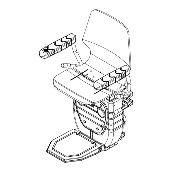
- Page 1 INSTALLATION Infinity Stairlift Rail Carriage MANUAL Seat Huddersfield • England...
- Page 2 INTRODUCTION The information contained within this manual has been designed for use by Bespoke approved engineers who have received the appropriate product training in the following categories, 1. Product installation. 2. Testing and commissioning. lt is also assumed that the person...
- Page 3 CONTENTS Introduction 2 Contents 3 Rail Preparation and Fixing 4-9 Carriage Preparation and Assembly 10-30 Calibrate and Program the Stairlift 31-35 Troubleshooting 36-39 Wiring Diagrams 40 Certificate of Conformity 41 Demonstration and Handover 42 Installation Tools 43...
- Page 4 RAIL PREPARATION Remove packaging and protective wrapping from rail sections. Position rail sections on staircase as per Stairlift Specifications 2108.8 Model BS 101 Installation Drawing. Type Base/Stanchion Base Stanchion Type Total Height Right Number Height Length Handing 205 ABF 312.87 Swivel Manual 499.87...
- Page 5 RAIL PREPARATION Thread 2-core cable through lower tube of each section of rail, working from top to bottom. Ensure a minimum of 150mm of cable at each end.
- Page 6 RAIL FIXING Assemble rail joints together working from bottom to top of stairs. Note: Offer top tubes first. Apply grease to male part of joint. Pins should be flush with stair side of rail. Fit and tighten joint clamps Using the installation drawing details: Check top and bottom rail heights over the corresponding steps.
- Page 7 RAIL FIXING Secure plates to the staircase by the following method: Loosen grub screws on leg collar Fix foot-plate with 3 screws (Figure 4) Tighten screw to leg. Repeat for each leg. The following fixings are recommended: Timber Staircase - 3 x 50mm screws. Concrete Staircase -3 x 50mm screws &...
- Page 8 RAIL FIXING Finally ensure all rail dimensions are in accordance with the rail installation drawing. Carry out any final adjustment to the bases as required using the 3 x Grub Screws then tighten once the rail position is correct.
- Page 9 MOUNTING THE CHARGER Find a suitable power supply as close as possible to either the top or bottom of the stairs. Mount the charger in a suitable position near the power supply using the screws supplied. Please ensure the charger is mounted level and secure.
- Page 10 CARRIAGE PREPARATION...
- Page 11 CARRIAGE PREPARATION First unpack all the pre-assembled units from their packaging, taking care not to place the carriage on the floor, avoiding damage. Your carriage will arrive already pre-assembled as either a manual swivel option or powered swivel option as per your order.
- Page 12 CARRIAGE ASSEMBLY Fig 1 INSTALLING THE BATTERIES To install the batteries first remove the front panel by unscrewing the 4 main screws. Once you’re have inserted the batteries consult figure 2, making sure the battery circuit is correct. Fig 2 FUSE...
- Page 13 CARRIAGE PREPARATION LOADING ONTO THE RAIL Next insert the long loading bar into the top skate of the carriage and insert the Loading strap small cone stopper in the bottom rail tube. Fig 1 At the top of the stairs lift the carriage Loading Bar with the loading strap and insert the loading bar into the top rail tube, slowly...
- Page 14 CARRIAGE ASSEMBLY CONNECT THE SEAT BASE WITH ARMS TO THE CARRIAGE You can now begin to install the seat to the carriage. First, lift the seat above the carriage and feed the joystick cable down through the hole located in the seat boss plate, before lowering the seat down onto the plate ensure to feed all the cable through when doing so, to prevent...
- Page 15 CARRIAGE ASSEMBLY Now line the holes up on the seat frame 2x Long Screws down to the boss plate below. Fix with the 2 shorter bolts towards the front of the 2x Short Screws seat, the 2 longer ones to the back. Please ensure the correct screws are positioned in the correct holes as incorrect installation will result in damage.
- Page 16 RUNNING THE CHAIR ON Switch on the lift by pressing the orange switch on the front of the carriage to the on position. Remove the PCB cover for access to the programming buttons and to have a clearer view of the LCD screen. The lift should already come set up correctly ready for programming, but this can be checked by going through the menu...
- Page 17 RUNNING THE CHAIR ON The lift will not run unless in program mode or already programmed to the rail. To put the lift into Program mode, Press the scroll button until you see ‘POSITION’ (this is the first option you come to if scrolling from the home screen), then press and HOLD the scroll button and this will change to ‘Program LO 1500’...
- Page 18 INSTALL RAIL CHARGE POINTS Return to the rail and fit the charge points to both the top and bottom connecting the core cable at both ends, use the diagram in the installation guide to ensure correct polarity (+ to the lower charging strip and - to the top) once you are happy with the positions fasten the final end stop brackets at the top and bottom of the rail.
- Page 19 PROGRAMMING Below is breakdown and explanation of each of the menu options shown on the display when using the scroll / adjust button. The home screen will HAND show lift status, for example, ‘LIFT LEFT / RIGHT READY’ or OFF CHARGE’ before you scroll through the menu, the display will automatically go back to the This is to determine the hand of the lift...
- Page 20 PROGRAMMING SWIVEL TRAVEL MANUAL / POWERED QUIET / ALARM Option for the lift to BEEP when travelling up or This option is to set up whether the lift has a manual or powered swivel down the rail INT.CP LANGUAGE PASS / STOP SELECT LANGUAGE When the lift has an Intermediate Charging Point Choose 1 of 7 language options;...
- Page 21 PROGRAMMING TRIPS SPEED NO FUNCTION NO FUNCTION This logs how many the trips the lift has made This is used for factory assembly ONLY -this cannot be reset FAULT SOFTWARE LOGS VERSION RESET FAULT COUNT NO FUNCTION PRESS ON EACH FAULT The PCB will record each fault / safety switch Used to determine the current software version of ever activated on the unit.
- Page 22 PROGRAMMING Next, to program the Stairlift, put the lift into Program mode and begin to run it down the bottom charge point, making sure the charger is turned on before making contact, If you have an intermediate charge point, turn the charger on when you are below this so that the bottom charge point is the first in Position...
- Page 23 PROGRAMMING The ‘LO’ shown on the screen is the speed the lift will travel after programming, press the adjust button to change to ‘HI’ to program the lift to full speed, the speed can be changed at any point on the lift as you travel up to the top charge point by pressing the adjust button again to select between ‘HI’...
- Page 24 PROGRAMMING THE BEND SLOWING FUNCTION (Optional) Note: To program using the slowing function The Infinity 4.Press ‘Adjust’ Stairlift must be programmed using following the steps; to move to ‘HI’ 1. Once Programmed as described on pages 19-21 2. Move off the first charge point 3.
- Page 25 PROGRAMMING Now begin to drive the lift up to the next charge point, where the lift will again stop by itself when it detects the charge point, if this is an intermediate drive the lift up again until you reach the top. Once the lift has stopped on the last charging point, press and hold the scroll button again until ‘POSITION’...
- Page 26 REMOTE CONTROL The remotes will already come pre- programmed to the lift, should you need to program them, turn the lift off/on again, then within the first 5 minutes of the lift being switched back on, press and hold all 3 buttons on the remote control for 3 HOLD seconds, repeat the process again for any additional remote controls, The remotes...
- Page 27 TROUBLESHOOTING & SAFETY Here we are going to quickly check the stopping safety features. First move the Stairlift to a convenient position, now run the Stairlift placing you hand in front of each sensor individually running the lift both up and down the rails. Front Back...
- Page 28 MANUAL OVERRIDE Manually insert the winding handle into the hole located on the left side of the carriage and locate the winding mechanism. Engage the winding mechanism and manually turn the handle. To release the over-speed governor (OSG) wind the stairlift in the upwards direction to release the OSG arm.
- Page 29 RESET THE OSG Run the lift upwards with the manual override, the OSG should come loose from the tube then. Make sure that the OSG is in neutral position again. The unit does not need re-programming DETAIL A SCALE 1 : 2...
- Page 30 THE DISPLAY DIAGNOSTICS FOOTREST The Display diagnostics feature that can inform the engineer of CHARGE LEFT/RIGHT any problems that The Infinity Stairlift has encountered during installation or in general use. Lift not charging Footrest safety Depending on the problem The •Check lift is parked on a...
- Page 31 THE DISPLAY DIAGNOSTICS S E A T BOTT.SKA top.SKA Left/right LEFT/RIGHT LEFT/RIGHT Main chassis safety Bottom skate safety Top skate safety switch activated switch activated switch activated •Check for obstructions and •Check for obstructions and •Check for obstructions and covers able to move freely covers able to move freely covers able to move freely •Check Mainframe wiring loom...
- Page 32 THE DISPLAY DIAGNOSTICS S E A T R.M.U. Over S WI V E L Fault Speed Seat swivel safety switch R.M.U reed switch is not Over speed switch is activated •Check O.S.G assembly is in activated (will also show when receiving a signal •Check white OSG roller neutral position, if not reset...
- Page 33 THE DISPLAY DIAGNOSTICS FAULTS NOT SHOWN ON DISPLAY Board has no power, but LED 1 is activated O v e r Relay •There is a live short on a safety line, un plug each connector on C u r r e nt Fault the PCB until the light goes out, this will determine which loom the...
- Page 34 INFINITY WIRING DIAGRAM Mainswitch Groundbattery Black Battery Positive 30A Fuse Chargingpoint Brown Brown Swivelsensor Swivelsensor Mainframe Mainframe_2 Safety Right Safety Left Connect to Blue swivelsensor Orange Orange Blue Green Joystick Green Mainframe Joystick left Black Black nr.2 Extension armrest LED Ground sensor Black nr.3...
- Page 36 DEMONSTRATION AND HANDOVER • DEMONSTRATION On N0 occasion should the manual override function allow the user to • EXPLANATION swivel the chair in • USER SAFETY the down direction. • USER BOOKLET 8) Ask the user to sit comfortably on the •...
- Page 37 TOOLS AND EQUIPMENT INSTALLATION TOOLS 19) Magnetic angle finder 1) 2 ft (500mm) spirit level (approx) 2) Extension Bar 3/B” or W drive) 20) Digital Multi meter/Clamp meter 3) Tape Measure ~ 5 metres (must be capable of measuring DC 4) 6mm twist drill bit (15/16”) current at 30A for at least 5 seconds) 21) Nut runners - sizes: 5mm, 5) 8mm masonry drill bits...
- Page 38 Infinity Stairlift Rail Carriage Seat Huddersfield • England...
Need help?
Do you have a question about the Infinity and is the answer not in the manual?
Questions and answers