Advertisement
Oil Dispense Valve
Instruction Manual
WARNING:
Read carefully and understand all INSTRUCTIONS before operating. Failure
to follow the safety rules and other basic safety precautions may result in serious personal
injury.
Save these instructions in a safe place and on hand so that they can be read when required.
Keep these instructions to assist in future servicing.
REV 06/23/16
Advertisement
Table of Contents

Related Manuals for Lubeworks 1813351

Summary of Contents for Lubeworks 1813351
- Page 1 Oil Dispense Valve Instruction Manual WARNING: Read carefully and understand all INSTRUCTIONS before operating. Failure to follow the safety rules and other basic safety precautions may result in serious personal injury. Save these instructions in a safe place and on hand so that they can be read when required. Keep these instructions to assist in future servicing.
-
Page 2: General Safety Regulations
GENERAL SAFETY REGULATIONS WARNING: The warnings, cautions, and instructions discussed in this instruction manual cannot cover all possible conditions or situations that could occur. It must be understood by the operator that common sense and caution are factors that cannot be built into this product, but must be supplied by the operator. -
Page 3: Intended Use
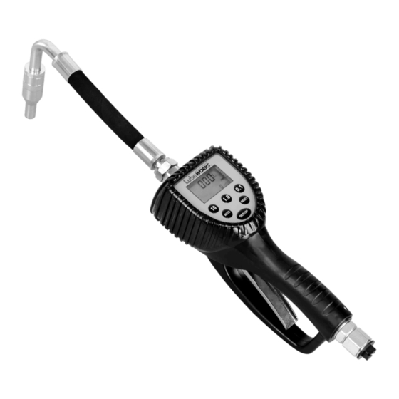
INTENDED USE Oil preset meter can be used to dispense motor oil. With the pre-selected function, the nozzle automatically closes the valve and stops dispensing. TECHNICAL DETAILS Item No. 1813351 Flow Range 0.3-9.2 GPM Operating Pressure Range 7-1000 PSI Operating Temperature Max. -
Page 4: Operation
OPERATION The Digital Meter requires 1 Alkaline cell 9V batteries to operate (batteries included). For battery replacement, refer to Section D, Battery Replacement elsewhere in this manual. 1. Keypad Buttons Press to enter the quantity to be dispensed. AUTO AUTO Press to enter and exit the AUTO Mode. -
Page 5: Operating The Meter
2. Insert zhe metal end of the hose into zhe swivel. Tigthen completely with an open ende adjustable wrench. NOTE:The threaded end of the meter always has female threads .the meter end of the hose must have male threads.apply thrad sealant, anaerobic adhesive or equivalents,to the male end .the inlet and outlet swvel connections are 1/2”... - Page 6 To access the various customizing functions and to select the desired options, two different actions are indicated on the keys. • This symbol indicates that it is necessary to press briefly, and afterwards release it. AUTO • This symbol indicates that it is necessary to press and hold on the key for a few OK/STOP seconds.
- Page 7 B-2. AUTO Mode Meter stores: AUTO 1-2-3-4-last: Five different PRESET values which are frequently used. Start up the Meter by selecting RESET Press as many times as necessary to AUTO To start dispensing, pull the trigger completely, then release. reach the desired values and the values are repeated.
- Page 8 B-3. User Mode B-4. Use The Trigger If the Meter is off, press to re-start it. RESET The value is last amount dispensed, the Meter will display: 5000 3087 TOTAL Stored Value Total To select a new PRESET value (for example, 12.3), press the numeric keys as many times as needed;...
- Page 9 C-2. Value Setting C-3. Unit Setting The Meter allows the Operator to store 5 The Meter allows the user to select one of different PRESET values (AUTO 1...AUTO the following measurement Units: 4), which can be recalled without having to •...
- Page 10 C-4. Decimal Digits Setting C-5. Reset Setting Press and hold three times to OK/STOP Press and hold OK/STOP four times to set set the function. the function. The Meter will display: The Meter displays: Blinking point Blinking 00.00 1see AUTO TOTAL When the number point is blinking, press AUTO...
- Page 11 Why calibrate? If the METER is used: • With fluids having a viscosity close to the limits of the allowed range (such as low-viscosity antifreeze fluids or high-viscosity oils for gear boxes). • In extreme flow rate conditions (close to the min. and max. value of the allowed range), it may be necessary to carry out an on-site calibration.
- Page 12 Press again to modify the value to After correction: AUTO Indicated value Real value equal the volume of the calibrated Blinking container. 6.90 6.95 Indicated value Real value Blinking 6.90 6.95 Meter Calibrated Container AUTO Press again, the Meter will Meter Calibrated Container calculate...
- Page 13 D. Battery replacement 9V DC battery is applied for power supply. When voltage is below 6.5V, screen of flowmeter will flash and the meter cannot be used any longer, which means battery must be replaced immediately. Batte ry replacement must be processed under dormancy mode after screen disappears for the sake of reliable setting preservation.
- Page 14 EXPLODED AND PARTS LIST 10 12 31 23 19 20...
-
Page 15: Troubleshooting Guide
Part No. Description Q’ty Part No. Q’ty Description Right cover Cross Recessed Pan Tapping Screw Meter Cover Washer flat Front Label left cover Flexible Spout Main Circuit Board Cross Recessed Pan Tapping Screw Filter Screw Seat Meter Holder Washer Body Spring Shaft Swivel... - Page 16 Size: 145x210mm 128克铜版纸 REV 06/23/16 2.09.05.30.361...
Need help?
Do you have a question about the 1813351 and is the answer not in the manual?
Questions and answers