
Related Manuals for Allen-Bradley AADvance T9110


Summary of Contents for Allen-Bradley AADvance T9110
- Page 1 Safety Manual Original Instructions AADvance Controller Catalog Numbers T9110 T9300 T9310 T9401/2 T9431/2 T9451 T9481/2...
- Page 2 Important User Information Read this document and the documents listed in the additional resources section about installation, configuration, and operation of this equipment before you install, configure, operate, or maintain this product. Users are required to familiarize themselves with installation and wiring instructions in addition to requirements of all applicable codes, laws, and standards.
- Page 3 Labels may also be on or inside the equipment to provide specific precautions. SHOCK HAZARD: Labels may be on or inside the equipment, for example, a drive or motor, to alert people that dangerous voltage may be present. BURN HAZARD: Labels may be on or inside the equipment, for example, a drive or motor, to alert people that surfaces may reach dangerous temperatures.
- Page 4 Rockwell Automation Publication ICSTT-RM446N-EN-P - April 2018...
- Page 5 Summary of Changes Issue Record This manual contains new and updated information as indicated in the following table. Issue Date Comments Jan 2009 First Issue April 2009 Reformat to match associated product user manuals Aug 2009 QA review updates Sept 2009 Release 1.1 for TUV approval Oct 2009 TUV approval release...
- Page 6 Summary of Changes Topic Page Correct title and hypertext link for PFH and PFD Data 21 & 86 Update Module Label Update to Fault Tolerant Input and High Demand Architecture 48 & 49 Update to SIL 3 Architecture Update to Fault Tolerant I/O Architecture 51 &...
- Page 7 Preface In no event will Rockwell Automation be responsible or liable for indirect or consequential damages resulting from the use or application of this equipment. The examples given in this manual are included solely for illustrative purposes. Because of the many variables and requirements related to any particular installation, Rockwell Automation does not assume responsibility or reliability for actual use based on the examples and diagrams.
- Page 8 Preface Select the Find Downloads option under Download. In the Product Search field enter "AADvance" and the AADvance option is displayed. Double click on the AADvance option and the latest version is shown. Select the latest version and download the latest version. AADVANCE RELEASE This technical manual applies to AADvance Controller Firmware Release: 1.40 and Workbench Toolkits: 1.4 and 2.1...
- Page 9 Preface built, tested, installed and commissioned, operated, maintained and decommissioned. It defines the requirements to be met during the life-cycle stages of safety-related systems design and commissioning so the safety objectives of the system are achieved during operation. There are requirements for quality systems, documentation and competency in this technical manual;...
- Page 10 Preface Rockwell Automation Publication ICSTT-RM446N-EN-P - April 2018...
-
Page 11: Table Of Contents
Table of Contents Chapter 1 Introduction Verification of the Safety Manual ....... 15 Competency . - Page 12 Table of Contents Functional Safety Assessment ........42 Safety Integrity Design.
- Page 13 Table of Contents Precautions for HART in a Safety System ....83 HART Pass-Through ........84 Actuator Configurations.
- Page 14 Table of Contents Safety Requirements Checklist......112 Engineering Checklists ........113 I/O Architecture Checklist.
-
Page 15: Verification Of The Safety Manual
Chapter Introduction This chapter provides an introduction to the AADvance Safety Manual and to the AADvance system. Verification of the Safety The AADvance system and the user Safety Manual are certified by an independent certification body to meet the requirements of IEC 61508 SIL 3. Manual Competency The achievement of functional safety requires the implementation of the safety... -
Page 16: Terminology
Chapter 1 Introduction Terminology Vocabulary and Conventions The terms certification and certified are used widely within this Manual, these terms refer principally to the functional safety certification of the AADvance system to IEC 61508 SIL 3 and other relevant standards. This Manual contains rules and recommendations: •... - Page 17 Introduction Chapter 1 requirements. The system can be used for safety implemented functions as well as applications that are non-safety but still critical to a business process. This controller offers you the ability to create a cost-effective system including but not limited to any of the following applications: •...
- Page 18 Chapter 1 Introduction 1. Fault tolerance may be implemented by configuring dual or triplicated modules for each module type. NOTE There is no provision for configuring triplicated output modules 2. AADvance digital output modules contain an element of redundancy and are therefore tolerant to some faults. Within each output module channel there are a pair of series switches that enable redundant behavior for de-energize to trip applications (output SIL 3);...
- Page 19 Introduction Chapter 1 equipment. However, certain consideration to the cabinet type must be applied when used in hazardous environments. A secure network communications protocol, developed by Rockwell Automation for the AADvance system, permits distributed control and safety using new or existing network infrastructure while ensuring the security and integrity of the data.
-
Page 20: Aadvance Features
Chapter 1 Introduction AADvance Features The AADvance system controls complex and often critical processes in real time — executing programs that accept external sensor signals, solving logic equations, performing calculations for continuous process control and generating external control signals. These user-defined application programs monitor and control real-world processes in the oil and gas, refining, rail transit, power generation and related industries across a wide range of control and safety applications. -
Page 21: Communication Port Security
Introduction Chapter 1 • Anti-virus software must be installed and be kept updated. IMPORTANT Firewalls have been known to affect the operation of the AADvance Discover utility so it may be necessary to temporary disable the Firewall when using this tool. •... -
Page 22: Associated Documents
Chapter 1 Introduction Protocol Port Number Availability Purpose 2010 Always available Discovery and configuration protocol (DCP, Rockwell Automation) 2222 When configured CIP Produce & Consume IO 5000 When at least one P2P Trusted peer-to-peer subnet is active on a controller 44818 Always available CIP Producer &... -
Page 23: Controller Certification
Introduction Chapter 1 Document Title EN 50156-1:2004 Electrical equipment for furnaces and ancillary equipment: Requirements for application design and installation EN 54-2:1997,A1:2006 Fire alarm control panels UL 508 Industrial control equipment NOTE A good understanding of health and safety practices, functional safety principles is highly recommended;... -
Page 24: Environment Standards
Chapter 1 Introduction CAUTION: AADvance modules are suitable for use in Class I, Division 2, Groups A, B, C and D Hazardous locations or Non-hazardous locations only or equivalent. ATTENTION: Pour les modules AADvance sont utilisables dans Class I, Division 2, A, B, C et D pour un environnement dangereux ou pour un environnement non dangereux ou équivalente Environment Standards The AADvance system has been investigated to United States National... -
Page 25: Non-Hazardous Installation Requirements
Introduction Chapter 1 Listed Accessories for use with PLCs: • 9100 Processor Backplane • 9300 I/O Backplane • 9801 Digital Input Termination Assembly, Simplex • 9802 Digital Input Termination Assembly, Dual • 9803 Digital Input Termination Assembly, TMR; 9831 Analogue input Termination Assembly, Simplex •... -
Page 26: Installation Requirements For Hazardous Environment
Chapter 1 Introduction • Pollution Degree 4: Continuous conductivity occurs due to conductive dust, rain or other wet conditions. Installation Requirements The AADvance controller has been investigated and approved by UL for use as Industrial Control Equipment in hazardous locations, Class I, Division 2, for Hazardous Environment Groups A, B, C and D in North America. - Page 27 Introduction Chapter 1 File Number E251761 The AADvance controller investigation and approval is contained in the following file certifications: • NRAG.E251761: Programmable Controllers for Use in Hazardous Locations Class I, Division 2, Groups A, B, C and D. The products have been investigated using requirements contained in the following standards: •...
-
Page 28: Environments
Chapter 1 Introduction Certifications for Safety ATEX Certificate System Applications in Hazardous Environments TYPE EXAMINATION CERTIFICATE Equipment or Protective System intended for use in Potentially Explosive Atmospheres Directive 94/9/EC DEMKO 11 ATEX 1129711X Type Examination Certificate Number: Rev. 3 Programmable Logic Controllers Models 9110 Processor, 9111 Processor, 9401 Digital Input, Equipment: 9402 Digital Input, 9431 Analog Input, 9432 Analog Input, 9451 Digital Output, 9481 Analog Output, 9482... - Page 29 Introduction Chapter 1 Schedule [13] TYPE EXAMINATION CERTIFICATE No. [14] DEMKO 11 ATEX 1129711X Rev. 3 Report: 4786831849 [15] Description of Equipment: These devices are low-power, open-type programmable logic controllers that are intended for installation in an ultimate enclosure. The 9000 Programmable Logic Controller Series consist of the following Models: Model Description...
- Page 30 Chapter 1 Introduction Schedule [13] TYPE EXAMINATION CERTIFICATE No. [14] DEMKO 11 ATEX 1129711X Rev. 3 Report: 4786831849 Voltage(Vdc) Current (mA) 9831 18-32 0-24 9832 18-32 0-24 9833 0-32 9851 18-32 9852 18-32 9892 18-32 9881 18-32 0-24 9882 18-32 0-24 Routine tests None...
-
Page 31: Iecex Ul Certificate
Introduction Chapter 1 IECEx UL Certificate IECEx Certificate of Conformity INTERNATIONAL ELECTROTECHNICAL COMMISSION IEC Certification Scheme for Explosive Atmospheres for rules and details of the IECEx Scheme visit www.iecex.com Certificate No.: IECEx UL 12.0032X issue No.:2 Certificate history: Issue No. 2 (2014-5-28) Issue No. - Page 32 Chapter 1 Introduction IECEx Certificate of Conformity Certificate No.: IECEx UL 12.0032X Date of Issue: 2014-05-28 Issue No.: 2 Page 2 of 4 Rockwell Automation Ltd. Manufacturer: Hall Road, Maldon CM9 4LA United Kingdom Additional Manufacturing location (s): This certificate is issued as verification that a sample(s), representative of production, was assessed and tested and found to comply with the IEC Standard list below and that the manufacturer's quality system, relating to the Ex products covered by this certificate, was assessed and found to comply with the IECEx Quality system requirements.
- Page 33 Introduction Chapter 1 IECEx Certificate of Conformity Certificate No.: IECEx UL 12.0032X Date of Issue: 2014-05-28 Issue No.: 2 Page 3 of 4 Schedule EQUIPMENT: Equipment and systems covered by this certificate are as follows: These devices are low-power, open-type programmable logic controllers that are intended for installation in an ultimate enclosure.
- Page 34 Chapter 1 Introduction IECEx Certificate of Conformity Certificate No.: IECEx UL 12.0032X Date of Issue: 2014-05-28 Issue No.: 2 Page 4 of 4 DETAILS OF CERTIFICATE CHANGES (for issues 1 and above): Issue 1: Addition of Model 9892 and updated drawings. Issue 2: Update to the latest edition of IEC 60079-0 Annex: Annexe for IECEx UL 12.0032 Issue 2.pdf...
- Page 35 Introduction Chapter 1 Annexe for IECEx UL 12.0032 Backplane Ratings Model Description Voltage Current (mA) Input/Output Ratings (Vdc) 9100 Processor Backplane 18-32 10.4A (400mA per slot) 9101 Dual Processor Backplane 18-32 10.4A (400mA per slot) 9300 I/O Backplane 18-32 9.6A (400mA per slot) 9110 Processor Module...
-
Page 36: Module Labels
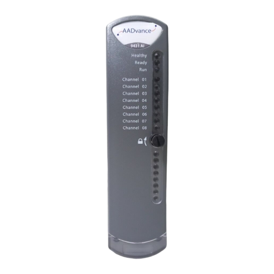
Chapter 1 Introduction Module Labels Labels containing comprehensive safety information are attached to all modules. The following CPU label is illustrated as an example, but similar labels are produced for each module type. KCC-EMC Registration Rockwell Automation Publication ICSTT-RM446N-EN-P - April 2018... -
Page 37: Functional Safety Management
Chapter Functional Safety Management This chapter explains the principles that should be applied to managing the safety related system. The Safety Management A prerequisite for the achievement of functional safety is the creation and use of procedures and other measures as part of a safety lifecycle, collectively System known as a Safety Management System. -
Page 38: Scope Definition
Chapter 2 Functional Safety Management • System engineering • Application programming • System production • System integration • System installation and commissioning • Safety system validation • Operation and maintenance plan • System modification • Decommissioning The definition of each life-cycle stage shall include its inputs, outputs and verification activities. -
Page 39: System Functional And Safety Requirements
Functional Safety Management Chapter 2 System Functional and Safety Requirements A set of system functions and their timing requirements will be specified. Where possible, the functions should be allocated to defined modes of operation of the process. For each function, it will be necessary to identify the process interfaces. -
Page 40: Application Programming
Chapter 2 Functional Safety Management If the possibility of errors cannot be eliminated, the system integrator should make sure that procedural methods are devised and applied to detect them. The system design should include facilities to allow field maintenance tasks can be performed. -
Page 41: System Integration
Functional Safety Management Chapter 2 hazardous area, power, earthing and EMC conditions. In many cases, there will not be a single installation environment. Elements of the system may be installed in differing locations; in these cases, it is important to know the environment for each location. -
Page 42: Operation And Maintenance Plan
Chapter 2 Functional Safety Management The validation shall confirm that each functional safety requirement has been implemented at the specified safety integrity level, and that the realization of the function achieves its performance criteria, specifically that the process safety time requirements have been met. The validation shall also consider the potential external common cause failures (power sources and environmental conditions) and ensure that the system will provide fail-safe operation when these conditions exceeded its design... -
Page 43: Safety Integrity Design
Functional Safety Management Chapter 2 The FSA is to be carried out by an audit team that shall include at least one senior competent person independent from the project. The FSA shall review the work associated with all applicable phases of the life-cycle to ensure that the requirements have been met and the processes followed appropriately. - Page 44 Chapter 2 Functional Safety Management Rockwell Automation Publication ICSTT-RM446N-EN-P - April 2018...
-
Page 45: Aadvance System Architectures
Chapter AADvance System Architectures An AADvance controller can be configured to manage non-safety up to SIL 3 safety related system requirements and low demand or high demand fault tolerant applications. This chapter describes the different system architectures that can be configured for an AADvance controller to meet this variety of requirements. -
Page 46: Fault Tolerant Input Architectures
Chapter 3 AADvance System Architectures Table 4 - Modules for SIL 2 Fail-Safe Architecture Position Module Type I/P A T9401/2 Digital Input Module, 24V dc, 8/16 Channel + T9801 Digital Input TA, 16 Channel, Simplex. T9431/2 Analogue Input Module, 8/16 Channel + T9831 Analogue Input TA, 16 Channel, Simplex T9300 I/O Base Unit CPU A... -
Page 47: Output Architecture
AADvance System Architectures Chapter 3 Table 5 - Modules for SIL 2 Architecture Position Module Type I/P A and B 2 × T9401/2 Digital Input Module, 24V dc, 8/16 Channel + T9802 Digital Input TA, 16 Channel, Dual 2 × T9431/2 Analogue Input Module, 8/16 Channel, Isolated, + T9832 Analogue Input TA, 16 Channel, Dual T9300 I/O Base Unit CPU A... -
Page 48: Fault Tolerant Input And High Demand Architecture
Chapter 3 AADvance System Architectures Digital Output For Digital Output Modules the following applies: • For energize to action high demand applications you must use dual digital output modules. Analogue Output For Analogue Output the Following applies: • The fail-safe state current of the Analogue Output module is less than 2mA. - Page 49 AADvance System Architectures Chapter 3 module failure due to a dangerous fault has not been replaced within the MTTR. WARNING: For High Demand mode applications you must use a minimum of a dual processor configuration. High demand energize to action applications will require dual output modules.
-
Page 50: Sil 3 Architectures
Chapter 3 AADvance System Architectures SIL 3 Architectures SIL 3 architectures have at least two processor modules and are suitable for use with: • SIL 3 de-energize to trip applications. • SIL 3 energize to action applications which have dual digital/analogue output modules. -
Page 51: Digital Output Modules
AADvance System Architectures Chapter 3 Digital Output Modules • For de-energize to action operation one digital output module is sufficient for SIL 3 requirements. However, for energize to action operation, dual digital output modules are required. • A digital output module fault must be repaired within the MTTR which was used in the PFD calculation. - Page 52 Chapter 3 AADvance System Architectures module failure due to a dangerous fault has not been replaced within the MTTR. WARNING: For SIL 3 applications you must use a minimum of a dual processor configuration. Digital Output Modules A digital output module fault must be repaired within the MTTR which was used in the PFD calculation.
-
Page 53: Tmr Input And Processor, Fault Tolerant Output
AADvance System Architectures Chapter 3 TMR Input and Processor, Fault Tolerant Output A SIL 3 TMR architecture offers the highest level of fault tolerance for an AADvance controller and consists of triple input modules, triple processors and dual output modules. •... -
Page 54: Certified Configurations
Chapter 3 AADvance System Architectures Table 10 - Modules for TMR Input and Processor, Fault Tolerant Output Position Module Type I/P A 3 × T9401/2 Digital Input Module, 24V dc, 8/16 Channel + T9803 Digital Input TA, 16 Channel, TMR 3 ×... - Page 55 AADvance System Architectures Chapter 3 Table 13 - Output Modules Modules Certified Conditions Configuration Digital Outputs 1oo1, 1oo2 or 1oo2D De-energize to action (normally energized): SIL 3 with 1 or 2 modules fitted. (1oo2D with dual output modules fitted). T8451, 24V dc, 8 channel.
-
Page 56: Internal Diagnostics
Chapter 3 AADvance System Architectures Table 14 - Auxiliary Modules Modules Conditions Processor Base Safety-related and can be used for safety critical applications in Fault tolerant/High demand SIL 2 applications with 2 modules fitted or SIL 3 applications with 2 or 3 modules fitted. T9100 I/O Base Safety-related and can be used for safety critical applications in SIL 3. -
Page 57: Safety Networks
AADvance System Architectures Chapter 3 Safety Networks AADvance provides two safety network functionality that will allow data exchanges across a SIL 3 rated safety communication across the Ethernet communications link: • SNCP (Safety Network Control Protocol) • Peer-to-Peer (not supported by Workbench 2.0) SNCP Safety Networks SNCP (Safety Network Control Protocol) is the Safety Protocol that allows elements of an AADvance System to exchange data. -
Page 58: Configuring Variable Bindings
Chapter 3 AADvance System Architectures The SNCP protocol can be configured in the AADvance controller to provide a safety network; refer to the AADvance Configuration Guide(s) (Publication Nos. ICSTT-RM405-EN-P & ICSTT-RM458-EN-P) for detailed configuration procedures. WARNING: For SNCP bindings to be used in a Simplex Network configuration, SIL 3 can be achieved but the following conditions must be met: •... - Page 59 AADvance System Architectures Chapter 3 continues using its last state value. Once disconnected the consumer attempts to re-establish a connection to the producer by sending a connection request at ConnectTimeout intervals. The consumer continues to send connection requests until a connection is established. The configuration also includes a timeout value for a consumer BindRespTimeout value for the binding data response from a producer.
-
Page 60: Peer-To-Peer
Chapter 3 AADvance System Architectures Peer-to-Peer WARNING: Peer-to-Peer functionality cannot be used in conjunction with AADvance Workbench 2.0, and is therefore not available for use in a safety related system. However, Peer-to-Peer functionality is available for AADvance Workbench 2.1 toolkit and subsequent revisions to be used in safety related systems. - Page 61 AADvance System Architectures Chapter 3 next and all slaves in turn. Finally the master transmits its own data then repeats the cycle with the slaves. Rockwell Automation Publication ICSTT-RM446N-EN-P - April 2018...
- Page 62 Chapter 3 AADvance System Architectures Safety Related Peer-to-Peer Configurations The following Peer-to-Peer configurations are approved for use in a safety Related Function: Table 15 - Safety Related Peer-to-Peer Configurations Peer-to-Peer Settings Certified Configuration Conditions Software Board Definitions: Certified for use over a single Certified as safety-related and can be used for communication network or safety critical communications in SIL 3...
-
Page 63: Aadvance Functional Safety System Implementation
Chapter AADvance Functional Safety System Implementation This chapter provides the implementation guidelines for an AADvance safety related system. General Design Measures for I/O Modules Functional Safety The AADvance system supports single module configurations, where it is acceptable to either stop the system or allow the signals corresponding to that module to change to their default fail-safe state. - Page 64 Chapter 4 AADvance Functional Safety System Implementation presence of a fault during this period, the system will continue to be able to respond when configured in a fault tolerant arrangement. ATTENTION: When a channel is not capable of reporting a value within the safety accuracy specified for the module, 'safe' values are reported instead.
-
Page 65: Energize To Action Configurations
AADvance Functional Safety System Implementation Chapter 4 Energize to Action Configurations Certain applications may require energize to action for inputs and/or outputs. ATTENTION: Energize to action configurations shall only be used if the following restrictions apply: • At least two independent power sources must be used. These power sources must provide emergency power for a safe process shutdown or a time span required by the application. - Page 66 Chapter 4 AADvance Functional Safety System Implementation • Sensor delay: 250ms • Time for actuator (an ESD valve) to fully operate: 1750ms In this example therefore, the setting of PST for the controller should be less than or equal to 3000ms. Choosing Controller PST Settings The response time allocated to a logic solver such as the AADvance controller needs to take account of delays within the operation of sensors and actuators.
-
Page 67: Industrial Functional Safety Standards
AADvance Functional Safety System Implementation Chapter 4 Industrial Functional Safety AADvance is designed to meet the following industrial safety system requirements: Standards NFPA 85 Requirements NFPA 85:2015 provides minimum requirements for the design, installation, operation and maintenance of large commercial industrial boilers, heat recovery, heat recovery steam generators and related combustion systems. -
Page 68: Nfpa 87 Requirements
Chapter 4 AADvance Functional Safety System Implementation The systems should be integrated in accordance with NFPA 86. In particular the following shall be applied. • The supplier of the application software for the AADvance controller shall provide both the end user and the safety authority having jurisdiction with the documentation needed to verify that all related safety devices and safety logic are functional before the controller is placed in operation. -
Page 69: En 50156
AADvance Functional Safety System Implementation Chapter 4 • Logic sequences or devices intended to cause a safety shutdown, once initiated, shall require operator action prior to resuming operation of the effected heating system plant. • Any changes to hardware or software shall be documented, approved, and maintained in a file on the site. -
Page 70: Bs En 54 Requirements
Chapter 4 AADvance Functional Safety System Implementation BS EN 54 Requirements BS EN 54-21997, A1:2006 specifies the requirements for control and indicating equipment for fire detection and fire alarm systems installed in buildings. The AADvance system is certified for use with BS EN 54 compliant systems. -
Page 71: En 54 Section 7.12 Alarm Signal Dependencies
AADvance Functional Safety System Implementation Chapter 4 • A system fault shall be audibly indicated. This indication may be capable of being silenced. • The cabinet of the control and indicating equipment shall be of robust construction, consistent with the method of installation recommended in the documentation. - Page 72 Chapter 4 AADvance Functional Safety System Implementation • the first alarm state shall be indicated by means of: • an audible indication as in 12.10 which may be the same as that in the fire alarm condition or fault warning condition; •...
-
Page 73: Field Configurations
AADvance Functional Safety System Implementation Chapter 4 • This approach to classifying hazardous locations is used by the United States (National Electrical Code), Canada (Canadian Electrical Code), Europe (CENELEC EN 60079-10) and throughout the world (IEC 60079-10). • While hazards are associated with all of these conditions, areas are only considered hazardous (classified) locations under definitions defined by the NEC, CEC, IEC 60079-10, or CENELEC EN 60079-10, as applicable. -
Page 74: Digital Input Field Loop Circuits
Chapter 4 AADvance Functional Safety System Implementation Digital Input Field Loop Circuits Recommended Field Loop Circuits This section contains recommended field loop circuits for line monitoring digital inputs used in Emergency Shutdown or Fire & Gas applications. Field Loop Circuit for Digital Input Field Loop Circuit for Line Monitored Digital Input for Emergency Shutdown Systems (ESD) The suggested values for R1 and R2 are as follows: R1 = 15K ... - Page 75 AADvance Functional Safety System Implementation Chapter 4 Suggested threshold values for both of the above circuits are as follows: Threshold ID Value (mV) Maximum Allowed 32000 SHORT CIRCUIT Threshold 8 19000 Threshold 7 18500 ON (nominal 16V) Threshold 6 11000 Threshold 5 10500 INDETERMINATE...
-
Page 76: Recommended Field Circuit For Digital Outputs
Chapter 4 AADvance Functional Safety System Implementation Field Loop Circuit for Line Monitored Digital Input for Fire and Gas Systems (F & G) • The F&G circuit will also allow two devices to be in alarm without reporting short circuit. •... -
Page 77: Analogue Input Field Loop Circuits
AADvance Functional Safety System Implementation Chapter 4 The field power input fuses are 5 A / 125 V, Slow Blow and comply to UL 248 - 14. NOTE 1. Alternatively instead of fitting two 5A fuses you can use Class 2 power supplies for the +24V dc field voltage. - Page 78 Chapter 4 AADvance Functional Safety System Implementation Field Loop Circuit for 2-Wire Analogue Input Field Loop Circuit for 3-Wire Analogue Input Rockwell Automation Publication ICSTT-RM446N-EN-P - April 2018...
-
Page 79: Recommended Circuit For Analogue Outputs
AADvance Functional Safety System Implementation Chapter 4 Field Loop Circuit for 4-Wire Analogue Input Recommended Circuit for Analogue Outputs These circuits are suitable for simplex and dual configurations of analogue output modules. All channels are isolated from each other but may be bridged at the '+' terminal if fed by a common system mounted supply. - Page 80 Chapter 4 AADvance Functional Safety System Implementation System powered devices Rockwell Automation Publication ICSTT-RM446N-EN-P - April 2018...
- Page 81 AADvance Functional Safety System Implementation Chapter 4 The above circuit is appropriate for devices that are powered by the system. The channel will pass a requested current between 0mA and 24mA. The field device could also be connected between the 24V supply and the Loop Plus terminal.
-
Page 82: Field Powered Devices
Chapter 4 AADvance Functional Safety System Implementation Field powered devices The above circuit is appropriate for devices that are powered locally and expect a current-controlled signal loop. Ensure that the loop is wired to pass current to the Loop Plus terminal and return it on the Loop Minus terminal. Sensor Configurations ATTENTION: In safety critical input applications using a single sensor, it is important that the sensor failure modes be predictable and well understood,... -
Page 83: Hart
AADvance Functional Safety System Implementation Chapter 4 power failure will lead to the fail-safe reaction. As with the allocation of signals to modules, there may be related functions (for example start and stop signals) where loss of field power should be considered in the same manner as the signal allocation. -
Page 84: Hart Pass-Through
Chapter 4 AADvance Functional Safety System Implementation ATTENTION: HART Pass-Through should be disabled if the field devices do not have locked configuration, or if the device status is not monitored and alarmed to prevent accidental or unauthorized changes to field device configuration. -
Page 85: Calculations Of Probability Of Failure Upon Demand
AADvance Functional Safety System Implementation Chapter 4 capability do not result in either an inability to respond to safety demands or in inadvertent operation. In some cases, this will require that channels be allocated on the same module, to ensure that a module failure results in the associated signals failing-safe. However, in most cases, it will be necessary to separate the signals across modules. -
Page 86: Reaction To Faults In The Processor Module
Chapter 4 AADvance Functional Safety System Implementation • diagnostics, fault indications and degradation of input modules • initiating diagnostics, fault declaration and for some fault conditions the degradation of output modules • recovery mode operation Reaction to faults in the processor module The processor module reports faults by front panel indicators and fault codes stored in the System Event log. -
Page 87: Processor Module Locking Screw Safety Function
AADvance Functional Safety System Implementation Chapter 4 Processor Module Locking Screw safety Function The module locking screw acts as a module retaining device and also as a switch that controls the module's operation. For the module to be fully operational the locking screw must be turned to the locked position. If the screw is turned to the unlocked position when a module is operational it will initiate a fault indication and the module will become non-operational. -
Page 88: I/O Module Process Safety Time (Pst)
Chapter 4 AADvance Functional Safety System Implementation When the first I/O module is installed and the locking screw set to the lock position, the startup and education process begins automatically. When the locking screw is set to the unlocked position then the module will switch off and the following indications will be displayed: Status Indicator Colors... -
Page 89: Reactions To Faults In The Input Modules
AADvance Functional Safety System Implementation Chapter 4 The input module can be configured to operate in SIL 2 or SIL 3 configurations for energize to action and de-energize to trip applications. The module provides the following isolation: • channel to channel galvanic isolation •... -
Page 90: Input Module Safety Accuracy
Chapter 4 AADvance Functional Safety System Implementation Input Module Safety Accuracy The input modules determine the channel state and the line fault state by comparing the input reported values with user programmed threshold values. When triple analogue input modules are used and active, the system adopts the median value. -
Page 91: Output Module Safety Functions
AADvance Functional Safety System Implementation Chapter 4 Output Module Safety Digital Output Module Safety Functions Functions The digital output module is rated at SIL 3 as a fail-safe module. In dual redundant configurations it can be used for energize to action and de-energize to trip SIL 3 applications. - Page 92 Chapter 4 AADvance Functional Safety System Implementation runs beyond this time period without receiving any updates, it enters the Shutdown Mode. Shutdown Mode When in the Shutdown mode the Ready and Run indicators will go RED. You can configure the state of the outputs when the module is in the Shutdown Mode.
-
Page 93: Analogue Output Module Safety Features
AADvance Functional Safety System Implementation Chapter 4 DO Termination assembly The DO termination assembly is safety critical, it comes in two sizes — simplex or dual. It has fuses for field output power and 8 field termination connections for the output signals. Analogue Output Module Safety Features Analogue Output Module Safety Applications The Analogue Output Module can be used in the following safety related... -
Page 94: Input And Output Forcing
Chapter 4 AADvance Functional Safety System Implementation Shutdown When in the Shutdown mode the Ready and Run indicators will go RED. You can configure the state of the outputs when the module is in the Shutdown Mode. You have to decide when you configure the module how you want the output channels to behave in the Shutdown mode. -
Page 95: Maintenance Overrides
AADvance Functional Safety System Implementation Chapter 4 for safety-related inputs and outputs should be implemented using the application program instead. The Force LED on the front of the T9110 Processor Module indicates when one or more I/O points are forced. The application program can determine how many points are currently forced;... -
Page 96: Application Program Development
Chapter 4 AADvance Functional Safety System Implementation Application Program The application program development shall follow a structured approach as defined in the AADvance Workbench documentation. Development ATTENTION: Development of application software consisting of programs (POUs), User Defined Functions and user Defined Function Blocks must follow the requirements defined in IEC 61511 (ANSI ISA-84.00.01) for LVL languages and the requirements defined in IEC 61508 for FVL languages. -
Page 97: Sequential Function Chart
AADvance Functional Safety System Implementation Chapter 4 • Safety Related • Function Block (FB) • Instruction List (IL) (not supported by Workbench 2.0) • Structured Text (ST) • Ladder Diagrams (LD) • Sequential Function Chart (SFC) (not supported by Workbench 2.0 in a safety related application) Safety Related Languages The AADvance controller supports a comprehensive set of certified functions. - Page 98 Chapter 4 AADvance Functional Safety System Implementation Burner flame supervision including temperature and air/gas pressure monitoring • Burner gas-to-air ratio control/supervision • Parts or whole of the start-up sequence of a batch reactor The fewer the number of inputs, outputs and signal paths, the fewer the number of permutations that require testing.
-
Page 99: Compiler Verification Tool Safety Requirement
AADvance Functional Safety System Implementation Chapter 4 The identification of safety functions is, in part, dependent on the specific safety philosophy. Examples of non-safety may include status indication, data reporting and sequence of events. It is important to establish that these elements are not safety related. -
Page 100: Communications Interaction
Chapter 4 AADvance Functional Safety System Implementation produced by the AADvance Workbench confirms that there are no errors introduced by the Compiler during the development of the application. To achieve this CVT decompiles the application project file and then compares each individual application project (POU) source files with its decomposed version. -
Page 101: Remote Fault Reset
AADvance Functional Safety System Implementation Chapter 4 Remote Fault Reset The AADvance controller offers the ability to remotely initiate a processor fault reset or standby join. These operations would normally require use of the processor Fault Reset button. The remote reset feature is enabled and configured as part of the application. -
Page 102: On-Line Modification
Chapter 4 AADvance Functional Safety System Implementation The scenarios should include possible plant conditions, sequences of plant conditions, and system conditions including partial power conditions, module removal and fault conditions. Where it is not possible to define a representative suite of test cases, all permutations of input conditions, i.e. -
Page 103: Physical Installation
AADvance Functional Safety System Implementation Chapter 4 Although these modifications will not affect the system's operation until the system configuration and application program have been modified, caution shall be exercised to ensure that the modifications do not affect other safety related functions. -
Page 104: Environmental Requirements
Chapter 4 AADvance Functional Safety System Implementation Environmental Requirements ATTENTION: HEAT DISSIPATION AND ENCLOSURE POSITION System and field power consumption by modules and termination assemblies is dissipated as heat. You should consider this heat dissipation on the design and positioning of your enclosure; e.g. enclosures exposed to continuous sunlight will have a higher internal temperature that could affect the operating temperature of the modules. -
Page 105: Electromagnetic Immunity And Emissions
AADvance Functional Safety System Implementation Chapter 4 Attribute Value Shock 15g peak, 11ms duration, ½ sine Altitude Operating 0 to 2000m (0 to 6,600 ft.) Storage and Transport 0 to 3000m (0 to 10,000 ft.) This equipment must not be transported in unpressurized aircraft flown above 10,000 ft. - Page 106 Chapter 4 AADvance Functional Safety System Implementation Standard Conditions Notes BS EN 61000-4-3:2006 10V rms/m (unmodulated) 80MHz- The equipment additionally complies with 2GHz: 80% 1 kHz AM fail-safe performance criteria at increased + A1:2008 levels of 20V/m over the range 80MHz to 1Hz Pulse Modulation 50:50 duty 1GHz and 3V rms/m (unmodulated) over cycle.
-
Page 107: Fit Emc Static Protection Covers
AADvance Functional Safety System Implementation Chapter 4 Marine Certification AADvance has been tested and found to comply with the EMC requirements of BS EN 60945:2002. EMC compliance within a marine environment is dependent on and can only be assured by the use of: •... - Page 108 Chapter 4 AADvance Functional Safety System Implementation The controller must be supplied with system power from a power source that complies with SELV and PELV standards. SELV (safety extra-low voltage) is a voltage which does not exceed 30 Vrms, 42.4 Vpeak and 60 Vdc between conductors, or between each conductor and earth in a circuit which is isolated from the line voltage by a safety transformer.
-
Page 109: System Security
AADvance Functional Safety System Implementation Chapter 4 System Security An AADvance system, with its workstations and DCS interfaces, whether using Ethernet networks or Serial links is likely part of a larger corporate network which may expose the system to accidental or malicious infection, attack or less obvious security vulnerabilities. - Page 110 Chapter 4 AADvance Functional Safety System Implementation Rockwell Automation Publication ICSTT-RM446N-EN-P - April 2018...
-
Page 111: Checklists
Chapter Checklists This chapter contains a number of example checklists. These are provided as an aid for competent engineers. In general each checklist item should result in "yes", where this is not the case a justification should be produced. Pre-Engineering Checklists The checklists provided within this section are applicable to the requirements. -
Page 112: Functional Requirements Checklist
Chapter 5 Checklists Functional Requirements Checklist Description Yes/No Is the definition of each of the required functions complete? Are the interfaces, signals, and data associated with each function clearly identified? Where a 'tag referencing' scheme is used for these signals, has a summary description of the naming convention been provided to facilitate an understanding of the role of the signal? Have the performance requirements for each function, or collective functions, been defined? Have the operating modes of the EUC, process or plant been clearly defined? -
Page 113: Engineering Checklists
Checklists Chapter 5 Engineering Checklists I/O Architecture Checklist Description Yes/No Has the PST been specified? What is the PST? Has the fault detection time for the system been specified? What is the fault detection time? Is the safety-accuracy adequate for the application? Where the fault detection time is greater than the PST, does the safety-related I/O configuration provide a fail-safe configuration? Note: If not, the system topology shall be discussed with the client to ensure that the system... -
Page 114: Override Requirements Checklist
Chapter 5 Checklists Override Requirements Checklist Description Yes/No Are the effects of overriding fully understood, particularly where the override action will affect independent parts of an application? Has a method of enabling, or more importantly removing, the overrides for the system as whole, or individual sub-systems, been provided? Have programming or procedural measures been defined to ensure that no more than a single override may be applied to a given safety-related process unit? -
Page 115: Processor And Application Checklist
Checklists Chapter 5 Processor and Application Checklist Description Yes/No If bindings communications is used, are the timeouts set to a response time within the required PST? Have you dual/triple processor been configured for SIL 3 and high demand applications? Have you recommended shut down actions for single module configuration outside of the MTTR assumed for the PFD calculations? Has security protection been used to prevent unauthorized access to the application programs? Have full branch and data tests been carried out on IL and ST program flow functions? - Page 116 Chapter 5 Checklists Rockwell Automation Publication ICSTT-RM446N-EN-P - April 2018...
-
Page 117: Associated Aadvance Publications
Chapter Additional Resources Associated AADvance For more information about the AADvance system refer to the associated Rockwell Automation technical manuals shown in table below. Publications Resource Document Number Safety Manual ICSTT - RM446 System Build Manual ICSTT - RM448 Configuration Guide ICSTT - RM405 Configuration Guide ICSTT - RM458... -
Page 118: Regional Offices
Chapter 6 Additional Resources Publication Purpose and Scope Safety Manual This technical manual defines how to safely apply AADvance controllers for a Safety Instrumented Function. It sets out standards (which are mandatory) and makes recommendations to make sure that installations satisfy and maintain their required safety integrity level. -
Page 119: Glossary
Glossary Glossary of Terms accuracy The degree of conformity of a measure to a standard or a true value. See also 'resolution' . achievable safe state A safe state that is achievable. NOTE Sometimes, a safe state cannot be achieved. An example is a non- recoverable fault such as a voting element with a shorted switch and no means to bypass the effect of the short. -
Page 120: Rockwell Automation Publication Icstt-Rm446N-En-P - April
Glossary backplane clip A sprung, plastic device to hold together two adjacent AADvance base units. Part number 9904. Used in pairs. base unit One of two designs which form the supporting parts of an AADvance controller. See 'I/O base unit' and 'processor base unit' . bindings Bindings describe a "relationship"... - Page 121 Glossary CIP Common Industrial Protocol. A communications protocol, formally known as 'CIP over Ethernet/IP' , created by Rockwell Automation for the Logix controller family, and which is also supported by the AADvance controller. AADvance controllers use the protocol to exchange data with Logix controllers.
- Page 122 Glossary cross reference Information calculated by the AADvance Workbench relating to the dictionary of variables and where those variables are used in a project. data access (DA) An OPC data type that provides real-time data from AADvance controllers to OPC clients. de-energize to action A safety instrumented function circuit where the devices are energized under normal operation.
- Page 123 Glossary fail operational state A state in which the fault has been masked. See 'fault tolerant' . fail safe The capability to go to a pre-determined safe state in the event of a specific malfunction. fault reset button The momentary action push switch located on the front panel of the 9110 processor module.
- Page 124 Glossary group A collection of two or three input modules (or two output modules), arranged together to provide enhanced availability for their respective input or output channels. hand-held equipment Equipment which is intended to be held in one hand while being operated with the other hand.
- Page 125 Glossary IEC 61511 An international standard for functional safety and safety instrumented systems (SIS) for the process industry, encompassing electrical, electronic and programmable electronic systems, hardware and software aspects. indicator A device which can change its state to give information. input (Workbench variable) In the context of an AADvance Workbench variable, this term describes a quantity passed to the Workbench from a controller.
- Page 126 Glossary manual call point A component of a fire detection and fire alarm system which is used for the manual initiation of an alarm. MODBUS An industry standard communications protocol developed by Modicon. Used to communicate with external devices such as distributed control systems or operator interfaces.
- Page 127 Glossary peer to peer A Peer to Peer network consists of one or more Ethernet networks connecting together a series of AADvance and/or Trusted controllers to enable application data to be passed between them. pinging In MODBUS communications, sending the diagnostic Query Data command over a link and by receiving a reply ensuring that the link is healthy and the controller is able to communicate with the master.
- Page 128 Glossary PST Process Safety Time. The process safety time for the equipment under control (denoted PSTEUC) is the period a dangerous condition can exist before a hazardous event occurs without a safety system as a protection. real A class of analogue variable stored in a floating, single-precision 32-bit format. redundancy The use of two or more devices, each carrying out the same function, to improve reliability or availability.
- Page 129 Glossary SFF Safe Failure Fraction. Given by (the sum of the rate of safe failures plus the rate of detected dangerous failures) divided by (the sum of the rate of safe failures plus the rate of detected and undetected dangerous failures). SIF Safety Instrumented Function.
- Page 130 Glossary termination assembly A printed circuit board which connects field wiring to an input or output module. The circuit includes fuses for field circuits. The board carries screw terminals to connect field wiring to the controller, and the whole assembly clips onto the 9300 I/O base unit.
- Page 131 How Are We Doing? form at http://literature.rockwellautomation.com/idc/groups/literature/documents/du/ra-du002_-en-e.pdf. Rockwell Automation maintains current product environmental information on its website at http://www.rockwellautomation.com/rockwellautomation/about-us/sustainability-ethics/product-environmental-compliance.page. Allen-Bradley, Rockwell Software, and Rockwell Automation are trademarks of Rockwell Automation, Inc. Trademarks not belonging to Rockwell Automation are property of their respective companies.
Need help?
Do you have a question about the AADvance T9110 and is the answer not in the manual?
Questions and answers