
Related Manuals for Micropack FDS303


Summary of Contents for Micropack FDS303
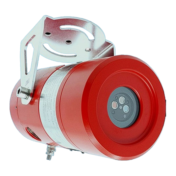
- Page 1 FDS303 MULTI SPECTRUM IR FLAME DETECTOR SAFETY & TECHNICAL MANUAL Ref: 3303.0001 micropackfireandgas.com...
-
Page 2: Table Of Contents
3.3.2 Relay Output 3.3.3 Internal Inter-connections Installation Checklist 3.4.1 Mechanical 3.4.2 Electrical System Design Guidelines Power Supply Cable Selection 4.2.1 DC Power This document is strictly private and confidential, reproduction without Micropack approval is prohibited. © Micropack Engineering Ltd, 2018... - Page 3 Appendix C Field of View Appendix D FM Approval Performance Report Appendix E Offshore Certification Appendix F IEC 61508 Failure Rate Data This document is strictly private and confidential, reproduction without Micropack approval is prohibited. © Micropack Engineering Ltd, 2018...
-
Page 4: Introduction
FDS303 can operate via a standard 3 or 4 wire termination • Microprocessor controlled heated optics increases resistance to moisture and ice. This document is strictly private and confidential, reproduction without Micropack approval is prohibited. © Micropack Engineering Ltd, 2018... -
Page 5: Safety Instructions
For European (ATEX) installations IEC/EN60079-14 ‘Electrical Installations in Hazardous Areas’ and ICE/EN60079-17 ‘Inspection and Maintenance in Hazardous Areas’ should be strictly observed. Multispectrum IR flame detector type FDS303 is to be installed in places where there is a low risk of mechanical damage. -
Page 6: Cautions
To prevent unwanted actuation or alarm, extinguishing devices must be inhibited/isolated prior to performance testing or maintenance. Detector Orientation Detectors should be mounted with the earth stud directly below the lens. This document is strictly private and confidential, reproduction without Micropack approval is prohibited. © Micropack Engineering Ltd, 2018... -
Page 7: En 54-Part 10 Limitation Of Use
The FDS303 is not approved for use in Oxygen-enriched atmospheres. As the FDS303 responds to flame. It cannot be used in locations where flare stacks are within its field of view or a reflected view is present without triggering alarms. -
Page 8: Installation
3303.8004, the rear enclosure cover Part Number 2301.6009, the enclosure body Part Number 2301.6007, certification rating label see above Part Number 3303.6006.01, and the mounting bracket Part Number 2301.6012. This document is strictly private and confidential, reproduction without Micropack approval is prohibited. © Micropack Engineering Ltd, 2018... -
Page 9: Mounting & Orientation
The mounting bracket allows the detector’s vertical orientation to be adjusted from 0 to 45° and allows a horizontal rotation of +/-45° when mounted from above. Figure 1: Detector Mounting Bracket This document is strictly private and confidential, reproduction without Micropack approval is prohibited. © Micropack Engineering Ltd, 2018... - Page 10 When mounting on a wall in this orientation allow for the cable gland and cable as this may restrict the downward rotation of the detector. This document is strictly private and confidential, reproduction without Micropack approval is prohibited. © Micropack Engineering Ltd, 2018...
-
Page 11: Wiring Procedure
• 0-20mA (source non-isolated) • Relay (Alarm & Fault) Listed below are wiring options dependent on the functional requirements of the detector. This document is strictly private and confidential, reproduction without Micropack approval is prohibited. © Micropack Engineering Ltd, 2018... -
Page 12: 0-20Ma Output
Over-range Note: The tolerance on the above outputs is +/- 0.3 mA dc current with a maximum loop resistance of 500 ohms This document is strictly private and confidential, reproduction without Micropack approval is prohibited. © Micropack Engineering Ltd, 2018... -
Page 13: Relay Output
NOTE: EOL and Alarm resistors values are defined by the client and the control system/fire panel which the detectors are being integrated into. This document is strictly private and confidential, reproduction without Micropack approval is prohibited. © Micropack Engineering Ltd, 2018... -
Page 14: Internal Inter-Connections
The following diagram shows the internal inter-connections of the alarm and fault relay contacts and jumpers. Each field connection is listed on this diagram for clarity. Figure 7: FDS303 Internal Inter-connections This document is strictly private and confidential, reproduction without Micropack approval is prohibited. © Micropack Engineering Ltd, 2018... -
Page 15: Installation Checklist
The gland should be torqued between 15 to 20 N m (11 to 15 lb·ft). This document is strictly private and confidential, reproduction without Micropack approval is prohibited. © Micropack Engineering Ltd, 2018... -
Page 16: Electrical
The enclosures external earth stud should be connected to a local earth point. Remove the transit plug(s) from the enclosure body gland entries. Fit approved cable glands. This document is strictly private and confidential, reproduction without Micropack approval is prohibited. © Micropack Engineering Ltd, 2018... -
Page 17: System Design Guidelines
Flame Detectors Length (m) with Length (m)with nominal supply 1.5mm2 2.5mm2 Conductors Conductors (12Ω/km) (7.6Ω/km) Detector 12W @ 24Vdc 500 Metres 780 Metres This document is strictly private and confidential, reproduction without Micropack approval is prohibited. © Micropack Engineering Ltd, 2018... - Page 18 Table 3: AWG Conversions Typical Conductor Resistance per km (3280 ft.) Cross Sectional Area (mm American Wire Gauge (AWG) DC Ω/km @ 20°C (Approx.) This document is strictly private and confidential, reproduction without Micropack approval is prohibited. © Micropack Engineering Ltd, 2018...
-
Page 19: Application Guidelines
All these issues are of crucial importance to a successful installation and they should be afforded great attention during the detailed design, construction and commissioning phases of the work. This document is strictly private and confidential, reproduction without Micropack approval is prohibited. © Micropack Engineering Ltd, 2018... -
Page 20: Detection Coverage
The detector can be factory configured with an alarm delay of up to 30 seconds. If this option is selected, however, it invalidates the SIL 2 and FM certification shown within this manual. This document is strictly private and confidential, reproduction without Micropack approval is prohibited. © Micropack Engineering Ltd, 2018... - Page 21 0.3m x 0.3m pan 60m (200 feet) JP4 Fire 0.3m x 0.3m pan 60m (200 feet) Methanol Fire 0.3m x 0.3m pan 42m (136 feet) This document is strictly private and confidential, reproduction without Micropack approval is prohibited. © Micropack Engineering Ltd, 2018...
-
Page 22: Maintenance And Commissioning
It is advisable to regularly review maintenance reports and adapt the maintenance period to the operating environment. This document is strictly private and confidential, reproduction without Micropack approval is prohibited. © Micropack Engineering Ltd, 2018... - Page 23 Isolate the power to the detector and ensure a fault is initiated within the control system. Check the Ma output is indicating 0mA. This document is strictly private and confidential, reproduction without Micropack approval is prohibited. © Micropack Engineering Ltd, 2018...
-
Page 24: Functional Testing
Micropack Engineering Repairs Ltd c/o Norcott Technologies Ltd Unit 1 Sunset Business Centre Widnes Cheshire WA8 0QR This document is strictly private and confidential, reproduction without Micropack approval is prohibited. © Micropack Engineering Ltd, 2018... -
Page 25: Fault Finding
Check the most obvious possible cause first. • Work systematically through the problem. • Keep good notes on the original problem, each step taken, and the results observed. This document is strictly private and confidential, reproduction without Micropack approval is prohibited. © Micropack Engineering Ltd, 2018... -
Page 26: Led Indication
The FDS303 is set to standard sensitivity (30 metres) Four yellow flashes at start up The FDS303 is set to high sensitivity (60 metres) This document is strictly private and confidential, reproduction without Micropack approval is prohibited. © Micropack Engineering Ltd, 2018... -
Page 27: Power Fault
When investigating power supply faults, it is important to check that all voltages are within the detectors operating range (18V to 32V) under full load conditions as the voltages measured under no load conditions can be misleading. This document is strictly private and confidential, reproduction without Micropack approval is prohibited. © Micropack Engineering Ltd, 2018... -
Page 28: Technical Specification
Support Fixings 2 x M8 Vertical Adjustment Degrees 0 to 45 Horizontal Adjustment Degrees Provided by support Axial (horizontal) Degrees +/- 45 Rotation This document is strictly private and confidential, reproduction without Micropack approval is prohibited. © Micropack Engineering Ltd, 2018... -
Page 29: Environmental Specification
Horizontal Field of View Degrees Vertical Field of View Degrees Detector Response Time Seconds Power on reset delay Seconds Optical Verification Default - on This document is strictly private and confidential, reproduction without Micropack approval is prohibited. © Micropack Engineering Ltd, 2018... -
Page 30: Appendix A Acronyms, Terms & Abbreviations
Nano Farad, Pico Farad – Capactiance Personal Computer (IBM PC Compatible) R or Ω Ohms (electrical resistance) Safe Failure Fraction Safety Integrity Level Voltage Versus Watts (Wattage) This document is strictly private and confidential, reproduction without Micropack approval is prohibited. © Micropack Engineering Ltd, 2018... -
Page 31: Appendix B Help Us To Help You
Please inform me of the outcome of this change: Yes/No For Micropack (Engineering) Limited: Action by: __________________________________________________________________Date: ______________________ R e s p o n s e : ________________________________________________________________Date: ______________________ This document is strictly private and confidential, reproduction without Micropack approval is prohibited. © Micropack Engineering Ltd, 2018... -
Page 32: Appendix C Field Of View
Vertical Field of view to a 0.1 m 2 N-heptane pan fire with an alarm response. 100%= 60 metres for High sensitivity. 100%= 30 metres for Standard sensitivity. 100%= 15 metres for Low sensitivity. This document is strictly private and confidential, reproduction without Micropack approval is prohibited. © Micropack Engineering Ltd, 2018... -
Page 33: Fm Approval Performance Report
15 metres Alarm 1500W electric heater modulated 1.8m 15 metres Alarm Reflected Sunlight 15 metres Alarm Reflected modulated Sunlight 15 metres Alarm This document is strictly private and confidential, reproduction without Micropack approval is prohibited. © Micropack Engineering Ltd, 2018... - Page 34 60 metres Alarm 1500W electric heater modulated 1.8m 60 metres Alarm Reflected Sunlight 60 metres Alarm Reflected modulated Sunlight 60 metres Alarm This document is strictly private and confidential, reproduction without Micropack approval is prohibited. © Micropack Engineering Ltd, 2018...
-
Page 35: Appendix E Offshore Certification
All locations with specified main areas compatibility Submerged application Enclosure Below floor plates in engine room All other locations Green areas show FDS303 approved location classes. This document is strictly private and confidential, reproduction without Micropack approval is prohibited. © Micropack Engineering Ltd, 2018... -
Page 36: Appendix Fiec 61508 Failure Rate Data
1547 Annunciation Undetected The FDS303 is classified as a Type B Element according to IEC 61508, having a hardware fault tolerance of 0. Therefore, based on the SFF of 94.83% a design can meet SIL 2 @ HFT=0 when the FDS303 is used as the only component in a SIF Sub-assembly. -
Page 37: This Document Is Strictly Private And Confidential, Reproduction Without Micropack Approval Is Prohibited. © Micropack Engineering Ltd
Doc Ref: 3303.0001 Rev 1.7 Tel: +1 832 431 3094 ISO 9001:2015 Certified Subject to modifications. © 2018 Micropack (Engineering) Ltd. www.micropackfireandgas.com Email: info@micropackamericas.com This document is strictly private and confidential, reproduction without Micropack approval is prohibited. © Micropack Engineering Ltd, 2018...
Need help?
Do you have a question about the FDS303 and is the answer not in the manual?
Questions and answers
Good day! Our FDS 303 has steady yellow light and fault indication on our FDS System. I already restarted it by switching off the 24VDC power supply, but nothing changes. What must be the fault of this sensor. Thank you
A steady yellow light on the Micropack FDS303 sensor indicates an internal fault. A red fault alarm is also present in this condition.
This answer is automatically generated
Can I do something about the fault or should the sensor be replaced?