Branson 2000X Series Instruction Manual
Hide thumbs
Also See for 2000X Series:
- Instruction manual (112 pages) ,
- Operation manual (180 pages) ,
- Operation manual (317 pages)
Table of Contents
Advertisement
Quick Links
2000X aed
Actuator
Instruction Manual
EDP 100-214-276
Software Version 10.xx and above
Rev. 3
BRANSON Ultrasonics Corporation
41 Eagle Road
Danbury, Connecticut 06813-1961 U.S.A.
(203) 796-0400
DOC EXPIRES 12PM 7/24/2012. Article or Material must comply with the requirements
stipulated by RoHS in its current version
Advertisement
Table of Contents

Related Manuals for Branson 2000X Series


Summary of Contents for Branson 2000X Series
- Page 1 Actuator Instruction Manual EDP 100-214-276 Software Version 10.xx and above Rev. 3 BRANSON Ultrasonics Corporation 41 Eagle Road Danbury, Connecticut 06813-1961 U.S.A. (203) 796-0400 DOC EXPIRES 12PM 7/24/2012. Article or Material must comply with the requirements stipulated by RoHS in its current version...
- Page 2 DOC EXPIRES 12PM 7/24/2012. Article or Material must comply with the requirements stipulated by RoHS in its current version...
- Page 3 Instruction Manual Manual Change Information At Branson, we strive to maintain our position as the leader in ultrasonics plastics joining, cleaning and related technologies by continually improving our circuits and components in our equipment. These improvements are incorporated as soon as they are developed and thoroughly tested.
- Page 4 Foreword Congratulations on your choice of a Branson Ultrasonics Corporation system! The Branson 2000X Series system is process equipment for the joining of plastic parts using ultrasonic energy. It is the newest generation of product using this sophisticated technology for a variety of customer applications.
-
Page 5: Table Of Contents
Warranty Statement, Disclaimer - - - - - - - - - - - - - - - - - 1 - 7 How to Contact Branson - - - - - - - - - - - - - - - - - - - - 1 - 10 1.4.1... - Page 6 Chapter 3: Delivery and Handling Shipping and Handling - - - - - - - - - - - - - - - - - - - - - -3 - 1 3.1.1 Environmental Specifications - - - - - - - - - - - - - - - - - -3 - 1 Receiving - - - - - - - - - - - - - - - - - - - - - - - - - - - - -3 - 2 Unpacking- - - - - - - - - - - - - - - - - - - - - - - - - - - - -3 - 3 3.3.1...
- Page 7 Installing the Stack in the Actuator - - - - - - - - - - - - - - 4 - 38 Mounting the Fixture on the Branson Base- - - - - - - - - - - 4 - 41 4.10 Testing the Installation - - - - - - - - - - - - - - - - - - - - - 4 - 42...
- Page 8 Chapter 7: Maintenance Calibration - - - - - - - - - - - - - - - - - - - - - - - - - - - -7 - 1 Periodic and Preventive Maintenance - - - - - - - - - - - - - -7 - 1 7.2.1 Periodically Clean the Equipment - - - - - - - - - - - - - - - -7 - 1 7.2.2...
- Page 9 2000X aed Actuator Instruction Manual List of Figures fig. 1.1 Safety label shown on the top of the 2000X aed Actuator- - - - - - - - - - - - - - - - 1-2 fig. 1.2 Connector label on the 2000X aed Actuator - - - - - - - - - - - - - - - - - - - - - - 1-3 fig.
- Page 10 4.24 Installing a 20kHz Stack in a Branson Actuator - - - - - - - - - - - - - - - - - - - - 4-38 fig. 4.25 Installing a 15kHz Stack in a Branson Actuator - - - - - - - - - - - - - - - - - - - - 4-39 fig.
- Page 11 1.2 Branson Contacts - - - - - - - - - - - - - - - - - - - - - - - - - - - - - - - - - 1-13 tab. 3.1 Environmental Specifications - - - - - - - - - - - - - - - - - - - - - - - - - - - -3-1 tab.
- Page 12 viii 100-214-276 Rev. 3 DOC EXPIRES 12PM 7/24/2012. Article or Material must comply with the requirements stipulated by RoHS in its current version...
- Page 13 Warranty Statement, Disclaimer - - - - - - - - - - - - - - - - - 1-7 How to Contact Branson - - - - - - - - - - - - - - - - - - - - -1-10 1.4.1...
-
Page 14: Safety Requirements And Warnings
Chapter 1: Safety and Support Safety Requirements and Warnings 1.1 Safety Requirements and Warnings 1.1.1 Symbols Found in this Manual Three symbols used throughout this manual warrant special attention: NOTICE A Note contains important information. It does not alert the user to potential injury, but only to a situation that might eventually require additional work or modification if you ignore it initially. - Page 15 2000X aed Actuator Chapter 1: Safety and Support Instruction Manual Safety Requirements and Warnings Figure 1.2 Connector label on the 2000X aed Actuator Figure 1.3 Caution label on the 2000X aed Actuator for the factory air supply Figure 1.4 Safety Labels on front of the 2000X aed Actuator CAUTION CRUSH PINCH WARNING 100-214-276 Rev.
-
Page 16: General Precautions
Chapter 1: Safety and Support General Precautions 1.2 General Precautions Take the following precautions before servicing the power supply: • Be sure the power switch is in the Off position before making any electrical connections. • To prevent the possibility of an electrical shock, always plug the power supply into a grounded power source. - Page 17 2000X aed Actuator Chapter 1: Safety and Support Instruction Manual General Precautions Manufacturers of Protective Materials and Equipment Hearing Protectors Safeware, Inc David Clark 9475 Lottsford Rd. 360 Franklin St. Suite 150 Box 15054 Largo, MD 20774-5351 Worcester, MA 01615-0054 www.safewareinc.com www.davidclark.com Softcomm Products...
-
Page 18: Intended Use Of The System
Section Chapter 4: Installation and Setup and in the 2000-series Installation Guide. 1.2.5 Regulatory Compliance The Branson 2000X aed actuator and converter receive their power and control from a 2000X- series power supply, and together make up a system. The 2000X power supply is designed for compliance with the following regulatory and agency standards: •... -
Page 19: Warranty Statement, Disclaimer
Sale, or contact your Branson representative. TERMS AND CONDITIONS OF SALE Branson Ultrasonics Corporation is herein referred to as the “Seller” and the customer or person or entity purchasing products (“Products”) from Seller is referred to as the “Buyer.” Buyer’s acceptance of the Products will manifest Buyer’s assent to these Terms and Conditions. - Page 20 Warranty Statement, Disclaimer ULTRASONIC JOINING EQUIPMENT NORTH AMERICAN WARRANTY POLICY Each product manufactured by Branson is guaranteed to be free from defects in material and workmanship for a period of time specified in Table 1 .1 Warranty Period from the date of invoice.
- Page 21 Repair service at the customer site • Includes parts and labor at the customer site performed by a Branson technician. The cus- tomer is responsible for all travel-related charges.
-
Page 22: How To Contact Branson
How to Contact Branson 1.4 How to Contact Branson Branson is here to help you. We appreciate your business and are interested in helping you suc- cessfully use our products. To contact Branson for help, use the following telephone numbers, or contact the field office nearest you. -
Page 23: Returning Equipment For Repair
Branson representative, or the shipment may be delayed or refused. If you are returning equipment to Branson for repair, you must first call the Repair department to obtain a Returned Goods Authorization (RGA) number. (If you request it, the repair depart- ment will fax a Returned Goods Authorization form to fill out and return with your equipment.) -
Page 24: Get An Rga Number
1.5.1 Get an RGA Number RGA# _____________ If you are returning equipment to Branson, please call the Repair Department to obtain a Returned Goods Authorization (RGA) number. (At your request, the Repair Department will fax an RGA form to fill out and return with the equipment.) 1.5.2 Record information about the Problem... -
Page 25: Departments To Contact
Chapter 1: Safety and Support Instruction Manual Returning Equipment for Repair 1.5.3 Departments to Contact Call your local Branson Representative, or contact Branson by calling, and asking for the appro- priate department as indicated in Table 1.2: Branson Contacts below. -
Page 26: Pack And Ship The Equipment
_______________________________________________________________________ _______________________________________________________________________ _______________________________________________________________________ 1.6 Obtaining Replacement Parts You can reach Branson Parts Store at the following telephone numbers: Branson Part Store direct telephone number: 877-330-0406 fax number: 877-330-0404 Many parts can be shipped the same day if ordered before 2:30 p.m., Eastern time. - Page 27 2000X aed Actuator Chapter 1: Safety and Support Instruction Manual Obtaining Replacement Parts For Your Notes 100-214-276 Rev. 3 1-15 DOC EXPIRES 12PM 7/24/2012. Article or Material must comply with the requirements stipulated by RoHS in its current version...
- Page 28 Chapter 1: Safety and Support Obtaining Replacement Parts 1-16 100-214-276 Rev. 3 DOC EXPIRES 12PM 7/24/2012. Article or Material must comply with the requirements stipulated by RoHS in its current version...
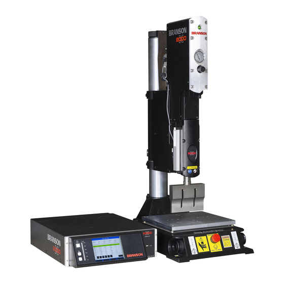
- Page 29 2000X distance Power Supply. 2.1 Models Covered This manual covers the Branson 2000X aed Actuator. The 2000X aed Actuator may be found in one of several configurations: • An Actuator on a Column Support, Column and Ergonomic Base, also called a Stand on Base (as seen on the following page) •...
-
Page 30: Introduction To The 2000X Aed Actuator Models Covered
Chapter 2: Introduction to the 2000X aed Actuator Models Covered Figure 2-1 shows a Branson 2000X aed Actuator mounted on a column support which, in turn is mounted on a column, and is supported by the ergonomic base. Figure 2.1... -
Page 31: Power Supply Manual Set
Left Side View of the 2000X aed 15kHz Actuator 2.1.1 Power Supply Manual Set The following documentation is available for the Branson 2000X-series Power Supplies that are compatible with the 2000X aed Actuator: • 2000X distance Power Supply Instruction Manual (EDP 100-412-167) •... -
Page 32: Features Of The System
The 2000X aed Actuator is designed with full, built-in pneumatic controls, and mechanical con- trols. Operation of the 2000X aed is controlled by inputs to the 2000X distance Power Supply. The pneumatics covered in this manual refer to the remote box package sold by Branson. Some customers may require custom controls. - Page 33 Features of the System • Amplitude Stepping: A patented Branson process, controlled by the Power Supply. At a specified time, energy, peak power, distance, or by external signal you can change the amplitude during the weld to control the flow of plastic. This feature helps ensure part consistency, higher strength parts and control of flash.
-
Page 34: Controls And Indicators
Chapter 2: Introduction to the 2000X aed Actuator Controls and Indicators • Encoder: Allows the power supply to monitor the distance the horn has travelled, enabling the use of distance functions. • Downspeed: Controls the rate of descent and force build-up on the part. •... -
Page 35: Welding Systems
Branson factory. The parameters of the individual presets can be modified by a Branson repre- sentative. Initally all 20 Presets are set to factory default. They are accessed via an RS232 link to the system controller. - Page 36 Chapter 2: Introduction to the 2000X aed Actuator Welding Systems Booster Success in ultrasonic assembly depends on the right amplitude of movement at the horn face. Amplitude is a function of horn shape, which is largely determined by the size and form of the parts to be assembled.
-
Page 37: Glossary Of Terms
Baud Rate: The rate of data transmission over the serial communication port. Beep: An audible signal produced by the Branson control board. Used to alert the operator to an unexpected condition. Cold Start: A condition that restores a setup to its default values. - Page 38 Chapter 2: Introduction to the 2000X aed Actuator Glossary of Terms Control Limits: Additional parameters that determine the end of the ultrasonic portion of the cycle and the move to the hold state. Converter: The device that converts electrical energy into mechanical vibrations at a high fre- quency (an ultrasonic rate).
- Page 39 2000X aed Actuator Chapter 2: Introduction to the 2000X aed Actuator Instruction Manual Glossary of Terms Main Menu: The list of categories of features available in the software, as displayed on the front panel of the Power Supply. Accessible by using a power supply front-panel button. Max Energy: Maximum Energy.
- Page 40 Chapter 2: Introduction to the 2000X aed Actuator Glossary of Terms Reject Limits: User-definable limits at which the violating cycle is identified as having pro- duced a bad part. Required: State used with limits indicating that a reset will be required when the limit is exceeded.
- Page 41 2000X aed Actuator Chapter 2: Introduction to the 2000X aed Actuator Instruction Manual Glossary of Terms -/+ S/R Trg D: The distance at which the trigger occurred. -/+ S/R Time: The weld time reached during the weld. Weld Count: Count of acceptable weld cycles. Weld Energy: The energy specified to be applied to the part during the weld cycle.
- Page 42 Chapter 2: Introduction to the 2000X aed Actuator Glossary of Terms 2-14 100-214-276 Rev. 3 DOC EXPIRES 12PM 7/24/2012. Article or Material must comply with the requirements stipulated by RoHS in its current version...
-
Page 43: Delivery And Handling Shipping And Handling
2000X aed Actuator Chapter 3: Delivery and Handling Instruction Manual Shipping and Handling Chapter 3: Delivery and Handling Shipping and Handling - - - - - - - - - - - - - - - - - - - - - - 3-1 3.1.1 Environmental Specifications - - - - - - - - - - - - - - - - - - 3-1 Receiving - - - - - - - - - - - - - - - - - - - - - - - - - - - - - 3-2... -
Page 44: Receiving
Chapter 3: Delivery and Handling Receiving 3.2 Receiving Branson Actuator units are carefully checked and packed before dispatch. It is recommended, however, that you follow the procedure below upon receiving your Actuator. Inspect the Actuator when it is delivered: Step:... -
Page 45: Unpacking
3.4 Returning Equipment If you are returning equipment to Branson Ultrasonic Corporation, please call your Customer Service Representative to receive approval to return goods to Branson. If you are returning equipment for repair refer to... - Page 46 Chapter 3: Delivery and Handling Returning Equipment 100-214-276 Rev. 3 DOC EXPIRES 12PM 7/24/2012. Article or Material must comply with the requirements stipulated by RoHS in its current version...
- Page 47 2000X aed Actuator Chapter 4: Installation and Setup Instruction Manual Chapter 4: Installation and Setup About Installation- - - - - - - - - - - - - - - - - - - - - - - - - 4-2 Handling and Unpacking - - - - - - - - - - - - - - - - - - - - - 4-2 4.2.1 Unpack the Power Supply - - - - - - - - - - - - - - - - - - - 4-3...
-
Page 48: Installation And Setup About Installation
Installing the Stack in the Actuator - - - - - - - - - - - - - - -4-38 Mounting the Fixture on the Branson Base- - - - - - - - - - - -4-41 4.10 Testing the Installation - - - - - - - - - - - - - - - - - - - - - -4-42 4.11 Still Need Help? - - - - - - - - - - - - - - - - - - - - - - - - - -4-43... -
Page 49: Unpack The Power Supply
The linear encoder (on the left side of the actuator) is very sensitive. Do not use the linear encoder assembly as a hand-hold, allow no impact on it, and do not place any weight on it. Depending on which one of the following options applies to you, unpack the Branson actuator assembly: 100-214-276 Rev. 3 DOC EXPIRES 12PM 7/24/2012. -
Page 50: Stand (Actuator On A Base)
Chapter 4: Installation and Setup Handling and Unpacking 4.2.3 Stand (actuator on a base) CAUTION Heed the “This End Up” arrows and the “Open Top First” instructions. The packaging is designed to be removed from the assemblies from an upright orientation only. Figure 4.2 Unpacking the Stand (Actuator on a Base);... - Page 51 2000X aed Actuator Chapter 4: Installation and Setup Instruction Manual Handling and Unpacking Figure 4.3 Unpacking the Stand (Actuator on a Base) and Left-side View of Stand of the 2000X aed 15kHz Actuator Move the shipping container close to the intended installation location, leave it on the floor. Open the top of the box.
-
Page 52: Stand (Actuator On A Hub)
Chapter 4: Installation and Setup Handling and Unpacking 4.2.4 Stand (Actuator on a Hub) Figure 4.4 Unpacking the Stand (Actuator on a Hub); Hub Shown Separately Booster Converter Note: Hubs may be lag-bolted to the Tool Kit Insert Box pallet for shipping purposes. 6-1/2in. -
Page 53: Actuator (Alone)
2000X aed Actuator Chapter 4: Installation and Setup Instruction Manual Take Inventory of Small Parts Remove the block(s) of wood between the base and the support by slowly loosening the two column clamps (allowing the stand to rise slightly) and then cutting the shipping tape on the block of wood. RETIGHTEN THE COLUMN CLAMPS. -
Page 54: Cables
Chapter 4: Installation and Setup Take Inventory of Small Parts 2000X Power Supply Actuator Part or Kit 15kHz 20kHz 30kHz 40kHz Stand (Base) Stand (Hub) (alone) 40kHz Sleeve ordered part ordered part ordered part 40kHz Sleeve Spanner ships w/ Sleeve ships w/ Sleeve ships w/ Sleeve Fixture Bolts and Washer M8 Allen Wrench... -
Page 55: Installation Requirements
(approximately 30-36 inches) with the operator sitting or standing in front of the system. Stands (on hubs) are often used in automated systems and may be manually or automatically loaded and unloaded. Actuators alone can be mounted in any orientation, Contact Branson if mounting upside down. WARNING The stand may tip over if moved around the axis of its column, if not properly secured. -
Page 56: Environmental Specifications
Chapter 4: Installation and Setup Installation Requirements 4.4.2 Environmental Specifications Table 4.3 Environmental Specifications Environmental Concern Acceptable Range Humidity 30% to 95%, non-condensing Ambient Operating Temperature +5°C to +50°C (41°F to 122°F) -25°C to +55°C (-13°F to +131°F); Storage / Shipping Temperature Up to +70°C (+158°F) for 24 hours 4.4.3 Electrical Input Power Ratings Plug the Power Supply into a single-phase, grounded, 3-wire, 50 or 60 Hz power source. -
Page 57: Air Cylinder Consumption
2000X aed Actuator Chapter 4: Installation and Setup Instruction Manual Installation Requirements 4.4.4 Air Cylinder Consumption Cubic Feet of air per minute per inch of stroke length (each direction) Pressure 1.5" 0.00174 0.00243 0.00312 0.00381 0.00450 0.00513 0.00590 0.00660 0.00730 0.00800 2"... - Page 58 Chapter 4: Installation and Setup Installation Requirements Figure 4.6 Power Supply Dimensional Drawing 5.0” (127mm) Desired Clearance Air Intake 20.6” 522.9mm Air outlet is under 3.53” front panel 89.7mm 0.45” 13.4” 11.4mm 340.1mm 17.55” 445.8mm 100 % 80 % 60 % 5.2”...
- Page 59 2000X aed Actuator Chapter 4: Installation and Setup Instruction Manual Installation Requirements Figure 4.7 2000X Actuator Dimensional Drawing SPACE ALLOCATION FOR CONNECTOR AND CABLE BENDS 18.59 472mm 5.00 9.82 127mm 250mm 13.52 343m m ENCODER FOR AED ONLY 16.70 machined mounting 242mm surfaces (3 places)** 43.0...
- Page 60 Chapter 4: Installation and Setup Installation Requirements Figure 4.8 2000X aed 15kHz Actuator Dimensional Drawing 4-14 100-214-276 Rev. 3 DOC EXPIRES 12PM 7/24/2012. Article or Material must comply with the requirements stipulated by RoHS in its current version...
- Page 61 2000X aed Actuator Chapter 4: Installation and Setup Instruction Manual Installation Requirements Figure 4.9 Block Wiring Diagram P73 J73 RF OUT RF RTN J75-A EXTLSSRC 24VRTN EXTLSSIG CONVERTER +24VSRC S_CLK+ J61-A CS_A/D+ ULSSRC VOLT(REG) CS_D/A+ CS_DIG+ ULSSIG 24VRTN 24VRTN ULS_SIG DGND E_STOP_SRC SV1SRC...
-
Page 62: Factory Air
Chapter 4: Installation and Setup Installation Requirements 4.4.5 Factory Air The factory compressed air supply must be “clean (to a 5 micron level), dry and unlubricated” air with a regulated maximum pressure of 100 psig (690 kPa). Depending on your application, the actuator requires between 35 to 100 psi. -
Page 63: Installation Steps
2000X aed Actuator Chapter 4: Installation and Setup Instruction Manual Installation Steps 4.5 Installation Steps WARNING This product is heavy and can cause a pinching or crushing injury during installation or adjust- ment. Keep clear of moving parts and do not loosen clamps unless directed to do so. CAUTION If a stand is not mounted in a vertical position, the air filter (on the column support) must be removed, reoriented, and replumbed. - Page 64 Chapter 4: Installation and Setup Installation Steps Figure 4.10 Base Mounting Centers 28.0 in / 711 mm 7.37 in / 187 mm 14.75 in / 16.5 in / 375 mm 419 mm Mounting Holes accept 3/8 inch or metric M10 cap screws 21.31 in / 541 mm Figure 4.11 Base Mounting Centers Dimensional Drawing for 2000X aed 15kHz Actuator...
-
Page 65: Mounting The Stand (Actuator On Hub-Mounted Column)
2000X aed Actuator Chapter 4: Installation and Setup Instruction Manual Installation Steps 4.5.2 Mounting the Stand (Actuator on Hub-mounted column) During unpacking, you removed the hub from the column/stand assembly. You must choose a mounting location for the hub that will support the column and actuator, and provide the hardware to mount it. Four mounting bolt holes are provided at the corners of the casting, and will accept your 3/8 inch or M10 hard- ware. -
Page 66: Actuator (Alone)
Chapter 4: Installation and Setup Installation Steps Connect factory air to the air hose on the stand (1/4 NPT male fitting on the hose). A quick-discon- nect fitting is suggested. Use a lockout device on the air line if required. Verify the base/start switch control cable is properly connected to the back of actuator. - Page 67 2000X aed Actuator Chapter 4: Installation and Setup Instruction Manual Installation Steps Figure 4.13 Rear view of Actuator, showing Mounting Surface, Bolt and Guide Pin locations M10 x 1.5 THDS 10 mm deep (3 places) 15.63 397 mm Machined mounting surfaces (3 places)** 14.30 363 mm...
-
Page 68: Mount The Power Supply
The cable lengths are limited based on the operating frequency of the welding system. Performance and results can suffer if the RF cable is crushed, pinched, damaged or modified. Contact your Branson Repre- sentative if you have special cable requirements. In some cases, remote operation from a User I/O or a Host Computer can be used to solve a distance limitation. -
Page 69: Input Power (Main)
RF Cable and the Actuator Interface cable. A 37-pin Actuator Interface Cable is used for Power and Control Signaling between the Power Supply and a Branson Actuator. The cable connects to the rear of the Power Supply and the rear of the Actuator. -
Page 70: Start Switch Connection (Automation)
Line Cord 4.5.8 Start Switch Connection (Automation) A Branson actuator requires two start switches and emergency stop connection. Stands on a base include this connection (factory installed and connected from the base) while the stand on a hub and actuator (alone) applications require the user make their own start switch/E-stop connections, as follows: Figure 4.17 Start Switch Connection Codes... -
Page 71: Serial (Rs-232) Port Connector
Refer to Note above. EMER STOP is an emergency stop switch, normally closed. NOTICE Refer to the Branson Automation Guide (EDP 100-214-273) for additional information about selection and use of Input and Output features. 4.5.9 Serial (RS-232) Port Connector An RS-232c serial port (DB-9 format) is provided for the Host Computer option. -
Page 72: User I/O Interface
1150 610C ** Includes both off the shelf and Branson supplied units. However, all units excepting the Branson supplied Okidata 520 may not stop printing when abort is selected in the menu. The data may have been transferred to the printer and can’t be halted. - Page 73 2000X aed Actuator Chapter 4: Installation and Setup Instruction Manual Installation Steps Table 4.6 User I/O Cable Pin Assignments. Signal Name Signal Type Direction Signal Range Definition Colors ACT_CLEAR Logic Output 0/24V, 100mA Actuator clear signal Red/Wht True AMPLITUDE_OUT Analog Output 0V to 10V Amplitude signal from PS...
- Page 74 NOTICE User can change 24V Logic 0 True to 1. NOTICE Refer to the Branson Automation Guide (EDP 100-214-273) for additional information about selection and use of Input and Output features listed in the following Table. 4-28 100-214-276 Rev. 3 DOC EXPIRES 12PM 7/24/2012.
-
Page 75: Input Power Plug
2000X aed Actuator Chapter 4: Installation and Setup Instruction Manual Installation Steps Table 4.7 User I/O Input and Output Function Selection Input Output J3_1_INPUT Disabled J3_8_OUTPUT Disabled Select Preset* Confirm Preset J3_17_INPUT J3_22_OUTPUT Ext U/S Delay Amplitude Decay J3_19_INPUT J3_36_OUTPUT Display Lock Ext Beeper J3_31_INPUT... -
Page 76: User I/O Dip Switch (Sw1)
In some configurations, it might be necessary to open the Power Supply and change the DIP (Dual In-line Package) switches on the power supply module. DIP switches change the Seek and Start functions and can affect the Amplitude Control functions. Refer to your Power Supply Instruction manual, or 2000X Series Installation Guide for detailed information. -
Page 77: Guards And Safety Equipment
The 2000X Series control system has been desingned to conmform to the safety requirements of NFPA 79, EN 60204-1 and CFR 1910.212. Two Hand Control of the 2000X Series control system has been designed to comply with Type 3 of NFPA, and Type III of EN 60204-1. -
Page 78: Rack Mount Installation
Chapter 4: Installation and Setup Rack Mount Installation 4.7 Rack Mount Installation If the system is Rack Mounted, you need to order the Rack Mount handle kit. The kit includes two rack mounting handles and two corner pieces, which support the handles and provide the rack mount interface. CAUTION The Rack Mount handle kit does NOT support the power supply in the rack. -
Page 79: Assemble The Acoustic Stack
2000X aed Actuator Chapter 4: Installation and Setup Instruction Manual Assemble the Acoustic Stack Step Procedure Order and obtain the Rack Mount kit for your Power Supply. The brackets in the Kit are designed for standard 19-inch rack mounting options. From the front corners of the Power Supply, remove the Front Corner bezels by removing the two Phillips screws. -
Page 80: For A 15 Khz System
Chapter 4: Installation and Setup Assemble the Acoustic Stack 4.8.1 For a 15 kHz System Step Action Clean the mating surfaces of the converter, booster, and horn. Remove any foreign material from the threaded holes. Install the threaded stud into the top of the booster. Torque to 450 in-lbs, 50.84Nm. -
Page 81: For A 30Khz System
2000X aed Actuator Chapter 4: Installation and Setup Instruction Manual Assemble the Acoustic Stack 4.8.3 For a 30kHz System Step Action Clean the mating surfaces of the converter, booster, and horn. Remove any foreign material from the threaded holes. Apply a drop of Loctite® 290 threadlocker (or equivalent) to the studs for the booster and horn Install the threaded stud into the top of the booster;... -
Page 82: Assembling The Acoustic Stack
Horn Vise Stack Assembly Torque Table NOTICE The use of a Branson torque wrench or the equivalent is recommended. P/N 101-063-787 for 15, 20, and 30kHz systems and 101-063-618 for 40kHz systems. Table 4.10 Stud Torque Values Used On Stud Size... -
Page 83: Connecting Tip To Horn
180 in.-lbs, 20.33 Nm. CAUTION The horn of 2000X 15kHz actuator is not excess of 30kg for ordinary application. If you have bigger horn application, please contact Branson for further assistance. 100-214-276 Rev. 3 4-37 DOC EXPIRES 12PM 7/24/2012. Article or Material must comply with the requirements... -
Page 84: Installing The Stack In The Actuator
Reinstall the door assembly, and start the four door screws. Align the horn by rotating it, if necessary. Torque the carriage door to20 in.-lbs to secure the stack. Figure 4.24 Installing a 20kHz Stack in a Branson Actuator Hex Screw... - Page 85 2000X aed Actuator Chapter 4: Installation and Setup Instruction Manual Assemble the Acoustic Stack Figure 4.25 Installing a 15kHz Stack in a Branson Actuator 100-214-276 Rev. 3 4-39 DOC EXPIRES 12PM 7/24/2012. Article or Material must comply with the requirements...
- Page 86 Reinstall the door assembly, and start the four door screws. Align the horn by rotating it, if necessary. Torque the carriage door to 20 in.-lbs to secure the stack. NOTICE Note: Branson recommends using the CA-30 converter instead of the CJ-30 converter with the sleeve assembly. 4-40 100-214-276 Rev.
-
Page 87: Mounting The Fixture On The Branson Base
Chapter 4: Installation and Setup Instruction Manual Mounting the Fixture on the Branson Base 4.9 Mounting the Fixture on the Branson Base (hardware and mounting holes) The base provides mounting holes for your fixture. Mounting holes are also provided for the optional Bran- son leveling plate kit. -
Page 88: Testing The Installation
Chapter 4: Installation and Setup Testing the Installation 4.10 Testing the Installation Turn on the air supply connections including the pneumatic dump valve and verify that the air pres- sure indicator light in the actuator is lit. Ensure there are no leaks in the air supply connections. Turn on the power supply. -
Page 89: Still Need Help
Still Need Help? 4.11 Still Need Help? Branson is pleased that you chose our product and we are here for you! If you need parts or technical assis- tance with your 2000X-series system, call your local Branson representative or contact Branson customer service by calling the appropriate department as indicated in Table 1.2 Branson... - Page 90 Chapter 4: Installation and Setup Still Need Help? 4-44 100-214-276 Rev. 3 DOC EXPIRES 12PM 7/24/2012. Article or Material must comply with the requirements stipulated by RoHS in its current version...
-
Page 91: Chapter 5: Technical Specifications Technical Specifications
2000X aed Actuator Chapter 5: Technical Specifications Instruction Manual Technical Specifications Chapter 5: Technical Specifications Technical Specifications - - - - - - - - - - - - - - - - - - - - - 5-1 5.1.1 Requirement Specifications - - - - - - - - - - - - - - - - - - - 5-1 5.1.2 Performance Specifications - - - - - - - - - - - - - - - - - - - 5-2... -
Page 92: Performance Specifications
Chapter 5: Technical Specifications Technical Specifications 5.1.2 Performance Specifications The following tables detail some of the performance specifications associated with the 2000X Actuator. Table 5.2 Maximum Welding Force (at 100 psig and 4.0” stroke) 1.5" cylinder 135 lb. / 61.4 k 2.0”... -
Page 93: Physical Description
2000X aed Actuator Chapter 5: Technical Specifications Instruction Manual Physical Description 5.2 Physical Description Refer to Chapter 4 for dimensional information. 5.2.1 Standard Items Actuator Support The actuator support is firmly clamped to the column. With the actuator support, you can adjust the height of actuator housing above the fixture position. - Page 94 Chapter 5: Technical Specifications Physical Description Mechanical Stop The mechanical stop limits the downward travel of the horn. To prevent equipment damage, adjust the stop so that the horn will not contact the fixture when no workpiece is in place. There is an indicator on the right side showing the position of the stop block.
- Page 95 2000X aed Actuator Chapter 5: Technical Specifications Instruction Manual Physical Description Figure 5.1 2000X Actuator Pneumatic System INPUT FILTER REGULATOR COOLING VALVE EXHAUST PRIMARY MAC VALVE CARRIAGE CYLINDER FLOW CONTROL VALVE 100-214-276 Rev. 3 DOC EXPIRES 12PM 7/24/2012. Article or Material must comply with the requirements stipulated by RoHS in its current version...
- Page 96 Chapter 5: Technical Specifications Physical Description S-Beam Load Cell and Dynamic Follow Through The S-Beam Load Cell measures the force being applied to the part to trigger ultrasonics and record the welding parameters. The S-Beam Load Cell assembly ensures that pressure is applied to the part prior to the application of ultrasonic energy.
-
Page 97: Chapter 6: Operation
2000X aed Actuator Chapter 6: Operation Instruction Manual Actuator Controls Chapter 6: Operation Actuator Controls - - - - - - - - - - - - - - - - - - - - - - - - - 6-1 Initial Actuator Settings - - - - - - - - - - - - - - - - - - - - - - 6-2 6.2.1 Regulated Air Pressure and Air Pressure Gauge - - - - - - - - 6-2... -
Page 98: Initial Actuator Settings
Supply manual for tuning, testing, setup, and operating instructions. WARNING When using larger horns, avoid situations where fingers could be pinched between the horn and the fixture. Contact Branson for information on an optional guard. 6.2 Initial Actuator Settings The Actuator is controlled by the Power Supply, however there are several functions that are part of the Actuator. -
Page 99: Factory Air Source
2000X aed Actuator Chapter 6: Operation Instruction Manual Initial Actuator Settings Initially, set the Regulator Knob to a counter-clockwise position, which is a low pressure setting. In the event something is incorrectly connected, a low air pressure setting will reduce any sudden movement. -
Page 100: Actuator Alignment And Height (Horn Travel)
Chapter 6: Operation Initial Actuator Settings 6.2.4 Actuator Alignment and Height (Horn travel) The horn carriage will travel up and down on the actuator’s slides. The actuator can also be adjusted up or down on the column. The distance between the fixture and horn should allow easy and ready access and removal of your parts. -
Page 101: Emergency Stop
If the Actuator is mounted on a Base, make sure that the Emergency Stop button is not pushed in. If not using the Branson Base, verify that the Emergency Stop signal source is not in the Emergency Stop mode. With a part in place, depress and hold both start switches simultaneously, or activate the start mechanism. - Page 102 Chapter 6: Operation Operating the Actuator Step: Action: The horn advances and contacts the part. Force develops between the horn and the part, activating the S-Beam Load Cell. Ultrasonic vibrations are activated. The power bar graph on the power supply indicates loading (usually in the 25% to 100% range).
-
Page 103: Calibration
FDA’s Good Manufacturing Practices, contact your Branson representative for additional information. 7.2 Periodic and Preventive Maintenance The following preventive measures will help ensure long term operation of your Branson 2000X Series Actuators. 7.2.1 Periodically Clean the Equipment Periodically disconnect the unit from power, remove the cover and vacuum out any accumulated dust and debris. -
Page 104: Recondition The Stack (Converter, Booster, And Horn)
Stack components function with greatest efficiency when the mating interface surfaces are in proper condition. For 15kHz, 20kHz and 30kHz products, a Branson Mylar washer should be installed between the horn and the booster, and booster and converter. Replace the washer if torn or perforated. - Page 105 (32.77 Nm). Torque 1/2-20 studs to 450 inch pounds (50.84 Nm).Torque M8x1-1/4 studs to 70 inch pounds (7.9 Nm). NOTICE The use of a Branson torque wrench or the equivalent is recommended. P/N 101- 063-617 for 20kHz systems and 101-063-618 for 40kHz systems. CAUTION Failure to follow torque specifications may cause the stud to loosen or break, and the system to overload.
-
Page 106: Routine Component Replacement
The lifetime of system pneumatic components is influenced by the quality of the compressed air provided. All Branson systems require clean, dry, (normal) factory compressed air. When oil or moisture is present in the compressed air, the lifetime of the pneumatic components will be reduced. -
Page 107: Parts Lists
2000X aed Actuator Chapter 7: Maintenance Instruction Manual Parts Lists 7.3 Parts Lists The following tables list the available Accessories and Parts for the 2000X aed Actuator (tables 7.2 and 7.3, respectively) and for the 2000X aed 15kHz Actuator (tables 7.4 and 7.5, respec- tively): Table 7.2 Accessories List for 2000X aed Actuator... - Page 108 Chapter 7: Maintenance Parts Lists Table 7.2 Accessories List for 2000X aed Actuator (Continued) Description EDP Number Hub, 2000X for 4” column 101-063-583 Support 4” black 100-246-1311 Column 4’, 4’’ OD x 1/4” wall 100-028-021 Column 4’, 4” OD x 1/2” wall (option) 100-028-011 Column 6’, 4”...
- Page 109 2000X aed Actuator Chapter 7: Maintenance Instruction Manual Parts Lists Table 7.2 Accessories List for 2000X aed Actuator (Continued) Description EDP Number Purple (Ti), Ratio 1:0.6 101-149-124 Boosters - 40kHz (Same as XL: 8 mm) Black (Ti), Ratio 1:2.5 101-149-084 Silver (Ti), Ratio 1:2.0 101-149-083 Gold (Ti), Ratio 1:1.5...
- Page 110 Downspeed Control Assembly (Flow Control 2 1/2 - 3" cyl) 100-246-1309 Interface Board Assembly 102-242-717R ULS Cable Assembly 100-241-181 Power Light Harness Assembly 100-246-924 Carriage 2000X Series 100-018-039 Assy Cylinder AED/AOD - 1.5” Diameter 100-246-859 Assy Cylinder AED/AOD - 2.0” Diameter 100-246-858 Assy Cylinder AED/AOD - 2.5” Diameter 100-246-576 Assy Cylinder AED/AOD - 3.0”...
- Page 111 2000X aed Actuator Chapter 7: Maintenance Instruction Manual Parts Lists Table 7.3 Spare Parts List for the 2000X Actuator (Continued) Description EDP Number Assy Regulator 100-246-553 Assy Gauge 100-246-554 Assy RF Conn 100-246-932 ULS Switch Optical 200-099-190 Table 7.4 Accessories List for 2000X aed 15kHz Actuator Description EDP Number 2000X aed 15kHz Actuator with 3.0-inch diameter cylinder...
- Page 112 Chapter 7: Maintenance Parts Lists Table 7.5 Spare Parts List for the 2000X aed 15kHz Actuator (Continued) Description EDP Number RF Harness Assembly 560-257-230R S-Beam Assembly 100-246-1276 Cooling Valve Assembly 100-246-896 Base Assembly 560-056-042R Act-support Assembly(China) 560-164-006R Act-support Assembly(Danbury) 149-246-1422 Solenoid Valve 100-246-901 Downspeed Control Assembly (Flow Control 1 1/2-2”...
- Page 113 2000X aed Actuator Chapter 7: Maintenance Instruction Manual Parts Lists Table 7.5 Spare Parts List for the 2000X aed 15kHz Actuator (Continued) Description EDP Number Assy Regulator 100-246-553 Assy Gauge 100-246-554 ULS Switch Optical 200-099-190 Rod Mech Stop 580-221-005R Block Mech Stop 580-081-060R Spring, Compression 890-048-030R...
- Page 114 Chapter 7: Maintenance Parts Lists Table 1-1: Suggested Spares (Continued) Assembly EDP # 1 - 4 Units 6 - 12 Units 14 + Units Lock Nut 100-073-188 Knob 100-064-054 Knob Set Screw 200-298-102 Pin, Clevis 200-078-146 Extension Spring 100-095-139 Eyebolt 200-298-027 Carriage 100-018-039...
- Page 115 2000X aed Actuator Instruction Manual Index Numerics 15kHz Stack Assembly - - - - - - - - - - - - - - - - - - - - - 4-34 About Installation - - - - - - - - - - - - - - - - - - - - - - - - 4-2 Actuator Base - - - - - - - - - - - - - - - - - - - - - - - - - - - - - 5-3 Slide Mechanism - - - - - - - - - - - - - - - - - - - - - - - 5-3...
- Page 116 Block Wiring Diagram - - - - - - - - - - - - - - - - - - - - - 4-15 Cables - - - - - - - - - - - - - - - - - - - - - - - - - - - - - - 4-8 Calibration - - - - - - - - - - - - - - - - - - - - - - - - - - - - 7-1 Connecting Tip to Horn - - - - - - - - - - - - - - - - - - - - - 4-37 Controls - - - - - - - - - - - - - - - - - - - - - - - - - - - - - 2-6...
- Page 117 Module Options DIP Switch - - - - - - - - - - - - - - - - - - - 4-30 Mounting the Fixture on the Branson Base - - - - - - - - - - - - 4-41...
- Page 118 Parallel Printer Connector - - - - - - - - - - - - - - - - - - - 4-25 Parts Lists - - - - - - - - - - - - - - - - - - - - - - - - - - - - 7-5 Accessories List - - - - - - - - - - - - - - - - - - - - - - - 7-5 Spare Parts - - - - - - - - - - - - - - - - - - - - - - - - - - 7-7 Periodic and Preventive Maintenance...
- Page 119 2000X aed Actuator Instruction Manual Safety Guards - - - - - - - - - - - - - - - - - - - - - - - - - - - - 4-31 PVC Materials - - - - - - - - - - - - - - - - - - - - - - - - 1-6 S-Beam Load Cell - - - - - - - - - - - - - - - - - - - - - - - - 2-6 Serial (RS-232) Port - - - - - - - - - - - - - - - - - - - - - - - 4-25 Serial port - - - - - - - - - - - - - - - - - - - - - - - - - - - - 4-25...
- Page 120 Unpack the Power Supply - - - - - - - - - - - - - - - - - - - - 4-3 Unpack the Stand or Actuator - - - - - - - - - - - - - - - - - - 4-3 Unpacking Actuator Assemblies - - - - - - - - - - - - - - - - - 3-3 Upper Limit Switch - - - - - - - - - - - - - - - - - - - - - - - - 5-3 User I/O Cable Pin Assignments - - - - - - - - - - - - - - - - 4-27...
Need help?
Do you have a question about the 2000X Series and is the answer not in the manual?
Questions and answers