Table of Contents
Advertisement
Quick Installation Guide
00825-0100-4051, Rev BA
June 2009
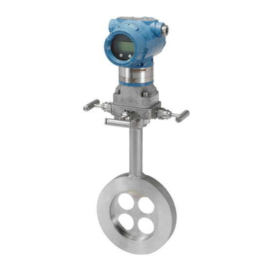
Rosemount 3051 Pressure Transmitter
Includes Transmitter Option TR
®
HART
¢00825-0100-4801J¤
www.rosemount.com
Step 1: Mount the Transmitter
Step 2: Consider Housing Rotation
Step 3: Set Switches
Step 4: Connect the Wiring and Power Up
Step 5: Verify Configuration
Step 6: Trim the Transmitter
Safety Instrumented Systems Requirements
Product Certifications
Start
End
Rosemount 3051
Advertisement
Table of Contents

Related Manuals for Rosemount 3051


Summary of Contents for Rosemount 3051
- Page 1 Quick Installation Guide 00825-0100-4051, Rev BA Rosemount 3051 June 2009 Rosemount 3051 Pressure Transmitter Includes Transmitter Option TR Start Step 1: Mount the Transmitter Step 2: Consider Housing Rotation Step 3: Set Switches Step 4: Connect the Wiring and Power Up...
-
Page 2: Important Notice
Quick Installation Guide 00825-0100-4051, Rev BA Rosemount 3051 June 2009 © 2009 Rosemount Inc. All rights reserved. All marks property of owner. Rosemount and the Rosemount logotype are registered trademarks of Rosemount Inc. Emerson Process Management Rosemount Emerson Process Management Division GmbH &... -
Page 3: Step 1: Mount The Transmitter
Quick Installation Guide 00825-0100-4051, Rev BA Rosemount 3051 June 2009 1: M OUNT THE RANSMITTER Liquid Flow Applications 1. Place taps to the side of the line. 2. Mount beside or below the taps. 3. Mount the transmitter so that the drain/vent valves are oriented upward. - Page 4 Quick Installation Guide 00825-0100-4051, Rev BA Rosemount 3051 June 2009 CONTINUED Panel Mount Pipe Mount ™ Coplanar Flange Traditional Flange In-line...
-
Page 5: Bolting Considerations
Quick Installation Guide 00825-0100-4051, Rev BA Rosemount 3051 June 2009 CONTINUED Bolting Considerations If the transmitter installation requires assembly of the process flanges, manifolds, or flange adapters, follow these assembly guidelines to ensure a tight seal for optimal performance characteristics of the transmitters. Use only bolts supplied with the transmitter or sold by Emerson as spare parts. -
Page 6: O-Rings With Flange Adapters
The two flange adapters are distinguished by unique O-ring grooves. Only use the O-ring that is designed for its specific flange adapter, as shown below. Rosemount 3051S / 3051 / 2051 / 3001 / 3095 Flange Adapter O-ring... -
Page 7: Inline Gage Transmitter Orientation
Quick Installation Guide 00825-0100-4051, Rev BA Rosemount 3051 June 2009 CONTINUED Inline Gage Transmitter Orientation The low side pressure port (atmospheric reference) on the inline gage transmitter is located in the neck of the transmitter, behind the housing. The vent path is 360° around the transmitter between the housing and sensor. -
Page 8: Step 4: Connect Wiring And Power Up
The figures below show the wiring connections necessary to power a 3051C/T and enable communications with a hand-held HART communicator. Transmitter Wiring (4-20 mA / HART) Power Supply 250 Installation of the transient protection terminal block does not provide transient protection unless the 3051 case is properly grounded. -
Page 9: Signal Wiring Grounding
Quick Installation Guide 00825-0100-4051, Rev BA Rosemount 3051 June 2009 CONTINUED Signal Wiring Grounding Do not run signal wiring in conduit or open trays with power wiring, or near heavy electrical equipment. Grounding terminations are provided on the outside of the sensor module and inside the Terminal Compartment. -
Page 10: Power Supply
Quick Installation Guide 00825-0100-4051, Rev BA Rosemount 3051 June 2009 CONTINUED Power Supply The dc power supply should provide power with less than two percent ripple. The total resistance load is the sum of the resistance of the signal leads and the load resistance of the controller, indicator, and related pieces. -
Page 11: Step 5: Verify Configuration
Quick Installation Guide 00825-0100-4051, Rev BA Rosemount 3051 June 2009 5: V ERIFY ONFIGURATION A check ( ) indicates the basic configuration parameters. At minimum, these parameters should be verified as part of the configuration and startup procedure. Table 1. HART Fast Key Sequence... -
Page 12: Step 6: Trim The Transmitter
If zero offset is greater than 3% of true zero, follow the “Using the Transmitter Zero Adjustment Button” instructions below to rerange. If hardware adjustments are not available, see the 3051 Reference Manual (document number 00809-0100-4051) to perform a rerange using the HART Communicator. -
Page 13: Safety Instrumented Systems
Process Management representative. 3051 Safety Certified Identification All 3051 transmitters must be identified as safety certified before installing into SIS systems. To identify a safety certified 3051, verify that QT is included in the transmitter model code. Installation No special installation is required in addition to the standard installation practices outlined in this document. - Page 14 Quick Installation Guide 00825-0100-4051, Rev BA Rosemount 3051 June 2009 Figure 8. Alarm Levels Rosemount Alarm Level Normal Operation 3.75 mA 4 mA 21.75 20 mA 3.9 mA 20.8 mA high saturation saturation Namur Alarm Level Normal Operation 3.6 mA...
-
Page 15: Operation And Maintenance
2. Check the reference mA meter to verify the mA output corresponds to the pressure input value. 3. If necessary, use one of the “Trim” procedures available in the 3051 reference manual to calibrate. 4. Document the test results per your requirements. - Page 16 3051 reference manual (document number 00809-0100-4051) for additional information. Reference Certification The 3051 SIS was designed, developed, and audited to be compliant to IEC 61508 Safety certified SIL 2 Claim Limit. Specifications The 3051 SIS must be operated in accordance to the functional and performance specifications provided in the 3051 reference manual.
-
Page 17: Product Certifications
Intrinsically Safe for use in Class I, Division 1, Groups A, B, C, and D; Class II, Division 1, Groups E, F, and G; Class III, Division 1 when connected per Rosemount drawing 03031-1019; Non-incendive for Class I, Division 2, Groups A, B, C, and D. - Page 18 Quick Installation Guide 00825-0100-4051, Rev BA Rosemount 3051 June 2009 European Certifications ATEX Intrinsic Safety and Dust Certification No.: BAS 97ATEX1089X II 1 GD Ex ia IIC T4 (Tamb = –60 to +70 °C) Ex tD A20 T80 °C (Tamb –20 to 40 °C) IP66/IP68...
- Page 19 Quick Installation Guide 00825-0100-4051, Rev BA Rosemount 3051 June 2009 ATEX Flameproof and Dust Certification No.: KEMA 00ATEX2013X II 1/2 GD Ex d IIC T6 (T = –50 to 65 °C) Ex d IIC T5 (T = –50 to 80 °C) Ex tD A20/A21 T90 °C, IP66/IP68...
- Page 20 = 70 °C) Ex ia I IP66 When connected per Rosemount drawing 03031-1026 Special Conditions for Safe Use (X): The apparatus may only be used with a passive current limited power source Intrinsic Safety application. The power source must be such that Po (Uo * Io) / 4.
- Page 21 Quick Installation Guide 00825-0100-4051, Rev BA Rosemount 3051 June 2009 SAA Type n (Non-sparking) Certification No.: AUS EX 1249X Ex n IIC T4 (T = 70 °C) / T5 IP66 Special Conditions for Safe Use (X): Where the equipment is installed such that there is an unused conduit entry, it must be sealed with a suitable blanking plug to maintain the IP66 degree of protection.
- Page 22 Quick Installation Guide 00825-0100-4051, Rev BA Rosemount 3051 June 2009...
- Page 23 Quick Installation Guide 00825-0100-4051, Rev BA Rosemount 3051 June 2009...
- Page 24 Quick Installation Guide 00825-0100-4051, Rev BA Rosemount 3051 June 2009...
- Page 25 Quick Installation Guide 00825-0100-4051, Rev BA Rosemount 3051 June 2009...
- Page 26 Quick Installation Guide 00825-0100-4051, Rev BA Rosemount 3051 June 2009 NOTES...
- Page 27 Quick Installation Guide 00825-0100-4051, Rev BA Rosemount 3051 June 2009 NOTES...
- Page 28 Quick Installation Guide 00825-0100-4051, Rev BA Rosemount 3051 June 2009...
Need help?
Do you have a question about the 3051 and is the answer not in the manual?
Questions and answers