
Summary of Contents for Maynuo Electronic M97 series
- Page 1 USER’S Guide Programmable DC Electronic Load Model M9711 M9712 M9712B M9712C M9712B30 株式会社ロイノス...
- Page 2 株式会社ロイノス...
-
Page 3: Table Of Contents
Content USER’S Guide........................i Programmable DC Electronic Load....................i Model M9712 M9712B M9712C M9712B30..................i Chapter 1 Overview..........................1 Chapter 2 Technical Specifications ......................2 2.1 Main Technical Specifications ....................2 2.2 DC Electronic Load Dimensional Line Drawings..............4 Chapter 3 Quick Reference ........................5 3.1 Power-onself-test........................5 3.2 In the Event of a Problem ......................5 3.3 Front Panel Operation and Back Panel Operation..............6 3.4 Keypad Directions ........................7 3.5 Menu Operation ........................8... - Page 4 4.2.7.1. List Operation......................23 4.2.7.2 Executing List Function.................... 23 4.2.8 Automatic Testing Function ..................23 4.2.8.1 Automatic Test Operation..................24 4.2.8.2 Setting up Automatic Test Trigger Output Mode ........... 25 4.2.8.3 Executing Automatic Test Function ................ 25 4.3 Input Control..........................26 4.3.1 Short Circuit Operation (SHORT)................
-
Page 5: Chapter 1 Overview
The new M97XX series programmable DC electronic load is a new generation product designed from Maynuo Electronic Co.,Ltd. Incorporating high-performance chips, the M97XX series delivers high speed and high accuracy with a resolution of 0.1 mV and 0.01 mA (basic accuracy is 0.03% and basic current rise speed is 2.5 A/μs). -
Page 6: Chapter 2 Technical Specifications
Chapter 2 Technical Specifications 2.1 Main Technical Specifications This User Manual covers only the M97XX programmable DC electronic loads. Please refer to the following table that details the specific parameters of the150W-300W M97XX DC electronic loads. Model Model M9711 M9711 M9712 M9712 M9712B... - Page 7 Model M9712B30 Power 300W Input Rating Current 0-30A Voltage 0-500V Range 0-3A 0-30A CC Mode Resolution 0.1mA Accuracy 0.05%+0.05%FS 0.05%+0.08%FS Range 0.1-19.999V 0.1-500V CV Mode Resolution 10mV Accuracy 0.03%+0.02%FS 0.03%+0.05%FS Range 0.3Ω-10K 0.3Ω-5K CR Mode (Voltage and current input Resolution 16 bit 16 bit value ≥10% full measument)
-
Page 8: Dc Electronic Load Dimensional Line Drawings
2.2 DC Electronic Load Dimensional Line Drawings 株式会社ロイノス... -
Page 9: Chapter 3 Quick Reference
Chapter 3 Quick Reference 3.1 Power-onself-test Verify that you have received the following items with yourXT 98XX DC Programmable Electronic Load.. If anything is missing, contact your nearest XiTRON authorized Sales Representative's Office. □ One power cord for your location/country □... -
Page 10: Front Panel Operation And Back Panel Operation
If fuse is open, please replace it with another fuse that meets the following specifications. Model Fuse specification Fuse specification (110VAC) (220VAC) M9711 T0.5A 250V T0.3A 250V M9712 T0.5A 250V T0.3A 250V M9712B T0.5A 250V T0.3A 250V M9712C T0.5A 250V T0.3A 250V M9712B30 T0.5A 250V... -
Page 11: Keypad Directions
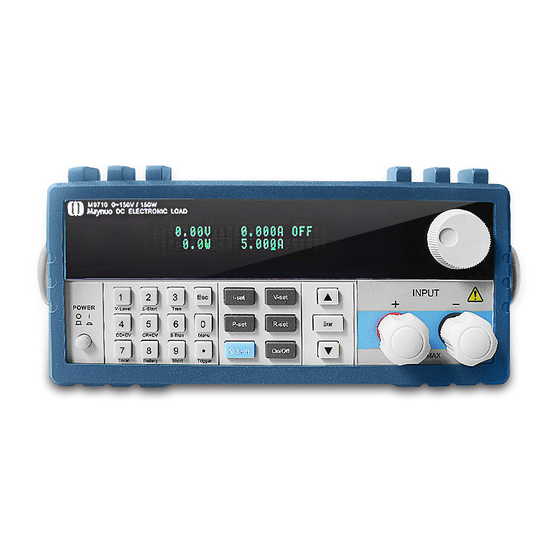
Diagram 3.2 Front panel ① The upper half is the black Vacuum Fluorescent Display (VFD) display screen. ② Robtary knob, Turn to adjust the setting values. ③ Numeric keys 0-9, ESC key, secondary key functions ④ Keypad: set up the current,voltage,power,resistance modes(I-set, V-set, P-set, R-set, Shift and On-Off);Scroll through menus and options ⑤... -
Page 12: Menu Operation
Setting up a constant current Switch to CV mode V-Set Setting up a constant voltage Switch to CW mode P-Set Setting up a constant power Switch to CR mode R-Set Setting up a constant resistance Multi-purpose Shift Used in conjunction with other keys to perform diverse functions and applications(for example: shift+0/Menu key will launch the menu function) Turn DC electronic Load on/off... - Page 13 SEPARATE Single BAUD RATE SET Setting the modem Baud rate 2400 baud 9600 baud 14400 baud 28800 baud 57600 baud 115200 baud COMM.PARITY Setting Communications Parity mode NONE No Parity EVEN Even Parity Odd Parity ADDRESS SET Setting an Address 1~200 The address is the input number (1-200).
- Page 14 completed STEP LENGTH Step length(1~200) STEP n 1~whole step length CURRENT Set current TIME Duration EXIT AUTO TEST LOAD AUTO TEST Select automatic test files 1~8 EDIT AUTO TEST Edit automatic test files STEP LENGTH Set the entire step length STEP n WORK MODE Load OFF mode...
-
Page 15: Chapter 4 Panel Operation
Chapter 4 Panel Operation 4.1 Basic Operation Mode There are four operation modes for the DC electronic load: 1. Constant Current (CC) 2. Constant Voltage (CV) 3. Constant Resistance (CR) 4. Constant Power (CW) 4.1.1 Constant Current Operation Mode (CC) In this mode, the DC electronic load will synchronize with a current in accordance with the programmed value regardless of the input voltage. -
Page 16: Loading And Unloading Constant Current Mode
If you want to fine tune the constant current value, rotate the encoder knob to adjust the value. Rotating clockwise will increase the value and rotating it counter-clockwise will decrease the value. Note: if the constant current value you want to set is beyond the maximum constant current value capability of the DC load, the current value will stop increasing even if you continue to rotate the encoder knob clockwise. -
Page 17: Soft Start Constant Current Mode
will show the word CC_UN or Unreg. CC_UN means the load was successfully set into the expected constant current value; Unreg means the load could not adjust itself to the desired constant current value. Please check thatthe power supply under test has been correctly connected and power switched on; make sure thatthe voltage set is normal and the selected constant current value is within the range of the UUT. -
Page 18: Constant Resistance Operation Mode (Cr)
Load input voltage Load input voltage Diagram 4.4 Constant CurrentShift Mode back into Constant Voltage Mode When in standard constant current mode, press the Shift+4(CC+CV) keys to enter into the constant current shiftto constant voltage mode. When the VFD display shows CC TO CV VOLT=xxxxxxxxV indicating the current constant voltage value, press the numeric keys and decimal point key to enter the constant voltage value desired followed by pressing the Enter key to confirm. -
Page 19: Setting Up A Standard Constant Resistance Mode
Diagram 4.5 Constant Resistance Mode 4.1.2.1 Setting up a Standard Constant Resistance Mode pressing the R-SET key the VFD display will show STANDARD RESI=xxxxxxxxΩ indicating the presentconstant resistance. In order to place the DC Electronic Load into the standard constant resistance mode, press the numeric keys and decimal point key to selct the desired values. -
Page 20: Shifting From Constant Resistance To Constant Voltage Mode
4.1.2.3 Shifting from Constant Resistance to Constant Voltage Mode Diagram 4.6 Shifting from Constant Resistance to Constant Voltage Mode By shifting from constant resistance into constant voltage mode, the power supply under test can avoid damage from a current strike.. From the standard constant current mode, press the Shift+5(CR+CV) keys to enter the constant current shifting to constant voltage mode. -
Page 21: Setting Up Standard Constant Voltage Mode
Diagram4.7 Constant Voltage Mode 4.1.3.1 Setting Up Standard Constant Voltage Mode Pressing the V-SET key - will display STANDARD VOLT=xxxxxxxxV indicating the current constant voltage value set-up field. Here, enter the constant voltage value desired, followed by pressing Enter. Now theDC load will be in standard constant voltage mode. If the input state is OFF , then the upper right right corner of the VFD display will show OFF. -
Page 22: Softstart Constant Voltage Mode
the maximum output current of the unit under test does not exceedthe range of maximum current that the DC load can absorb. From the loading and unloading constant voltage mode, press the Shift+1(V_Level) keys, and the load will go back to the standard constant voltage mode. 4.1.3.3 SoftStart Constant Voltage Mode Softstart constant voltage mode enables the DC Electronic Load to function as a condensive load, simulating electric capacity which is in direct proportion tothe rise time of the softstart. -
Page 23: Setting Up A Standard Constant Power Mode
in linear increments. Accordingly, the equation ofload power(=V * I)will remain constant in the power setting. Load input Load input voltage voltage Power set Power set Load current Load current Diagram 4.9 Constant Power Mode 4.1.4.1 Setting up a Standard Constant Power Mode Press the P-SET key, and the VFD panel displaysSTANDARD POWER=xxxxxxxxW indicating the selection screen for constant power. -
Page 24: Dynamic Testing Operation
the numeric selector keys and decimal point key to enter the unload voltage valuedesired, followed by pressing the Enter key to confirm. Now the load will be in the loading and unloading constant power mode. If the input state is OFF, then the upper right corner of the VFD display will show OFF. Press the On/Off key to change the input state to ON. -
Page 25: Trigger Mode(Trigger)
10ms 10ms 10ms 10ms TRIG TRIG TRIG TRIG Diagram 4.11 Pulse Operation Mode 4.2.3 Trigger Mode(TRIGGER) In this mode, when the dynamic test operation is turned on, the DC electronic load will switch the state between value A and value B afterreceiving a trigger signal. Diagram 4.12 Trigger Operation Mode 4.2.4 Setting up Dynamic test operational Parameters Press the Shift+6(S_Tran) keys, and the DC Electronic Load's VFD display shows LEVEL A... -
Page 26: Waveform Control
ready for each of the 3 dynamic test operation modes. Select the dynamic operation mode desired by pressing the up or down keys followed by pressing the Enter key to confirm. 4.2.5 Waveform Control 4.2.5.1 Square Wave When set in the Continuous mode, with the rise time and fall time are both set tozero, the output wave is a square wave. -
Page 27: List Operation
0.02mS to1310.7mS; if the minimum time is set at 2mS, then the duration of each step ranges from 2mS to 131070mS. 4.2.7.1. List Operation 1) Press the Shift+0 keys to enter the menu operation, and then use the ▲ and ▼ keys to get to MENU LIST, followed by keying Enter to confirm. -
Page 28: Automatic Test Operation
constant power mode, constant resistance mode, short circuit mode. Four comparison choices are available: current comparison,voltage comparison, power comparison and resistance comparison. Moreover, the delay time of each step can also bevaried. The delay time of each steprange from 0.1~25.5S, depending on the quickness and accuracy required. When each automatic test is over, the DC electronic load will indicate a pass or a fail result.. -
Page 29: Setting Up Automatic Test Trigger Output Mode
as a test suspended mode. Setting the delay time of any certain step at 25.5S, the load will stop and not proceed to the next step until a trigger signal is provided to continue the test. The trigger signal can be made either by the hardware on the back-panel, or by using the Shift+Trigger or the On/Off keys on the VFD display panel. -
Page 30: Input Control
meaning the DC electronic load is waiting for test initiation or remainingin the suspended mode respectively. Please retrigger it so ttesting continues onward. After each test is completed, the lower right corner of the VFD display will show either PASS or FAIL. If failure occurs, the buzzer will sound. -
Page 31: Protection Functions
DC Electronic Load Mode Changes Software Maximum Power Set Software Maximum Current Set Diagram 4-14 Software Maximum Setting Value 4.5 Protection Functions The DC E lectronic Load features the following protection functions. 4.5.1 Over Voltage Protection (OV) If input voltage exceeds the maximum voltage range of the load, it will automatically shut down the input. -
Page 32: Over Power Protection (Ow)
electronic load is 30A. When any value beyond 30A is input, the load will default back to 30A.Besides, the maximum current value input is closely related to current resolution. If the maximum current value set is below 3A, the load's current resolution will be 0.01mA; if the maximum current value set is above 3A, then the load's current resolution will be only 0.1mA. - Page 33 input terminals on the front panel of the DC electronic load. Selecting the BP will disable the remote measurement function on the rear panel. TERMINAL SELECT BACK means the input terminals on the rear panel of the load. Selecting these back panel terminals will disable the remote measurement function of the BPs on the load's front panel.
-
Page 34: Battery Testing
4.7 Battery Testing Experimentation has proven that the DC Electronic Load is the best way to confirm the operability of most batteries.. With the correct load test set-up, the battery expectant life curve can be confirmed.The electronic loads can currently be used to test about any type of the battery. For batteries that are embedded in other equipment or placed in uninterrupted power service systems, it is vital to use a DC electronic load for testing battery life status. -
Page 35: Communication Protocol
115200 baud. 1) Setting upadditional addresses and communication parameters The additional address is a single byte with 16 hexadecimal system data; the M97 series DC electronic loads will only respond to the request data frame that has the same additional address. -
Page 36: Setup Baudrate
4.8.3 Data The M97 series loads operate in the Modbus protocol. Accordingly, in some data frames, the date length is fixed, but in other data frames, the length is not fixed. According to this protocol, all the hexidecimal data and the floating point number are fixed in the High Byte and the unfixed data length fields are in the Low Byte. -
Page 37: Complete Command Frame Analysis
4.8.6 Complete Command Frame Analysis 1. Read Coil Status (0x01) Read Coil Status Example Query Field Name Byte length Example Value Slave Address 1~200 Function Code 0x01 Starting Address 0~0xFFFF O. of Points 1~16 CRC Error Check Read Coil Status Example for aLogical Response Filed Name Byte length Example Value... - Page 38 Coil Address 0~0xFFFF Force Data (Coil Status) 0x0000 or 0xFF00 CRC Error Check Force Single Coil Example in an Illogical Response Field Name Byte length Example Value Slave Address 1~200 Function Code 0x85 Abnormal Code 01~04 CRC Error Check A value of 0xFF00 will force the coil to turn ON, and 0x0000 forces the coil to be turn OFF. All other values are invalid and will not affect the coil status.
-
Page 39: Coil With The Register Address Allocation
From table 4.8.7.1 below, we know that the register address of the present voltage value is 0x0B00, Query: 0x01 0x03 0x0B 0x00 0x00 0x02 0xC6 0x2F The Corresponding Logical Response: 0x01 0x03 0x04 0x41 0x20 0x00 0x2A 0x6E 0x1A, within which, 0x41 0x20 0x00 0x2A is the read-back voltage valueand the corresponding floating point value is 10V. - Page 40 REMOTE 0x0503 1: remote input voltage ISTATE 0x0510 Input status: 1= input ON, 0= intput OFF TRACK 0x0511 Tracking status: 1=voltage tracking; 0=current tracking MEMORY 0x0512 1:input state memory VOICEEN 0x0513 1: audible key sound ON/OFF CONNECT 0x0514 1: multi 0= single ATEST 0x0515 1: Automatic test mode...
-
Page 41: Definition Of The Command Register Cmd
double type UCCCV 0x0A1D constant current shift constant voltage register:double type UCRCV 0x0A1F Constant resistance shift constant voltage register, double type 0x0A21 dynamic mode A phase current register, double-type 0x0A23 dynamic mode B phase current register, double-type TMAWD 0x0A25 dynamic mode pulse-width register,... -
Page 42: Common Operational Function Descriptions
CC Soft Start Dynamic Mode Short Circuit Mode List Mode CC Loading And Unloading Mode CV Loading And Unloading Mode Loading Unloading Mode CR Loading And Unloading Mode CC Mode Switch To CV Mode CR Mode Switch To CV Mode Battery Test Mode CV Soft Start Changin System Parameters... - Page 43 Table 7. Short-circuit operation: Operation Register Value Description Preset mandatory Multi-Registers Table 8. CC mode operation: Operation Register Value Description Preset IFIX Double Optional Multi-Registers Preset mandatory Multi-Registers Table 9. CV mode operation: Operation Register Value Description Preset UFIX Double Optional Multi-Registers Preset...
- Page 44 Table 13. CV mode soft-start: Operation Register Value Description Preset UFIX Double Optional Multi-Registers Preset TMCVS Double Optional Multi-Registers Preset mandatory Multi-Registers Table 14. CC loading and unloading mode: Operation Register Value Description Preset IFIX Double Optional Multi-Registers Preset UCCONSET Double Optional Multi-Registers...
- Page 45 Preset UCRONSET Double Optional Multi-Registers Preset UCROFFSET Double Optional Multi-Registers Preset mandatory Multi-Registers Table 18. CC mode switch to CV mode: Operation Register Value Description Preset IFIX Double Optional Multi-Registers Preset UCCCV Double Optional Multi-Registers Preset mandatory Multi-Registers Table 19. CR mode switch to CR mode: Operation Register Value...
-
Page 46: Remote Operation
Preset TMTRANRIS Double Optional Multi-Registers Preset TMTRANFAL Double Optional Multi-Registers Preset MODETRAN Optional Multi-Registers Preset mandatory Multi-Registers Table 22. System parameter setting mode: Operation Register Value Description Preset IMAX Double Optional Multi-Registers Preset UMAX Double Optional Multi-Registers Preset PMAX Double Optional Multi-Registers Force Single Coil... - Page 47 Photo 4. 9.2 M-133 (DB 9 pin to USB) Note:An industry standard RS-232 interface cable between the M97XX and a regular PC will not facilitate communication between the devices. The dongle on the M-133 provides the necessary switiching to enable proper communication. 1.
- Page 48 DB9 Serial Interface 1 +5V 2 TXD 3 RXD 4 NC 5 GND 6 NC 7 NC 8 NC 9 NC The output of DB9 interface on the rear-panel of the power supplier is TTL voltage level, so the pin outs of the voltage level shift cable(M-131 or M-133)must be set-up to match the PC before connecting the DB9 interface with the serial interface on PC.
- Page 49 Note:An industry standard RS-232 interface cable between the M97XX and a regular PC will not facilitate communication between the devices. The dongle on the M-133 provides the necessary switiching to enable proper communication. 株式会社ロイノス...
-
Page 50: Quick Reminders
User Manual. Wear gloves when you start the operation and always beware of electric shock hazard!. Don’t use the equipment without regard for personal safety. Certification and Warranty M97 Series Electrical Loads are warranted to meet its published technical specifications upon shipment from the factory. Warranty This product is warranted against defects in material and workmanship for a period of one year from date of shipment. - Page 51 Disclaimer Manufacturer reserves the right to make specification(s) changes to product(s) and its accompanying documentation, at any time, and without previous notification to it's customers. 株式会社ロイノス...
Need help?
Do you have a question about the M97 series and is the answer not in the manual?
Questions and answers