Advertisement
Quick Links
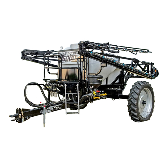
6000
1050 Gallon Tank w/60' or 72' Boom
General Information
Thank You and Congratulations on purchasing your
new sprayer. The purpose of this manual is to assist
you in operating and maintaining your sprayer.
Any Questions, Comments or Problems: Call your nearest AG SPRAY Location
and speak with one of our Friendly Technical Support Staff.
BAKERSFIELD, CA
COLUMBUS, NE
877-724-2236
800-274-1025
MANKATO, MN
NEWTON, KS
507-388-6295
800-394-7662
OWNER'S MANUAL
DOTHAN, AL
800-227-4098
PASCO, WA
800-634-2026
SHOP ONLINE @ WWW.AGSPRAY.COM
SERIES
SPRAYER
Please read it carefully, as it furnishes information
which will help you achieve years of trouble-free
operation. All units can be custom equipped to
meet all your spraying needs.
FARGO, ND
HOPKINSVILLE, KY
701-280-2862
800-637-7172
TEMPE, AZ
877-974-7166
[5195078
(09/18)]
VISIT US ONLINE @
WWW.AGSPRAY.COM
Page 1
Advertisement

Related Manuals for AG SPRAY 6000 Series


Summary of Contents for AG SPRAY 6000 Series
- Page 1 All units can be custom equipped to you in operating and maintaining your sprayer. meet all your spraying needs. Any Questions, Comments or Problems: Call your nearest AG SPRAY Location and speak with one of our Friendly Technical Support Staff. [5195078...
-
Page 2: Table Of Contents
Tank Rinse Operation Spray Controller Operation Sprayer Start-Up Procedure/Initial Start-Up Trouble Shooting Service & Maintenance Break-In/Foam Marker Greasing Spray Control Valve Wiring/Filter Cleaning Winterizing/Storage 21-36 Parts Breakdowns Hypro Warranty Info Limited Warranty Page 2 6000 SERIES SPRAYERS OPERATION & MAINTENANCE MANUAL... -
Page 3: Introduction
INTRODUCTION procedures. 1. Read and understand the Operators Manual and all safety signs before using. 11. Spray only when potential for chemical drift is at a 2. Place all controls in neutral, stop tractor engine, minimum. Even small amounts can affect turn monitor off, set park brake, remove ignition neighboring crops or sensitive plants and people. - Page 4 Left and right outer boom (Figure 6) Left and right break away (Figure 7) To adjust, loosen jam nut, turn position bolt to the required position and retighten jam nut. Page 4 6000 SERIES SPRAYERS OPERATION & MAINTENANCE MANUAL...
- Page 5 OPEN CENTER SYSTEM Figure 3 PARTS LIST Part # Qty. Part Description 212-025 BOLT 5/16-18 x .75 214-002 18 CABLE TIE BLACK 7" 259-018 LOOM CLAMP .75" od 302-749 MANI ASSY 0807 SDA 2SA CLSD INTG DTR 12V WP6400-4PT6801-8ORFD 319-639 HRN ASSY 15CON 18GA OTR 12P(12) DTR 3P(3)-14DTP 2P(2) 30' CLOSED CENTER SYSTEM Figure 4...
- Page 6 To ensure optimal boom performance never run boom in fully down position. Doing so eliminates boom ride accumulator. Note: Once tower cylinder bottoms out raise 1” for low- est recommended sprayer height. Page 6 6000 SERIES SPRAYERS OPERATION & MAINTENANCE MANUAL...
- Page 7 SPRAYER OPERATION CONTINUED This spring-loaded-to-neutral-center toggle switch con- trols the right outer boom function. Move the switch up Figure 8 and hold to pivot the right outer boom in and down to extend. Release the switch, the right outer boom will stop moving and it will remain at that position.
-
Page 8: Folding/Unfolding Procedure
5 sec- onds after the boom is fully extended. (Figure 9) 4. Hold down on “main lift” boom switch to lower boom to desired spray height. To ensure optimal Figure 10 Page 8 6000 SERIES SPRAYERS OPERATION & MAINTENANCE MANUAL... - Page 9 PLUMBING OPERATION Figure 11 Components: 1. Main Tank Valve 2. Drain Valve 3. Quick Fill Valve 4. Agitation/Rinse Valve 5. Gate Valve 6. Inductor Rinse Valve 7. Inductor Activation Valve 8. Inductor Tank Valve 9. Rinse Tank Valve 10. Front Agitation Valve 11.
- Page 10 Main Tank Fill Valve (2” Quick Fill) Sprayer Controls Agitation Rinse Tank Fill Valve (2” Quick Fill) Sprayer Controls Rinse Tank Main Tank Shut Off Safety Valve (Under Tank. Not Pictured) Sprayer Controls Main Tank Page 10 6000 SERIES SPRAYERS OPERATION & MAINTENANCE MANUAL...
-
Page 11: Spray Controller Operation
TANK RINSE OPERATION Fresh water rinse tank located behind the main tank is 9. Turn spray control valve from Rinse Tank to Agita- designed to allow the operator to rinse the sprayer tion (valve 1) without having to leave the field. 10. -
Page 12: Sprayer Start-Up Procedure
(Figure 13) NOTE: Start with control knob at center position. NOTE: If liquid pump does not prime on start up, run Wet/Dry control at full wet until prime. Page 12 6000 SERIES SPRAYERS OPERATION & MAINTENANCE MANUAL... -
Page 13: Trouble Shooting
2. Water conditions (soft or hard) will also vary either Tracer Pink (hot pink) or Tracer Blue foaming action Your local coop will probably be colorants from Ag Spray Equipment. able to advise which foam concentrate works best with local water conditions. - Page 14 14. TO SPRAY - Turn the Flow Control to Rate 1 or Rate 2 (preference). - The speed you need to travel is dependent on the rate at which you are spraying. Page 14 6000 SERIES SPRAYERS OPERATION & MAINTENANCE MANUAL...
- Page 15 2630 JD RATE CONTROLLER WITH PWM SETUP 1. After hooking up all wiring between tractor and sprayer, turn the system on. 2. Make sure all nozzles are open with desired tips installed. 3. From the Menu, select Rate Controller 4. Setup your Implement type - Select Pull Behind Sprayer, enter a name and tank size.
-
Page 16: Service & Maintenance
5. Before applying pressure to chemical system, make sure that all connection are tight and that all hoses and fittings are in good condition. 6. Relieve pressure from hydraulic circuit before servicing or disconnecting from tractor. Page 16 6000 SERIES SPRAYERS OPERATION & MAINTENANCE MANUAL... - Page 17 BREAK-IN Although there are no operational restrictions on the sprayer when used for the first time, it is recommended 1. Re-torque all wheel bolts, fasteners and that the following mechanical items be checked: hardware. A. After operating for 1/2 hour 2.
-
Page 18: Greasing
White TeeJet 844 & 854 Black Orange Yellow Green TeeJet 734 & 744 White Blue Brown Black Raven 330 & 440 White Wht/Brwn Black/Wht Blue Brown Black Raven 440 & 450 Page 18 6000 SERIES SPRAYERS OPERATION & MAINTENANCE MANUAL... - Page 19 SPRAY CONTROL VALVE WIRING 1. The motorized ball valves equipped on the sprayer 2. Each motorized ball red wire connects to the 12V require 12V constant power and ground to make terminal. Each motorized ball valve black wire will actuate. When 12V is sent from the controller thru connect to ground terminal, and each motorized the signal wire per each section the valve will open as...
- Page 20 Tire pressure. 8. Go through the pre-field checklist before using. e. All sprayer and hydraulic lines, fittings and connections. Tighten as required. 3. Lubricate all grease fittings. 4. Replace any defective parts. Page 20 6000 SERIES SPRAYERS OPERATION & MAINTENANCE MANUAL...
- Page 21 SHOP ONLINE @ WWW.AGSPRAY.COM Page 21...
- Page 22 Page 22 6000 SERIES SPRAYERS OPERATION & MAINTENANCE MANUAL...
- Page 23 5085016 - Hub Assembly Part # Qty. Part Description "758" Hub 5031149 Cone Bearing 5031152 Inner Cone Bearing 5031170 Inner Race 5046366 Hub Cap 5072498 Grease Seal (for 758 Hub) P151407 Stud Bolt, 5/8"-18 UNF P702217 Inner Race 5275474 - Break Away Clasp Part # Qty.
- Page 24 Page 24 6000 SERIES SPRAYERS OPERATION & MAINTENANCE MANUAL...
- Page 25 SHOP ONLINE @ WWW.AGSPRAY.COM Page 25...
- Page 26 Page 26 6000 SERIES SPRAYERS OPERATION & MAINTENANCE MANUAL...
- Page 27 SHOP ONLINE @ WWW.AGSPRAY.COM Page 27...
- Page 28 Page 28 6000 SERIES SPRAYERS OPERATION & MAINTENANCE MANUAL...
- Page 29 PARTS LIST Part # Qty. Part Description 5006337 1/2-13nc Hex Flanged Whiz Nut Gr. 5 5006345 3/8-16nc Hex Flanged Toplock Nut Gr. 5 5006367 5/16-18nc Hex Flanged Toplock Nut Gr. 8 5012015 10 Grease Zerk, 1/4"-28 Thread 5027050 Accumulator Clamp Plate 5034085 H.H.C.S., 3/4"-10 x 2"...
- Page 30 1"-8nc Hex Flanged Toplock Nut, Grade 8 5034742 Flng HH Bolt 3/4"-10 x 8" 5034750 Flng HH Bolt 1"-8 x 3" 5085016 Hub Assembly (758) (8-Bolt) 5279355 Small Axle Center Weldment 5279357 Small Axle RH Weldment Page 30 6000 SERIES SPRAYERS OPERATION & MAINTENANCE MANUAL...
- Page 31 RFM 60 P Flowmeter Replacement Parts 063-0171-793 Raven Part # Part Description 106-0159-514 Body, RFM 60 P Flowmeter 063-0171-673 Rotor/Magnet Assembly 063-0171-674 Hub/Bearing Assembly, Upstream 063-0171-769 Hub Assembly, Downstream 335-0000-278 Ring, Retaining, Internal 063-0173-062 Stud Bearing 435-3002-017 Clamp, Cable 310-0002-137 Screw, Thread Forming 063-0171-669 Sensor, Assembly, External PL450BEC-FB - Electric Shut-Off Flow Back Ball Valve Manifold Part #...
- Page 32 The Hypro hydraulic control assembly is designed to directly mount to modified Hypro HM series hydraulic motors. The control assembly provides a convenient solution for increased efficiency and damage prevention from abuse conditions. Page 32 6000 SERIES SPRAYERS OPERATION & MAINTENANCE MANUAL...
- Page 33 3376-1670 - Hypro Cleanload CAUTION: Only Use Genuine Hypro Replacement Parts NOTE: When ordering parts, give quantity, part number, description and complete model number. Tube Kit No. 3430-0833 Reference numbers are used ONLY to identify Contains: Tubing (Ref. 18) (Ref. 19) (Ref. 20), parts in the drawing and are NOT to be used as one screw (not shown), &...
- Page 34 Valve, Check-12 3320-0078 Valve, Check-10 3320-0080 Valve, Flow Control HM1 3320-0081 Valve, Flow Control HM4 2525-0036 Solenoid 2220-0129 Screw 2404-0443 Hydraulic Control Assy HM1 2404-0452 Hydraulic Control Assy HM4 2520-0212 Cable Page 34 6000 SERIES SPRAYERS OPERATION & MAINTENANCE MANUAL...
- Page 35 Service Instructions The three valves used in the hydraulic control assembly are screw-in cartridge type valves and are replaceable. Each valve must be installed with the correct tightening torque to ensure proper operation. If the valve is tightened above the specified torque value, the valve internals may be damaged causing the valve to stick.
- Page 36 SS Flat Washer, 3/8 2270-0142 2404-0443 Valve Flow Control Assembly 2406-0007 Pipe Plug 2500-0144R Motor, Hyd HM1C 2520-0212 Cable, Hydraulic Valve 6031-0548 Label, Blank L-1546 CI PM 9306 L-1575 CI PM Hydraulic Control Page 36 6000 SERIES SPRAYERS OPERATION & MAINTENANCE MANUAL...
-
Page 37: Limited Warranty
WHAT REMEDIES ARE AVAILABLE UNDER THIS LIMITED WARRANTY. If the conditions set forth above are fulfilled and the Equipment or any part thereof is found to be defective, Ag Spray Equipment shall, at its own cost, and at its option, either repair or replace the defective Equipment or part. - Page 38 8464 KYRENE RD, 85284 507.377.6295 316.283.4444 509.488.6631 480.705.8047 Toll Free: 800.722.9376 Toll Free: 800.394.7662 Toll Free: 800.634.2026 Toll Free: 877.705-8047 F: 507.388.4668 F: 316.293.4646 F: 509.488.2927 F: 480.705.8048 MANKATO@AGSPRAY.COM NEWTON@AGSPRAY.COM OTHELLO@AGSPRAY.COM TEMPE@AGSPRAY.COM Page 38 6000 SERIES SPRAYERS OPERATION & MAINTENANCE MANUAL...
Need help?
Do you have a question about the 6000 Series and is the answer not in the manual?
Questions and answers