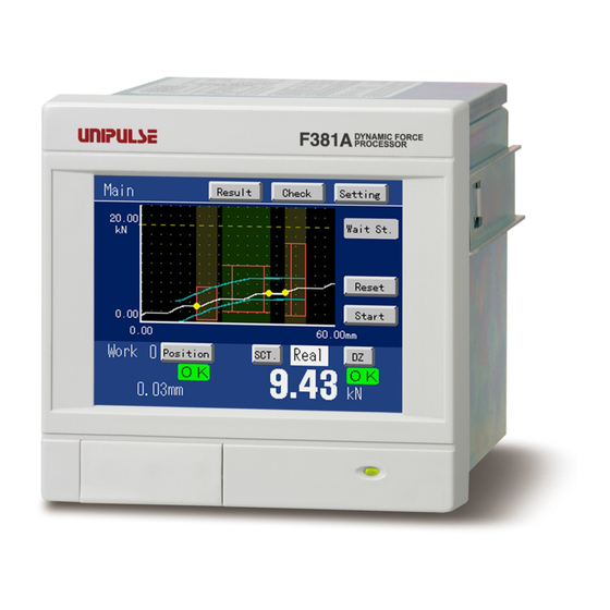
Unipulse F381A Operation Manual
Digital indicator
Hide thumbs
Also See for F381A:
- Operation manual (164 pages) ,
- Operation manual (29 pages) ,
- Operation manual (59 pages)
Table of Contents
Advertisement
Advertisement
Table of Contents

Related Manuals for Unipulse F381A


Summary of Contents for Unipulse F381A
- Page 1 F381A/F388A Ethernet I/F OPERATION MANUAL 01FEB2015REV.3.01...
- Page 2 Introduction Introduction The Ethernet I/F option is an interface to carry out communications with F381A/F388A(s) through an Ethernet. Supported functions are set value read/write, waveform read/write, hold result read, wave No. read/write, etc. WARNING The F381A/F388A(s) is factory-set as follows: ・IP address (192.168.0.1)
-
Page 3: Table Of Contents
3. F381A/F388A setting ........ -
Page 4: Part Names
LINK (Orange) How to establish communications ・Network check Check the network environment in which the F381A/F388A(s) is to be connected. ① The F381A/F388A and client are connected ②The F381A/F388As and client exist on the in a one-to-one relationship. - Page 5 2.How to establish communications Set the IP address, subnet mask, and default gateway. ① When the F381A/F388A and client are connected in a one-to-one relationship IP address: Set the same network address as that of the client, and set a unique address avoiding overlap with the client.
- Page 6 For use at 10Mbps, use STP (category, 3, 4, 5) cable(s). For use at 100Mbps, use STP (category 5) cable(s). * UTP cable(s) can also be used, but use of STP cable(s) is recommended. ① When the F381A/F388A and client are connected in a one-to-one relationship. Use a cross cable. F381A/F388A PC etc.
- Page 7 Check that the IP address is not used in other equipment. ii) Turn on the power of the F381A/F388A, and execute a PING command from the client to the IP address of the turned-ON F381A/F388A, and check that a response is made.
-
Page 8: F381A/F388A Setting
Upon establishment of connection, the IP address of the connection-established equipment is displayed under "Connect IP" on the Ethernet setting item screen of the F381A/F388A. (If the F381A/F388A is connected with the client through a router, the address of the router close to the F381A/F388A is displayed.) If connection is not established, the settings of the client software may be wrong. - Page 9 Displays the MAC address of the an Ethernet I/F option. Connect IP: Displays the IP address of the equipment the TCP connection of which is currently established with the F381A/F388A. If TCP connection is not established, "---.---.---.---" is displayed. Keys Accepts the currently-input value.
- Page 10 3.F381A/F388A setting Explanation for setting Equipment ID: Set the equipment ID. When connecting two or more F381A/F388As to Ethernet, set each equipment ID to identify them. * This is the same as the equipment ID of the SD card slot option.
- Page 11 3.F381A/F388A setting - About the combination of the IP address and subnet mask Unsettable combination: When the IP address and subnet mask are expressed in binary, IP addresses in which all the bits 0-specified to the subnet mask become 0 or 1 cannot be set.
-
Page 12: Ethernet I/F Option Self-Check
3.F381A/F388A setting Example) Combinations in which the default gateway cannot be set Decimal number Binary number Subnet mask 255.255.000.000 11111111.11111111.00000000.00000000 IP address 192.169.036.150 11000000.10101001.00100100.10010110 Default gateway 192.168.036.001 11000000.10101000.00100100.00000001 Decimal number Binary number Subnet mask 255.255.000.000 11111111.11111111.00000000.00000000 Default gateway 192.169.000.000 11000000.10101001.00000000.00000000 192.169.255.255... -
Page 13: Communication Connector
Decimal number Binary number Subnet mask 255.255.255.000 11111111.11111111.11111111.00000000 IP address 192.168.000.001 11000000.10101000.00000000.00000001 Network address 192.168.000 11000000.10101000.00000000 Network address 192.168.0 Client F381A/F388A F381A/F388A IP address: 192.168.0.5 IP address: IP address: 192.168.0.1 192.168.0.2 Subnet mask: 255.255.255.0 Subnet mask: Subnet mask: 255.255.255.0 255.255.255.0... - Page 14 ・What is a server? The host waiting for a connection in establishing a connection is called a server. The F381A/F388A is a server, and after power-on, it is brought to a state in which it waits for connection from the client side.
-
Page 15: Cautions In Creating Client Software
- Port number Set 50381 to the port number. - Keep alive The F381A/F388A sends a packet at intervals of 30 seconds, and checks three times. -Checking of communications carried out with an intended F381A/F388A For use of two or more F381A/F388As, set the equipment ID avoiding overlap to identify them. -
Page 16: Communication Commands
8.Communication commands Communication commands By transmitting commands from the host, operations corresponding to the commands are executed. (①F381A ②F388A) -List of items that can be communicated Set value, operation, Item group Read Write Cal. Reference display item Main Load (display) ×... - Page 17 8.Communication commands Set value, operation, Item group Read Write Cal. Reference display item First Setting X-axis Setting Time/DPM Change Set value read/ × 〇 〇 set value write command Phase Select Set value read/ × 〇 〇 set value write command Wave Reference Set value read/ ×...
- Page 18 8.Communication commands Set value, operation, Item group Read Write Cal. Reference display item First Setting System Backlight Set value read/ × 〇 〇 Setting set value write command (ON Time) Backlight Set value read/ × 〇 〇 set value write command (bright→dark)...
- Page 19 8.Communication commands Set value, operation, Item group Read Write Cal. Reference display item Settings by Hold Setting Change of Sct. Set value read/ × 〇 〇 work (common to all work) set value write command [Work 0 to 15] Use Sct. Set value read/ ×...
-
Page 20: Set Value Read Command (First Setting)
Y-axis Setting in the example F381A/F388A’s return (In normal processing) Delimiter (STX) Data of the specified set value Command received by the F381A/F388A Header (If there is no header, no data will result.) F381A/F388A’s return (In abnormal condition) (STX) Delimiter NG No. -
Page 21: Set Value Write Command (First Setting)
Display Range Setting in the example F381A/F388A’s return (In normal processing) (STX) Delimiter Data of the specified set value Command received by the F381A/F388A Header (If there is no header, no data will result.) F381A/F388A’s return (In abnormal condition) Delimiter (STX)... -
Page 22: Set Value Write Command (Work Setting)
Item group (See the list of set value commands.) Work Setting in the example F381A/F388A’s return (In normal processing) (STX) Delimiter Command received by the F381A/F388A Header (If there is no header, no data will result.) F381A/F388A’s return (In abnormal condition) Delimiter (STX)... -
Page 23: Zero Calibration Command
Item group (See the list of Zero Calibration commands.) Y-axis Setting in the example F381A/F388A’s return (In normal processing) Delimiter (STX) Command received by the F381A/F388A Header (If there is no header, no data will result.) F381A/F388A’s return (In abnormal condition) (STX) Delimiter NG No. -
Page 24: Hold Result Read Command
If "1" is read to Waveform update, go to step ② , and if "1" is not read, repeat step ① . (For transmitting the SAMPLE command continuously, do it at intervals of 100ms or more.) Host (Transmission to the F381A/F388A) S A M Delimiter F381A/F388A’s return... - Page 25 If the first section = the last section, only the specified section can be read. Space (20H) F381A/F388A’s return (In normal processing) (STX) , Command received by the F381A/F388A Data of the specified first section , , , , Load...
-
Page 26: Result Read Command
If "1" is read to Waveform update, go to step ② , and if "1" is not read, repeat step ① . (For transmitting the SAMPLE command continuously, do it at intervals of 100ms or more.) Host (Transmission to the F381A/F388A) S A M Delimiter F381A/F388A’s return... -
Page 27: Waveform Update Check/Equipment Id Read Command
8.Communication commands ② Read the measurement results. Host (Transmission to the F381A/F388A) R E S Delimiter Displacement Displacement Displacement Displacement F381A/F388A’s return (In normal processing) Load Load Load Load , 2 (STX) , , , Command received Total result Section1... -
Page 28: Waveform Read Command
If "1" is read to Waveform update, go to step ②, and if "1" is not read, repeat step ① . (For transmitting the SAMPLE command continuously, do it at intervals of 100ms or more.) Host (Transmission to the F381A/F388A) S A M Delimiter F381A/F388A’s return... - Page 29 (Back): fixed at 0000 fixed at 2047 displacement (Back): Hyphen(2dH) 0000 to 2047 Space (20H) Command received by the F381A/F388A Header (If there is no header, no data will result.) F381A/F388A’s return (In abnormal condition) Delimiter (STX) NG No.
-
Page 30: Waveform Write Command
8.Communication commands F381A/F388A’s return (In normal processing) (STX) SP 0 Command received by the F381A/F388A Waveform data ・ ・ ・ ・ ・ Waveform data at the start of the range at the end of the range Waveform data Amount of data: Data for the specified range “the end of the range –... - Page 31 8.Communication commands F381A/F388A’s return (In normal processing) Delimiter (STX) Command received by the F381A/F388A Header (If there is no header, no data will result.) F381A/F388A’s return (In abnormal condition) Delimiter (STX) NG No. 1: Receipt of a statement different from the command format...
-
Page 32: Wave No. Read Command
Alphanumeric characters and symbols from 1 to 20 digits Setting range (20H to 7EH, 80H to FCH) F381A/F388A’s return (In normal processing) Delimiter (STX) Command received by the F381A/F388A Header (If there is no header, no data will result.) F381A/F388A’s return (In abnormal condition) Delimiter (STX)... -
Page 33: Display Read Command
4: H/L -9999 to +9999 2: HI 5: NG (with a decimal point) 3: LO Command received by the F381A/F388A Header (If there is no header, no data will result.) , , Load error status Displacement: -9999 to +32000 (with a decimal point) Time: - - - - - ,... -
Page 34: Time Read Command
F381A/F388A’s return (In normal processing) 9 SP 2 Delimiter (STX) : : Command received by the F381A/F388A Header (If there is no header, no data will result.) F381A/F388A’s return (In abnormal condition) Delimiter (STX) NG No. 1: Receipt of a statement different from the command format... -
Page 35: List Of Commands To Read Set Values
8.Communication commands - List of commands to read set values (①F381A ②F388A) Item group Setting item Command (transmission to the F381A/F388A) First Setting Y-axis Delimiter ①Exc. Voltage Setting (CR) ②Input Select Unit Delimiter (CR) Decimal Place Delimiter (CR) Zero Calibration... - Page 36 8.Communication commands Return (by the F381A/F388A) Input range (display range) Delimiter ①0: 2.5 1: 10 [V] ± (CR) ②0: ±10V 1: ±20mA Delimiter ± See "- Unit setting list" on page 49. (CR) Delimiter 0: 0 1: 0.0 ± 2: 0.00 3: 0.000 (CR) ①-3.333 to 3.333 [mV/V]...
- Page 37 8.Communication commands Item group Setting item Command (transmission to the F381A/F388A) First Setting X-axis Analog Filter Delimiter Setting (Only ①) (CR) Digital Filter Delimiter (CR) Commu- Speed Delimiter nication (CR) Setting Data Bit Delimiter (CR) Parity Bit Delimiter (CR) Stop Bit...
- Page 38 8.Communication commands Return (by the F381A/F388A) Input range (display range) Delimiter 0: 10 1: 30 2: 100 ± (CR) 3: 300 [Hz] Delimiter Times ± 0, 2 to 999 [ (CR) Delimiter 0: 1200 1: 2400 2: 4800 ± 3: 9600 4: 19.2k 5: 38.4k [bps]...
- Page 39 8.Communication commands Item group Setting item Command (transmission to the F381A/F388A) Settings by Display Y Start Point Delimiter work Range (CR) Setting [Work 0 to 15] Y End Point Delimiter (CR) X Start Point Delimiter (CR) X End Point Delimiter...
- Page 40 8.Communication commands Return (by the F381A/F388A) Input range (display range) Delimiter ± -10000 to 10000 (CR) Y-axis Start Point + 0: 25 1: 50 2: 100 3: 200 4: 300 5: 400 Delimiter ± 6: 500 7: 1000 8: 2000...
- Page 41 8.Communication commands Command (transmission to the F381A/ Item group Setting item F388A) Settings by Load HI/LO Limit Delimiter work (HI limit) (CR) [Work 0 to 15] Load HI/LO Limit Delimiter (LO limit) (CR) DPM HI/LO Limit (HI limit) Delimiter (CR)
- Page 42 8.Communication commands Return (by the F381A/F388A) Input range (display range) Delimiter ± -9999 to +9999 (CR) Delimiter ± -9999 to +9999 (CR) Waveform Reference; Front 0 to 2047 (× Measurement Length/2000) Delimiter Waveform Reference; Back ± -2047 to 0 (× Measurement Length/2000)
-
Page 43: List Of Commands To Write Set Values
8.Communication commands - List of commands to write set values (①F381A ②F388A) Item group Setting item Command First Setting Y-axis Setting ①Exc. Voltage ± ②Input Select Unit ± Decimal Place ± Equiv. Cal. ± (rated output) Equiv. Cal. ± (rated capacity) Overload ±... - Page 44 8.Communication commands (transmission to the F381A/F388A) Input range (display range) Delimiter ①0: 2.5 1: 10 [V] (CR) ②0: ±10V 1: ±20mA Delimiter See "- Unit setting list" on page 49. (CR) Delimiter 0: 0 1: 0.0 (CR) 2: 0.00 3: 0.000 Delimiter ①-9.999 to 9.999 [mV/V]...
- Page 45 8.Communication commands Item group Setting item Command First Setting Communication Speed ± Setting Data Bit ± Parity Bit ± Stop Bit ± Delimiter ± Header ± Flow Control ± Com. Mode ± System Setting Backlight ± (ON Time) Language ± Work Protect ±...
- Page 46 8.Communication commands (transmission to the F381A/F388A) Input range (display range) Delimiter 0: 1200 1: 2400 2: 4800 (CR) 3: 9600 4: 19.2k 5: 38.4k [bps] Delimiter 0: 7 1: 8 [bit] (CR) Delimiter 0: None 1: Even (CR) 2: Odd Delimiter 0: 1 1: 2 [bit]...
- Page 47 8.Communication commands Item group Setting item Command Settings by work Display Range Y Start Point ± [Work 0 to 15] Setting Y End Point ± X Start Point ± X End Point ± Hold Setting Change of Sct. (common to all work) ±...
- Page 48 8.Communication commands (transmission to the F381A/F388A) Input range (display range) Delimiter -10000 to 10000 (CR,CR+LF) Y-axis Start Point + 0: 25 1: 50 2: 100 3: 200 Delimiter 4: 300 5: 400 6: 500 7: 1000 (CR,CR+LF) 8: 2000 9: 3000 10: 4000...
- Page 49 8.Communication commands Item group Setting item Command Settings by work DPM HI/LO Limit (HI limit) [Work 0 to 15] Note1) ± DPM HI/LO Limit (LO limit) Note1) ± Section 1 to 5 Start Load ± Load Difference ± Rate ± Ordinal ±...
- Page 50 8.Communication commands (transmission to the F381A/F388A) Input range (display range) Waveform Reference; Front 0 to 2047 (× Measurement Length/2000) Waveform Reference; Back Delimiter -2047 to 0 (× Measurement Length/2000) (CR,CR+LF) * When End Displacement in Use Hold is selected; -9999 to 32000 * Setting HI limit <...
-
Page 51: List Of Zero Calibration Commands
Point of Section 1, Start Point of Section 2, …… Start Point of Section 5 and End Point of Section 5. - List of zero calibration commands Item group Setting item Command (transmission to the F381A/F388A) Y-axis Zero Delimiter Setting... -
Page 52: Unit Setting List
8.Communication commands - Unit setting list * Numbers are values of input range. Also, “0” results in no unit. - ①F381A Weight Force Pressure Length Angle Other μg μN μPa μm g/cm ° kg/m l/min μA g/ml μNm mg/m kg/m... - Page 53 8.Communication commands -② F388A Weight Force Pressure Length Angle Other μg μN μPa μm g/cm ° kg/m l/min μA g/ml μNm mg/m kg/m dyne kgm/s μV kdyne μbar mbar ftlb mPas inlb mmHg Ω inoz kΩ mm/s MΩ psia kgcm psig mm/min atom...
-
Page 54: Cautions
Once Section No. is written (with the currently-specified Work No.), it will be reflected afterward throughout reading and writing of hold settings. This section No. is just for Ethernet communications. The F381A/F388A’s section is not changed. Also, the Section display in Hold Setting is not changed. - About communications during measurement During measurement, writing or calibration cannot be carried out through communications, where only reading can be carried out. -
Page 55: Specifications
10.Specifications The saved IP address, subnet mask, and/or default gateway is not a The setting is changed when settable value. powering on. Check the settings, and then set again. Please reset after confirming If this message appears each time the power is turned on, there is a the setting.
Need help?
Do you have a question about the F381A and is the answer not in the manual?
Questions and answers