
Related Manuals for Killbros 590

Summary of Contents for Killbros 590
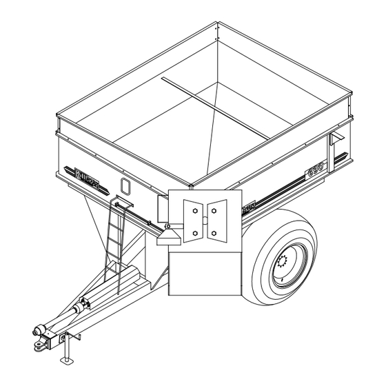
- Page 1 PART NO. 106260 OPERATOR’ S MANUAL PARTS CATALOG OM02504 Corner Auger Grain Carts 590 (After Serial No. D1949-) 690 (After Serial No. D1948-) 24325 ST. RT. 697W PH: 419-695-2060 DELPHOS, OH. 45833 FAX: 419-695-6875...
-
Page 2: Introduction
It is said that, "the best kind of a safety device is a careful operator." We, at Killbros. ask that you be that kind of operator. - Page 3 Guards and shields in place Hydraulic hoses properly routed/fittings tight OM02608 NOTE: Due to continuing improvements in the design and manufacture of KILLBROS products, and normal changes in the marketplace, all specifications contained herein are subject to change without notice.
-
Page 4: Table Of Contents
Table of Contents INTRODUCTION ..........2 ASSEMBLY INSTALLATION OF 690 SIDEBOARDS..18 SAFETY DECALS ........... 5 INSTALLATION OF OPTIONAL SAFETY ............6 HYDRAULIC DRIVE ........19 INSTALLATION OF SCALE UNIT ....20 OPERATIONS ELECTRICAL HOOK-UP ........7 PARTS TRACTOR HOOK-UP ........7 AUGER COMPONENTS ......... -
Page 5: Safety Decals
590/690 SAFETY DECALS OM02569 (Refer to pg. 31 for part numbers) -
Page 6: Safety
SAFETY AVOID POSSIBLE INJURY Keep hands, feet, clothing, and objects away from moving parts. Always use safety precautions. Most acci- dents are a result of failure to practice safety. Do not grease equipment when in operation. Accidents cause lost time and suffering. Do not operate the Grain Cart without reading DO NOT allow ANYONE to enter the box at this manual thoroughly. -
Page 7: Operations
Your Grain Cart is supplied with a seven-point SAE connector plug, which will adapt to the receptacle found on several new tractors on the market today. If not available, an SAE J S60A seven-point outlet socket can be purchased from your Killbros dealer (order #104838). SAE SEVEN POINT... -
Page 8: Operation In Field
If any one of these is not adjusted properly please read the SERVICE section outlined in the manual or contact your nearest KILLBROS dealer for further information. With everything in good operating condition, be sure to close flow control gates before use. -
Page 9: Coupling The Pto
A. Only use a completely shielded drive sys- tem: PTO drive systems with complete shielding, include the tractor master shield and imple- ment shielding installed all the time. If any component of the shield system has been removed for any reason it, or an identical replacement part, must be installed before operation. -
Page 10: Dismantling
1. Chains must be fitted to allow sufficient articulation of the shaft in all working po- sitions. Care must be taken to be sure that chain does not become entangled with drawbar hitch or other restrictions during operation or transport of machine. 2. -
Page 11: Important Scale Information
PLEASE READ THE FOLLOWING INFORMATION BEFORE USING YOUR SCALE! THE FOLLOWING STEPS MUST BE CONSIDERED WHEN USING YOUR SCALE AND TO REAL- IZE ITS BEST PERFORMANCE. DIGI-STAR SCALES ARE MANUFACTURED TO PROVIDE 1/2% MAXIMUM ERROR. A GOOD INSTALLATION AND PROPER USE ARE REQUIRED IN ORDER TO OBTAIN ADVERTISED ACCURACY. -
Page 12: Operating The Scale
The ZERO / BALANCE will “ balance off” the OPERATING THE SCALE: dead load such as a trailer, bin, or platform weight. Turning ON the scale: “ZERO” is displayed to show completion of 1. Press [ON] the step and the scale is then placed in the GROSS mode. - Page 13 POWER CABLE CONNECTIONS: WIRE COLOR WIRE FUNCTIONS Battery (+12 VDC) 2. If in Gross mode, press [NET/GROSS]. The [NET/GROSS] is an alternating action BLACK GROUND key. If the scale is in the GROSS mode, ORANGE Remote Alarm Out+ pressing the [NET/GROSS] key will place BLUE Remote Input it in the NET mode.
-
Page 14: Scale Troubleshooting
TROUBLE SHOOTING GUIDE FOR THREE POINT (3 LOAD CELL) SCALE SYSTEMS WHILE USING THE TROUBLESHOOTING GUIDE, SEVERAL SECTIONS REFER TO STANDING OR HANGING YOUR WEIGHT OVER EACH LOAD CELL. THIS IS AN IMPORTANT PART OF TROUBLESHOOTING YOUR SYSTEM, (WE CALL IT WALKING THE CORNERS). THIS IS DONE TO CHECK THE SCALES ABILITY TO WEIGH YOU CORRECTLY WITH ALL FOUR LOAD CELLS. - Page 15 EQUIPMENT REQUIRED: #2 PHILLIPS SCREWDRIVER SMALL FLAT BLADE SCREWDRIVER PENCIL AND PAPER NOTE: THIS PROCEDURE WAS WRITTEN BY DIGI-STAR (J-STAR) SCALE SYSTEMS UTILIZ- ING EZ INDICATORS (EZ 150, EZ 210, OR EZ 320). IF YOU HAVE AN OLDER SCALE SYSTEM WHICH UTILIZES AN OMP SERIES INDICATOR, YOU SHOULD OBTAIN A DIFFERENT TROUBLE- SHOOTING PROCEDURE.
-
Page 16: Service
OM02524 SERVICE TIPS SELECTING PROPER TRACTOR FOR YOUR CART Approximate loaded weight of cart -690 -> 41,500 Lbs. -590 -> 35,000 Lbs. Approximate loaded hitch weight of cart -690 -> 3,900 Lbs. -590 -> 3,700 Lbs. WHEEL NUTS Check all wheel nuts for tightness before first load. -
Page 17: Auger System
FLOW CONTROL GATE AUGER SYSTEM The Flow Control Gate is designed to prevent grain form putting an excess load on the Annually check all bolts, nuts, and set screws. horizontal auger during initial start-up. If gate Perform lubrication as specified. The vertical is not working properly check: auger screw on upper and lower auger tubes are designed to self align while extending upper... -
Page 18: Adjustable Gearbox Operation
ets out of the hardware bag tied to the frame tom side of the cart for the flow control gate. of the cart. Bolt the corner brackets on the (3) U-brackets are welded along the inside outside of the sideboards using the top set of channel for protection of the hydraulic hoses. -
Page 19: Installation Of Optional Hydraulic Drive
INSTALLATION OF OPTIONAL HYDRAULIC DRIVE Assembly (Anti-Reverse Kit) The optional hydraulic drive unit eliminates 1. Follow steps 1-4 in Standard Kit assem- use of P.T.O. hook-up. Also available for this bly. kit is an optional anti-reversing kit and/or a 2. Connect 15” hydraulic hose to ends of double Q/D set (refer to pg. -
Page 20: Installation Of Scale Unit
INSTALLATION OF SCALE UNIT NOTE: For protection against the environment. HITCH ASSEMBLY It is recommended that the indicator be mounted in tractor cab when applicable. 1. Remove the 3/4” x 5” bolt (102520), lockwasher (100186), and nut (102521) to remove the swivel hitch (102524.) 1. -
Page 21: Auger Components
Auger Components OM02507 ITEM PART NO. DESCRIPTION ITEM PART NO. DESCRIPTION 103482 U.V.A. Screw 102427 Cylinder Pin w/ Clips 911444-162 1/4” x 1-1/2” Expansion Pin 100782 2-1/2” x 20” Hyd. Cylinder 9389-115 1/2” x 5” HH Bolt 101791 2-1/2” Hyd. Cylinder Repair Kit 100719 Comp. -
Page 22: Flow Control Components
Flow Control Components OM02508 ITEM PART NO. DESCRIPTION ITEM PART NO. DESCRIPTION 100744 1-1/2” Hanger Bearing 103440 Bulkhead Union 102204 1-1/2” Bearing Insert 105336 Indicator Rod 91299-065 3/8” x 3-1/2” Gr.8 Bolt 103432 2” x 20” Hydraulic Cylinder 100815-B Vertical Screw Coupler 102191 2”... -
Page 23: Power Train Components
Power Train Components SEE DIAGRAM PG. 23 SEE PG. 24 OM02509 ITEM PART NO. DESCRIPTION ITEM PART NO. DESCRIPTION 9394-010 1/2” Hex Nut 103544 Snap Ring 9404-025 1/2” Lockwasher 9389-101 1/2” x 1” Bolt 94119 1/8” Grease Fitting, 90 Deg. 103412 Gear Box 9405-088... -
Page 24: Gear Box Diagram
Gear Box Diagram OM02515 ITEM PART NO. DESCRIPTION ITEM PART NO. DESCRIPTION 103549 Shaft, Input (with gear) 103545 3/8” -18 Pipe Plug Hex Socket 103555 Oil Seal 103548 Output Shaft 103663 Shim, 65.3mm x 45.3mm 103664 103553 Ball Bearing Assembly 103558 Snap-Ring 103660... -
Page 25: Power Take-Off Shaft
Power Take-off Shaft OM02510 ITEM PART NO. DESCRIPTION ITEM PART NO. DESCRIPTION 103585 Bolt and Nut, Clutch Spring 103573 Female Tube 103584 Clutch Pressure Plate 103571 Yoke, Female Tube 103581 Slip Clutch Lining 103544 Snap-Ring 103582 Clutch Inner Plate 103570 8mm Grease Fitting 103580 Slip Clutch Bushing... -
Page 26: Axle/Hub Components
Axle/Hub Components PART NO. ITEM PART NO. DESCRIPTION ITEM DESCRIPTION 101033 3” Seal (CR30087) 100851 4-3/8” Seal (CR43771) 92734 100747 2-1/2” Bearing (39585) 3.54” Bearing (HM218248) 92733 2-1/2” Cup (8-414799) 100858 3.54” Cup (HM218210) 92457 92457 Hub Stud (3/4” -16 x 2 1/2” ) Hub Stud (3/4”... -
Page 27: Scale Components
Scale Components OM02517 ITEM PART NO. DESCRIPTION ITEM PART NO. DESCRIPTION 103699 Complete Pkg. w/Clevis Hitch 104210 Complete Pkg. w/ Clevis Hitch 105363 Complete Pkg. w/Spade Hitch 105371 Complete Pkg. w/ Spade Hitch 9000948 Junction Box w/ Cable 9000948 Junction Box w/ Cable 91257 5/16”... -
Page 28: Sideboards
Sideboards ITEM PART NO. DESCRIPTION ITEM PART NO. DESCRIPTION 103884W Sideboard, 14” x 10’ Rear Taper 106255W Sideboard, 25” x 10’ Rear Taper 103882W Right Sideboard, 6” x 12’ 106256W Right Sideboard, 20” x 12’ 103988W 6” Corner Angle 106259W 20”... -
Page 29: Light Package
Light Package OM02506 ITEM PART NO. DESCRIPTION 103629 COMPLETE PACKAGE 103603 Work Light 103618 3/8” Mini Cord Clip 103600 Amber/Red Light (L.H.) 103617 Steel Body Clip 103599 Work Light Harness 104258 Main Harness 9000106 6” Plastic Tie 103601 Amber/Red Light (R.H.) 9523 1/4”... -
Page 30: Miscellaneous
Miscellaneous OM02523 ITEM PART NO. DESCRIPTION ITEM PART NO. DESCRIPTION 102693 Window Weather-strip 103435 Hydraulic Hose, 180” 102608 Glass Window 103536 Hydraulic Hose, 156” 9394-002 1/4” Nut 91299-155 3/4” x 5” Gr.8 Bolt 9389-007 1/4” x 1-1/2” Bolt 102523 Hitch Coupler 9404-017 1/4”... -
Page 31: Decals
Decals OM02505 ITEM PART NO. DESCRIPTION 104420 Killbros 96812 Warning 96814 Danger 105355 Open 95045 Danger 95046 Disengage 100793 Close 96753 Farm Safety 100795 Tighten Lug Nuts 93552 Warning 104288 104289 104286 12” Arrow 104284 24” Stripe 91302 Caution - To Avoid Injury... -
Page 32: Auxilary Hydraulic Drive Unit
Auxiliary Hydraulic Drive Unit OM02470 ITEM PART NO. DESCRIPTION ITEM PART NO. DESCRIPTION 105431 Complete Kit 95988 Hydraulic Motor 91383 3/4” Q/D Coupler 9390-443 5/8” x 10” HH Bolt 103347 Male Coupler 9405-100 5/8” Flat Washer 105170 Hydraulic Hose (15” ) 101958 5/16”... - Page 33 NOTES:...
- Page 34 KILLBROS 24325 State Route 697W DELPHOS, OHIO 45833 RT/SS/G:\Operator Manuals\Grain Carts\106260.p65/111099...
Need help?
Do you have a question about the 590 and is the answer not in the manual?
Questions and answers