Table of Contents
Advertisement
Project Documentation | UMRR-0A Radar Sensor Documentation
Project Number:
...
SMS Project Number:
Project Title:
General Purpose Radar Sensor
Keyword(s):
UMRR-0A radar sensor, type 31 antenna
Date:
August 22, 2013
Document:
UMRR-0Axxxx Type31 Operational Description.docx
Version:
1
CONFIDENTIAL AND PROPRIETARY
The Information contained in this document shall remain the sole exclusive property of s.m.s smart microwave sensors GmbH and shall not
be disclosed by the recipient to third parties without prior consent of s.m.s smart microwave sensors GmbH in writing.
UMRR-0Axxxx Type31 Operational Description.docx Version 1 I Page 1 of 19 I August 22, 2013
Advertisement
Table of Contents

Related Manuals for smartmicro UMRR-0A

Summary of Contents for smartmicro UMRR-0A
- Page 1 Project Documentation | UMRR-0A Radar Sensor Documentation Project Number: SMS Project Number: Project Title: General Purpose Radar Sensor Keyword(s): UMRR-0A radar sensor, type 31 antenna Date: August 22, 2013 Document: UMRR-0Axxxx Type31 Operational Description.docx Version: CONFIDENTIAL AND PROPRIETARY The Information contained in this document shall remain the sole exclusive property of s.m.s smart microwave sensors GmbH and shall not be disclosed by the recipient to third parties without prior consent of s.m.s smart microwave sensors GmbH in writing.
-
Page 2: Table Of Contents
1 Contents Contents ........................2 Abbreviations ......................3 Introduction ....................... 4 General description ....................5 Sensor description ....................5 Transmit Signal ....................6 General Performance Data ..................6 Hardware ........................7 UMRR sensor ....................... 7 Sensor Dimensions ....................9 Cables and connectors ....................11 Sensor connector .................... -
Page 3: Abbreviations
2 Abbreviations Analog-to-digital converter Controller area network Digital-to-analog converter Digital signal processing; digital signal processor EEPROM Electrically erasable programmable read-only memory FMCW Frequency modulated continuous wave MMIC Monolithic microwave integrated circuit Random access memory RS485 Physical communication layer standard EIA RS-485 Serial peripheral interface UMRR Universal medium-range radar... -
Page 4: Introduction
3 Introduction This document is a short documentation of the general purpose universal medium range radar (UMRR) UMRR-0Axxxx radar sensor with type 31 antenna in the housing version 0306xx. CONFIDENTIAL AND PROPRIETARY The Information contained in this document shall remain the sole exclusive property of s.m.s smart microwave sensors GmbH and shall not be disclosed by the recipient to third parties without prior consent of s.m.s smart microwave sensors GmbH in writing. -
Page 5: General Description
4 General description 4.1 Sensor description The main task of the UMRR is the detection of any reflectors in the field of view, to measure the distance, the relative speed and the angle to the shortest reflector (and to other reflectors), to detect motion and to track (filter) the results over time. -
Page 6: Transmit Signal
4.2 Transmit Signal The UMRR transmit frequency is located in the 24 GHz ISM band (24050 MHz to 24250 MHz), the used bandwidth is smaller than 200 MHz. The maximum transmit power is 12.7dBm. Antenna type 31 is used, consisting of one transmit and two receive antennas, both linear polarized. -
Page 7: Hardware
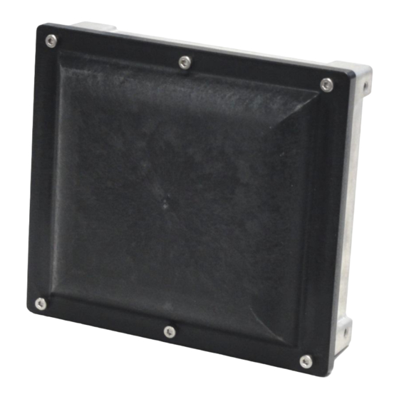
5 Hardware 5.1 UMRR sensor An example picture of a UMRR (universal medium-range radar) sensor (housing type 0306xx) is shown in the figures below. Figure 1: UMRR sensor, housing type 0306xx, front. CONFIDENTIAL AND PROPRIETARY The Information contained in this document shall remain the sole exclusive property of s.m.s smart microwave sensors GmbH and shall not be disclosed by the recipient to third parties without prior consent of s.m.s smart microwave sensors GmbH in writing. - Page 8 Figure 2: UMRR sensor housing 0306xx rear CONFIDENTIAL AND PROPRIETARY The Information contained in this document shall remain the sole exclusive property of s.m.s smart microwave sensors GmbH and shall not be disclosed by the recipient to third parties without prior consent of s.m.s smart microwave sensors GmbH in writing. UMRR-0Axxxx Type31 Operational Description.docx Version 1 I Page 8 of 19 I August 22, 2013...
-
Page 9: Sensor Dimensions
5.2 Sensor Dimensions All values given in mm. Figure 3: Sensor Front side. Figure 4: Sensor Top, Left and Right Side. CONFIDENTIAL AND PROPRIETARY The Information contained in this document shall remain the sole exclusive property of s.m.s smart microwave sensors GmbH and shall not be disclosed by the recipient to third parties without prior consent of s.m.s smart microwave sensors GmbH in writing. - Page 10 Figure 5: Sensor Rear Side. CONFIDENTIAL AND PROPRIETARY The Information contained in this document shall remain the sole exclusive property of s.m.s smart microwave sensors GmbH and shall not be disclosed by the recipient to third parties without prior consent of s.m.s smart microwave sensors GmbH in writing. UMRR-0Axxxx Type31 Operational Description.docx Version 1 I Page 10 of 19 I August 22, 2013...
-
Page 11: Cables And Connectors
(CAN bus termination between CAN_L and CAN_H). The resistor is nevertheless required at either end of a CAN bus and is in most cases integrated in the cable delivered along with the sensor (if cable is manufactured by Smartmicro). CONFIDENTIAL AND PROPRIETARY The Information contained in this document shall remain the sole exclusive property of s.m.s smart microwave sensors GmbH and shall not... -
Page 12: Data Interfaces
7 Data interfaces 7.1 CAN data interface This specification gives a detailed description of the CAN data communication used in the UMRR based systems on the sensor CAN. The UMRR is compliant with CAN 2.0B standard. CAN is a very robust full duplex bidirectional interface. 7.2 CAN-Settings Baud Rate: 500kBit/s or lower... -
Page 13: Rs485 Data Interface
Figure 7: CAN bit timing for UMRR sensor (eCAN module on DSP TMS320F28335) Figure 8: CAN bit timing as defined by the CAN protocol 7.3 RS485 data interface The RS485 interface from the UMRR sensor has a predefined speed of 230400 baud/s. Typical other data rates are between 921.6kBit/s and 56.7kBit/s. - Page 14 Table 2: RS485 message structure Byte\Bit 0xCA 0xCB Start sequence (4 x UINT8) 0xCC 0xCD Data payload (n x UINT8) XOR Checksum (UINT8) 0xEA 0xEB End sequence (4 x UINT8) 0xEC 0xED Every data message consists of its own message ID, the number of used data bytes and the data bytes itself.
- Page 15 Table 3: Structure of a RS485 data payload block Byte\Bit High CAN message ID (UINT16) CAN message length (UINT8) CAN data payload (length x UINT8) The sensor receives only one message per cycle. It is important to wait for the end sequence to send an additional command.
-
Page 16: Transceiver Schematics
7.4 Transceiver schematics In Figure 9 an extract of the DSP board schematic of the UMRR is given. As can be seen in this figure, the CAN pins of the DSP TMS320F28335 are connected to a CAN transceiver which is connected to the pins CAN_L and CAN_H. Similarly, the RS485 pins of the DSP are connected to a RS485 transceiver, which is connected to the pins RS_485_L and RS_485_H. -
Page 17: Designated Use
8 Designated use The UMRR general purpose medium range radar is suitable for any application where the distance to and relative radial speed of large objects has to be measured. Typical applications are: Automotive: measure shortest distance to obstacle. Robotics: measure shortest distance to obstacle. Security: detect motions and measure distance to moving object. -
Page 18: Frequency Approval
9 Frequency Approval 9.1 Declaration of Conformity for USA This device complies with Part 15 of the FCC Rules. Operation is subject to the following two conditions: (1) This device may not cause harmful interference, and (2) this device must accept any interference received, including interference that may cause undesired operation. -
Page 19: Declaration Of Conformity For Canada
9.2 Declaration of Conformity for CANADA 9.2.1 Declaration of Conformity in English This device complies with RSS-310 of Industry Canada. Operation is subject to the condition that this device does not cause harmful interference. 9.2.2 Déclaration de conformité en francais Cet appareil est conforme au CNR-310 d'Industrie Canada.
Need help?
Do you have a question about the UMRR-0A and is the answer not in the manual?
Questions and answers