Advertisement
B5B-7206-00
6 S ERVICE MANUAL
2015
RA027<Rev.001>
COPYRIGHT © 2015 JVC KENWOOD Corporation
1
PRECAUTION. . . . . . . . . . . . . . . . . . . . . . . . . . . . . . . . . . . . . . . . . . . . . . . . . . . . . . . . . . . . . . . . . . . . . . . . . 1-2
2
SPECIFIC SERVICE INSTRUCTIONS . . . . . . . . . . . . . . . . . . . . . . . . . . . . . . . . . . . . . . . . . . . . . . . . . . . . . . 1-3
3
DISASSEMBLY . . . . . . . . . . . . . . . . . . . . . . . . . . . . . . . . . . . . . . . . . . . . . . . . . . . . . . . . . . . . . . . . . . . . . . 1-13
4
ADJUSTMENT . . . . . . . . . . . . . . . . . . . . . . . . . . . . . . . . . . . . . . . . . . . . . . . . . . . . . . . . . . . . . . . . . . . . . . . 1-13
5
TROUBLESHOOTING . . . . . . . . . . . . . . . . . . . . . . . . . . . . . . . . . . . . . . . . . . . . . . . . . . . . . . . . . . . . . . . . . 1-14
This product complies with the RoHS directive for the European market.
B5B-7206-00
SERVICE MANUAL
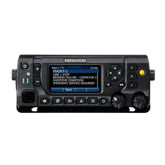
REMOTE CONTROL HEAD
COPYRIGHT © 2015 JVC KENWOOD Corporation
KCH-20R
TABLE OF CONTENTS
This product uses Lead Free solder.
No.RA027<Rev.001>
2015/6
Advertisement

Related Manuals for Kenwood KCH-20R


Summary of Contents for Kenwood KCH-20R
-
Page 1: Table Of Contents
B5B-7206-00 KCH-20R COPYRIGHT © 2015 JVC KENWOOD Corporation TABLE OF CONTENTS PRECAUTION............... . . 1-2 SPECIFIC SERVICE INSTRUCTIONS . -
Page 2: Precaution
Neither is any liability assumed for damages resulting from the use of the information contained herein. JVC KENWOOD Corporation reserves the right to make changes to any products herein at any time for improvement purposes. Bluetooth Copyrights The Bluetooth word mark and logos are registered trademarks owned by Bluetooth SIG, Inc. -
Page 3: Specific Service Instructions
Deck 2.1.1 Installing the Remote control head (KCH-20R) (1) Insert the cable into the interface unit (XC3-0090-20) con- The KCH-20R control head is used to remotely operate the nector (CN2) of the KRK-15B. NX-5700/5800 series transceiver. (2) Insert the flat cable into the interface unit connector (CN1) The KCH-20R is connected to the KCT-71 remote control cable. - Page 4 2.1.6 Connect the KRK-15B and KCH-20R with the KCT-71 (4) Insert the other lead wire with connector of the KCT-71 into (1) Insert one lead wire with connector of the KCT-71 into the the connector (CN5) of the KCH-20R.(Fig. 7) connector (CN3) of the KRK-15B.
- Page 5 2.1.7 Fixing method of KCH-20R microphone cord This mounting hardware is intended to protect the modular jack under use environment. (Microphone can be used without this mounting hardware.) Microphone cord should be fixed so that the curl portion is lower side.
- Page 6 2.2.1 Overview KCH-20R is a remote control panel with 2.75" LCD and extended keys. KCH-20R has built-in Bluetooth and micro SD card slot. The Bluetooth supports HSP. KCH-20R has two circuit units. XC3-010 is Sub unit and XC3-011 is Interface unit. There consist of a power supply circuit, audio circuit, control circuit and the Bluetooth circuit.
- Page 7 XC3-011 External Interface 53DC Class-D Audio Amplifier 5.4V DC/DC CN13 XC3-010 CAN transceiver 53DC Key backlight/LED indicator Level shift circuits , Audio circuits 5V AVR Modular Interface 39DC MPU core 3.9V DC/DC 1.2V DC/DC MPU,Mobile DDR, Codec DSP, 1.8V DC/DC Bluetooth circuits Level shift IC10...
- Page 8 RX Audio KCH-20R has two RX Audio input channels, AFIA+/- and AFIB+/-. And the MPU selects the one of the two channels, and then applied to digital potentiometer IC (IC22/XC3-010). (The channel to use is notified by serial communication from RF Deck.) The digital potentiometer IC adjusts RX Audio signal amplitude equal to the value of selected volume step, and output it.
- Page 9 Key detection KCH-20R has 19 keys. The keys except the AUX key and Power key is included in key-matrix circuit. Key-matrix consists of 4 input ports and 5 output ports. When key is pressed, the MPU starts scanning the keys and detects which key was pressed.
- Page 10 COMPONENTS DESCRIPTION 2.3.1 Sub unit (XC3-0100-20) Ref. No. Part Name Description Ref. No. Part Name Description Q15,Q16 DC switch DC-DC DC-DC CONVERTER (12DC) TRANSISTOR Mic AGC CONVERTER DC switch MOS IC CAN transceiver IC D1, 2 VARISTOR ESD protection MOS IC DC-DC Converter (39DC) DIODE Reverse current prevention...
- Page 11 TERMINAL FUNCTION Pin No. Name Function 2.4.1 Sub unit (XC3-0100-20) VSSD - Ground Pin No. Name Function VSSD - Ground IOVCC O 1.8V output I Switched power supply IOVCC O 1.8V output I Switched power supply O LCD driver RD signal I Switched power supply O LCD driver WR signal I Switched power supply...
- Page 12 Pin No. Name Function Pin No. Name Function O Clock output MICA+ I MIC signal input plus_A - Ground AFoA+ O AF signal output plus_A DAT0 I/O Data 0 ACC_MIC O AUX MIC signal output DAT1 I/O Data 1 AFi- I AF signal input minus I/O Card detect switch ACC_ME...
-
Page 13: Disassembly
Once the top cover is removed, it cannot be used again. <2> <2> <2> (2) Use tweezers to slightly lift the edge of the top cover. <1> < < 1> <1> SECTION 4 ADJUSTMENT This service manual does not describe ADJUSTMENT. (There is no adjustment item on KCH-20R.) (No.RA027<Rev.001>)1-13... -
Page 14: Troubleshooting
SECTION 5 TROUBLESHOOTING Fault Diagnosis of the BGA (Ball Grid Array) IC Overview A flowchart for determining whether or not the transceiver can be powered on (the LCD does not function even if the power switch is turned on) due to broken BGA parts. BGA parts MPU (IC14), mobile DDR (IC24), Flash memory (IC30) Checking SB (Battery) voltage... - Page 15 When a normal value is confirmed. Checking the output signal from the MPU If the /FRST is always 0V ,the MPU is broken. Checking the control signal output from the MPU. When an abnormal Remove D40 to check the voltage of Flash value is confirmed.
- Page 16 Failure diagnosis of the Bluetooth section Overview: When the Bluetooth function does not operate, use this flowchart to determine the problem. Major parts for a Bluetooth circuit IC14 IC13 IC12 UART UART ANT1 Bluetooth antenna (ANT1) Level LC filter (L30) conversion Bluetooth Antenna...
- Page 17 When a normal condition is confirmed. [The 19.2MHz clock is faulty] Verify the 19.2MHz clock circuit When an abnormal When an abnormal Verify the 19.2MHz clock Replace the X1, R60, R47, for the BT. (19.2M_BT) condition is confirmed. condition is confirmed. C52 : Square wave, C108 : Sine waveform, R48, C36, C39...
- Page 18 Press "Write" button in the window. When the transceiver starts to receive data, the [LOADING] display on LCD. The Firmware is written to DECK (NX-5700/NX-5800) and KCH-20R at the same time. g) If writing ends successfully, the checksum is calculated and a result is displayed.
- Page 19 SCHEMATIC DIAGRAM SUB UNIT (XC3-0100-20) SUB UNIT:XC3-0100-20 53DC R281 Customize4 CustomizeA CustomizeB CustomizeC KEYi3 C280 C283 C287 GREEN-LED_INDICATOR TP For Production $CN10,$CN11,$CN16,$CN17,$CN118,$CN19 RED-LED_INDICATOR S70-0901-05 S70-0901-05 S70-0901-05 S70-0901-05 D4,8,12,18 LED_KEY BACKLIGHT 3COLOR-LED_INDICATOR B30-2365-05 B30-2365-05 B30-2365-05 B30-2365-05 R282 Down Right Left Customize3 KEYi2 LED ON:2.47V /FRST...
- Page 20 MEMO (No.RA027<Rev.001>) 2-2...
- Page 21 INTERFACE UNIT (XC3-0110-20) Separate I/F /PRST /PRST /PSW /PSW MiCA+ MICA+ MiCA- MICA- MiCB+ MICB+ MiCB- MICB- 1SR154-400 REVERCE CURRENT PREVENTION HEAD UNIT I/F FZA10BS-5R0 NC(IGN) CN13 AFiA+ AFiA+ AFiA- AFiA- AFiB+ AFiB+ AFiB- AFiB- CAN+ CAN+ CAN- CAN- AFi+ AFi+ ACC_ME ACC_ME...
- Page 22 PRINTED CIRCUIT BOARD SUB UNIT (XC3-0100-20) --- Component side view (J7C-0041-00) --- ANT1 C279 C156 CN57 C100 C103 C106 C107 C109 C110 C284 C288 C282 IC19 IC27 R240 R165 C238 R162 C169 R287 IC22 J7C-0041-00 C170 R184 R288 C243 R164 C190 C155 R180...
- Page 23 SUB UNIT (XC3-0100-20) --- Foil side view (J7C-0041-00) --- IC12 IC34 R213 R132 R216 C212 C226 R107 C127 IC10 C116 IC34 C118 C123 C134 R168 R149 C138 R105 IC14 R123 R110 R121 R119 R118 R169 C294 R103 C220 C121 C122 C224 CN42 C113...
- Page 24 INTERFACE UNIT (XC3-0110-20) --- Component side view (J7C-0042-00) --- CN13 --- Foil side view (J7C-0042-00) --- J7C-0042-00 XC3-006/011 (No.RA027<Rev.001>) 2-6 2-6 (No.RA027<Rev.001>)
- Page 25 INTERCONNECTION DIAGRAM KCH-20R IC302 IC911 AF AMP POWER MODULE LA4425A 20pin Option CN57 CN731 VSSA VSSA VSSA R402 VSSD VSSD VSSD CN900 IOVCC IOVCC CN907 CN906 A U X I O 6 AUXIO6 A U X I O 7 AUXIO7...
- Page 26 BLOCK DIAGRAM Sub Unit (XC3-010) Interface Unit (XC3-011) IC24 IC14 W02-3785-05 TPS54240DGQ MM3404A50URE KEYo0 USB12 RVDD 5.0V 1.2V 3.9V DDR_A[0]~DDR_A[13] 39DC KEYo1 VOLTAGE 53DC CVDD DC/DC DC/DC DDR_DQM[0]~DDR_DQM[1] DDR_CLKP REGULATOR PLL0_VDDA CONVERTER CONVERTER DDR_BA[0]~DDR_BA[1] DDR_RAS mDDR DDR_CKE DDR_CS DDR_WE DDR_CAS PLL1_VDDA KEYo2 DDR_D[0]~DDR_D[15]...
- Page 27 PARTS LIST [KCH-20R] * SAFETY PRECAUTION Parts identified by the ! symbol are critical for safety. Replace only with specified part numbers. * BEWARE OF BOGUS PARTS Parts that do not meet specifications may cause trouble in regard to safety and performance.
- Page 28 Exploded view of general assembly and parts list Block No.M1MM INTERFACE UNIT<02> SUB UNIT<01> 3-2(No.RA027<Rev.001>)
- Page 29 A2D-0010-00 REAR PANEL B0K-0025-00 SD CARD CAP B1B-0040-00 ILLUMINATION GUIDE B3H-0005-10 LCD ASSEMBLY B4B-0008-00 CAUTION STICKER FCC PANEL B4D-0029-00 BADGE KENWOOD LOGO E3F-0050-00 FLAT CABLE 36PIN F0G-0002-00 MOLDING COVER F10-3225-05 SHIELDING COVER BLS 14.4x16.9(x3) F1A-0016-10 SHIELDING COVER SPCC F1B-0027-00 SHIELDING COVER BLS 41.1x25.1...
- Page 30 Electrical parts list SUB UNIT Symbol No. Part No. Part Name Description Local XC3-0100-20 RB521CM-30 DIODE *Note : This part cannot be replaced. There- B30-2365-05 WHITE/R/8 B30-2365-05 WHITE/R/8 fore, this part is not supplied as a service part. B30-2365-05 WHITE/R/8 B30-2365-05 WHITE/R/8...
- Page 31 Symbol No. Part No. Part Name Description Local Symbol No. Part No. Part Name Description Local CC73HCH1H101J C CAPACITOR 100PF J C138 CC73HCH1H220J C CAPACITOR 22PF J CK73HB1E104K C CAPACITOR 0.10UF K C140 CK73HB1C105K C CAPACITOR 1.0UF K CC73HCH1H101J C CAPACITOR 100PF J C141...
- Page 32 Symbol No. Part No. Part Name Description Local Symbol No. Part No. Part Name Description Local C221 CK73HB1E104K C CAPACITOR 0.10UF K RK73HB1J101J MG RESISTOR 100 J 1/16W C222 CK73HB1E104K C CAPACITOR 0.10UF K RK73HB1J104J MG RESISTOR 100K J 1/16W C224 CK73HB1E104K C CAPACITOR...
- Page 33 Symbol No. Part No. Part Name Description Local Symbol No. Part No. Part Name Description Local R114 RK73HB1J103J MG RESISTOR 10K J 1/16W R203 RK73HB1J222J MG RESISTOR 2.2K J 1/16W R115 RK73HB1J103J MG RESISTOR 10K J 1/16W R204 RK73HH1J473D MG RESISTOR 47K D 1/16W...
- Page 34 Symbol No. Part No. Part Name Description Local Symbol No. Part No. Part Name Description Local LB73G0AM-004 CHIP FERRITE BEADS S70-0901-05 TACT SWITCH LR79Z0EZ120M CHIP INDUCTOR S70-0901-05 TACT SWITCH LB73G0AM-004 CHIP FERRITE BEADS S70-0901-05 TACT SWITCH LB73G0AM-004 CHIP FERRITE BEADS S70-0901-05 TACT SWITCH LB73G0AM-004...
- Page 35 Symbol No. Part No. Part Name Description Local CC73HCH1H101J C CAPACITOR 100PF J CC73HCH1H101J C CAPACITOR 100PF J CK73GB1H105K C CAPACITOR 1.0UF K CK73HBB1H102K C CAPACITOR 1000PF K CK73GBB1H103K C CAPACITOR 0.01UF K CK73GBB1H103K C CAPACITOR 0.01UF K RK73FB2B332J MG RESISTOR 3.3K J 1/8W RK73HH1J683D...
- Page 36 Packing materials and accessories parts list Block No.M2MM Packing and accessories Block No. [M][2][M][M] Symbol No. Part No. Part Name Description Local B1B-0047-00 FILTER ------------ PACKING FIXTURE ------------ PAMPHLET ------------ PROTECTION BAG 60/110/0.07 ------------ PROTECTION BAG 200X350 ------------ PROTECTION BAG 100/250/0.07 ------------ PROTECTION BAG...
- Page 37 MEMO...
- Page 38 JVC KENWOOD Corporation Communications Systems Business Operation (No.RA027<Rev.001>) Printed in Japan...
Need help?
Do you have a question about the KCH-20R and is the answer not in the manual?
Questions and answers