Table of Contents
Advertisement
Quick Links
Download this manual
See also:
Manual
Assembly and operating instructions
DULCOMETER
®
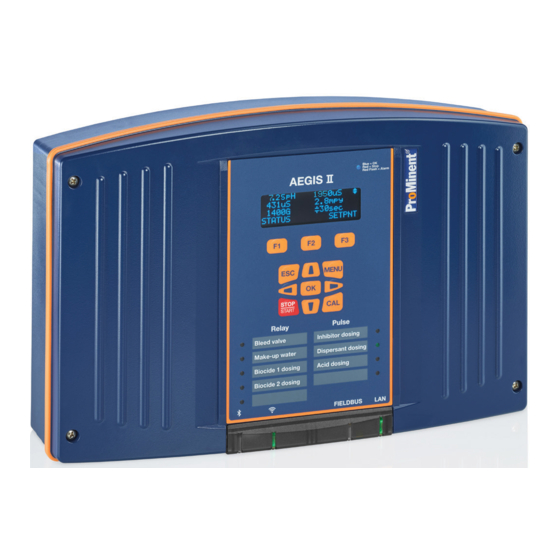
Aegis-II
Cooling Tower and Boiler Controller
Use your Tablet or Smartphone. I'm WiFi ready!
Please carefully read these operating instructions before use! - Do not discard this manual! The operator shall be responsible for any damage
caused by installation or operating errors! Technical changes reserved.
ProMinent Fluid Controls
136 Industry Drive Pittsburgh, PA, USA 15275-1014
Aegis II Installation 3/17
983367
BA_DM_225_03/18_EN
Advertisement
Table of Contents

Related Manuals for ProMinent Aegis-II


Summary of Contents for ProMinent Aegis-II
- Page 1 Please carefully read these operating instructions before use! - Do not discard this manual! The operator shall be responsible for any damage caused by installation or operating errors! Technical changes reserved. ProMinent Fluid Controls 136 Industry Drive Pittsburgh, PA, USA 15275-1014...
-
Page 2: Table Of Contents
Table of Contents OPERATING CONCEPT ........................... 5 1.1 T ............................5 RONT ANEL 1.2 F ........................... 6 UNCTIONS OF THE KEYS 1.3 C ......................6 HANGING THE PERATING ANGUAGE 1.4 K ..............................6 EYPAD NAVIGATING THE [MENU] DISPLAY ......................7 2.1 I ] .................... - Page 3 Table of Contents 9.5.3 Calibrating and checking probes ......................51 9.5.4 Cleaning and servicing probes ........................ 51 9.5.5 Calibration Notes ............................52 9.6 G ........................53 ENERAL ENSOR ALIBRATION 9.7 C ....................... 54 ALIBRATING AN MPEROMETRIC ENSOR 9.8 A ..........................55 NALOG ENSOR LARMS...
- Page 4 Table of Contents 11 SYSTEM MENU ............................... 88 11.1 ............................88 OMMUNICATIONS 11.1.1 How to Change the IP Address: ....................... 88 11.1.2 Web Interface Wi-Fi..........................89 11.2 ............................89 YSTEM ETUP 11.2.1 Site Name/Controller Name ........................89 11.2.2 Keypad Passwords........................... 89 11.2.3 Metric Units ..............................
-
Page 5: Operating Concept
Menu Navigation General non-discriminatory approach The following are highlighted separately in the document: In order to make it easier to read, this document uses the male form in grammatical structures but Safety Information with an implied neutral sense. It is aimed equally at Safety information is provided with detailed both men and women. -
Page 6: Functions Of The Keys
Menu Navigation The communication indication panel is located at the bottom center of the controller face. A green light indicates the function is available. If the port is in use, the green light blinks. Bluetooth Wi-Fi Fieldbus Ethernet (WLAN) (LAN) (LAN) Figure 3 Communication Status LEDs (Bluetooth and Fieldbus are not currently available. -
Page 7: Navigating The [Menu] Display
Menu Navigation Navigating the [Menu] display Name of menu item Jump to chapter [Home] Return to the default display (See below) [Adjust Set-points] Chapter 10.6.2 Feed Based on a Sensor [Prime, Force ON] Chapter 10.14 Prime, Force On a Relay [Water Meter Setup] Chapter 9.10.1 Configure a Digital Input as a Water Meter [Adjust Alarms]... -
Page 8: Input/Output Status [Momentary Display]
Menu Navigation 2.1 Input/Output Status [momentary display] 1- From main display press Down arrow key to select desired sensor 2- Use Right arrow key to momentarily see sensor information 3- Use Left arrow key to momentarily see any output that is tied to the selected input 4- Use ESC key to Exit Note: The momentary information will remain on the... -
Page 14: Safety And Responsibility
Safety and Responsibility Safety and Responsibility 4.1 Explanation of the safety information Introduction These operating instructions provide information on the technical data and functions of the product, as well as detailed safety information and are provided as guidance for the installer and operator. The safety information and notes are categorized according to the following scheme. -
Page 15: General Safety Notes
Safety and Responsibility 4.2 General Safety Notes Measure: Before opening the enclosure or before carrying out installation work, ensure the devices are voltage- free. Disconnect damaged, defective or modified devices from the power supply. WARNING! WARNING! WARNING! Danger from hazardous Live parts! substances! Operating faults! -
Page 16: Intended Use
As of this date, the physical controller is warranted for 2 years from the date of purchase as explained in the complete Prominent warranty. The complete warranty is found in the Prominent catalog Introduction and is available online at www.prominent.us. Changes to this warranty may not be shown in this manual. -
Page 17: Training
A trained user is a person who fulfills the requirements of an instructed person and who Trained user has also received additional training specific to the system from ProMinent or another authorized distribution partner. Trained qualified A qualified employee is deemed to be a person who is able to assess the tasks... -
Page 18: Functional Description
Dual Serial Input driver. actuators. The controller is also equipped to A full line of ProMinent sensors as well as communicate with some sensors using a proprietary signals from most 4-20mA devices are serial bus. -
Page 19: Mounting And Installation
Mounting and Installation Mounting and Installation User qualification, mechanical installation: trained qualified personnel, see Chapter 4.4 Users' qualifications. User qualification, electrical installation: Electrical technician, see Chapter 4.4 Users' qualifications. CAUTION! Mounting position and conditions Controller must be installed in a manner that the power plug The controller is rated for IP 65 liquid protection, can be pulled out easily or the and is equivalent to NEMA 4X (indoor) for air... -
Page 20: Scope Of Supply
Scope of Supply 6.1 Scope of supply The following components are included as standard: Description Quantity Controller AGIb Assembly material, complete Operating Manuals on Flash Drive General safety notes 6.2 Mechanical installation Figure 5 Attaching the wall Bracket 6.2.1 Wall mounting 1. -
Page 21: Electrical Installation
Mounting and Installation 6.3 Electrical Installation User qualification, electrical installation Electrical technician, see Chapter 4.4 Users' qualifications Moisture at the contact points It is important that you use suitable measures to protect plugs, cables and terminals from moisture and potential corrosion. Moisture at the contact points can interfere with the operation of the controller. WARNING! Safe operating status Both hardware and software safety precautions must be... -
Page 22: Specification Of The Cable Grips And Conduit Entries
Mounting and Installation 6.3.1 Specification of the cable grips and conduit entries Figure 8 All Dimensions in millimeters (mm) Page 22 of 102... -
Page 23: Sensor Seals And Termination Procedure
Mounting and Installation Figure 9 Use a screwdriver to break open a sealed enclosure entrance Figure 10 Examples of cable gland assembly. 1. Plug, 2 Cap, 3. Gland, 4. Connector Body, 5. Nut 6.3.2 Sensor Seals and Termination Procedure Select the correct fitting seals for the controller's cable openings. Seal the open holes with blanking plugs in the cord glands as shown. -
Page 24: Parking The Hood
Mounting and Installation 6.3.3 Parking the Hood The hood or cover of the Aegis II enclosure can be ‘parked’ so that access to the internal wiring and all of the display indications are accessible simultaneously as shown below. To park the hood, loosen the four captive screws until the hood can be carefully pulled straight out from the enclosure base. - Page 25 Mounting and Installation Building Power In Line Power out x3 AC powered Control Relay R1 AC powered Control Relay R2 Unpowered AC/DC Relay R3 Unpowered AC/DC Relay R4 Unpowered AC/DC Relay R5 Unpowered DC Contact P9 Unpowered DC Contact P8 Unpowered DC Contact P7 Unpowered DC Contact P6 Digital Input V (NAMUR) –...
- Page 26 Mounting and Installation Figure 14 Aegis II overall location of major components Page 26 of 102...
- Page 27 Mounting and Installation Figure 15 Aegis II motherboard general arrangement Page 27 of 102...
- Page 28 Mounting and Installation Figure 16 Main PC board Input Wiring diagram Page 28 of 102...
- Page 29 Mounting and Installation Figure 17A Main PC board Output Wiring diagram; Part 1: Relays R3 through P9 Page 29 of 102...
- Page 30 Mounting and Installation Figure 17B Main PC board Output Wiring diagram; Part 2: Relays R1, R2 and the Power block The ground and neutral connections are all tied together through the printed circuit board as shown in the schematic 17B. The hot (Line) wire does not link with the other L terminals until after it passes through the main fuse F3.
-
Page 31: Power In And Relay Output Termination
Mounting and Installation 6.3.5 Power In and Relay Output Termination All electrical wiring shall be performed by a licensed electrician, in accordance with local and national electric codes. The following wiring diagrams and information show typical configurations, but not all possible combinations of this versatile controller. - Page 32 Mounting and Installation To enter wires into the terminal blocks, (see figure 22) insert a small screwdriver or similar, into the spring box opening as shown, then push up on the driver handle. This will force the spring loaded metal slider downwards and open the wire grip below. These blocks accept a maximum of 14 gauge wire.
- Page 33 Mounting and Installation Relays R3, R4 and R5 have Dry Contact terminals. Unlike R1 and R2, they have no power. This allows the user to supply power from a remote source or use power from the Output side of the power block. In Figure 25, we show a jumper wire from the Fused Power output block Line terminal to the Com input on R3 –...
-
Page 34: Frequency Output Termination
6.3.6.1 Using a Universal Control Cable on a Pulse Output Relay Prominent pumps using the Universal Control cable will terminate using the brown, black and white wires as shown in Figure 30. This connection is not polarity sensitive. The black is common. - Page 35 The G input is for 4-20mA devices. This includes analog tank level, flow rate, temperature, analyzer signals, PLC signals, etc. The G input is not programmed for Prominent amperometric sensors including pH and ORP sensors that have been converted to 4-20mA. This input is not used for Pyxis or Little Dipper sensors as well. All of these sensors require the 4-20mA expansion input card covered in the next section.
-
Page 36: Temperature [Input H]
Watermeters - Contact Head and Paddlewheel Specification A7”. This document can be downloaded from the Prominent.us web site. Enter ‘watermeter’ in the search box and press enter. Click on the document to download it. Various types of watermeter use the V+ terminal. The color and purpose of the wires does not adhere to a standard. -
Page 37: Dual Serial Input Card (Ctfs-Lpr-Dp)
Mounting and Installation 6.3.10 Dual Serial Input card (CTFs-LPR-DP) Only certified Prominent serial sensors; CTFS (Conductivity Temperature Flowswitch Serial), Log R corrosion rate sensors and differential pressure sensors may be used with these inputs. Sensor reports analog value in a serial signal. -
Page 38: Dual Ct (Conductivity/Temperature)
FOOTNOTE 1: LM335 is our SGT sensor, pn 1051507 NOTE: The Prominent Toroidal conductivity sensor emits a 4-20mA signal and therefore requires a 4-20mA input driver. NOTE: To lengthen a temperature sensor signal, use the temperature transducer and input this signal on a 4-20mA input card. -
Page 39: Dual Ph-Orp-Temp Driver
Mounting and Installation Typical conductivity card connections Figure 41 Two Wire Boiler Probe on XE1 Figure 42 Two Wire Boiler Probe The 2-Wire boiler conductivity probe connects to XE1 or XE4, pins 1 and 2. This sensor is not polarity sensitive. Figure 43 Four Wire Condensate Probe Figure 44 Four Wire Condensate Conductivity Probe On XE2... - Page 40 Mounting and Installation cable Whenever ready- made select catalog. ready- no. 1024105 ready- no.1024106 ready- no. 1024107 Figure 46 Dual pH/ORP input Driver Connections Jumper and potential Table 7 Dual pH-ORP-Temp Connections equalization (liquid potential or solution ground). equalization (Solution Ground) used? If a “liquid potential”...
-
Page 41: Orp/Ph Temp Ma Input Card
Mounting and Installation 6.3.12.1 Attaching the pH/ORP coax cable. Once the cable has been prepared, (Figure 26) attach it to the pH/ORP driver card. Remove the shield grounding nut, XE5, and loosen the center conductor screw, XE6, as shown in Figure 47. Figure 48 Coax placement Figure 47 pH/ORP driver card coax connection Insert the coax center conductor into the XE2 or XE6 terminal and tighten. - Page 42 XE3:2. If not using a potential equalization electrode, leave the default jumper in place. FOOTNOTE 1: LM335 is our SGT sensor, pn 1051507 Figure 51 pH/ORP=Temp- 4-20mA Input Driver connections Figure 52 Prominent Industrial ORP and pH sensors Table 8 pH/ORP – Temperature Connections (Continued next page)
-
Page 43: Dual 4-20Ma Input Driver
If power is pulled from a digital input, the digital inputs will no longer be isolated from 4- 20mA input G, since they are sharing the same power supply. For this reason, we will not use the G input for Prominent amperometric sensors. - Page 44 Mounting and Installation Pin 1 on the Prominent amperometric sensor is connected to the V+ terminal Pin 2 on the sensor is connected to the ‘IN’ terminal Shown connected to XE1 Figure 55 Amperometric probe to 4-20mA Input Driver Figure 56 Three wire 4-20mA inputs that utilize V+ MilliAmp inputs from powered devices do not need on-board V+.
-
Page 45: Dual 4-20Ma Output Driver
Therefore, the input device must not power the loop. mA loops cannot be powered from two sources! Figure 60 Dual mA Output with Prominent Universal Control Cable on output 1. Page 45 of 102... -
Page 46: Communication
Commissioning Communication 7.1 Diagram of the Communication Modules Figure 61 Illustration of the various communication ports and modules Page 46 of 102... -
Page 47: Commissioning
Followed by the “Home” screen of up to 6 sensor readings with the bottom line reserved for labels For a faster and easier initial above the 3 dynamic keys F1, F2 and F3: configuration, ProMinent recommends that general configuration of the controller, especially during commissioning, be performed using a portable computing device like a laptop or a tablet computer. -
Page 48: Analog And Digital Inputs
Programming the Inputs Factory programming of sensor inputs is based on your specific order. This may include controlling WARNING! relays for pumps and solenoids. Some inputs require further setup. The factory does not setup analog flow or level inputs. However, this can easily be Sensor run-in period accomplished in the field if the range of the analog This can result in hazardous incorrect metering... -
Page 49: Enable A Ctfs [Conductivity, Temp, Flow, Serial] Sensor
Programming the Inputs 9.1.2 Enable a CTFS [Conductivity, Temp, (upper case letters), alpha, (lower case Flow, Serial] Sensor letters), and NUMBERS, 0 through 9. Since the lower case 1- Press the MENU key. ‘alpha’ is seen, please realize that this is a 2- Use the Up and Down ARROW keys to find choice, not the current selection. -
Page 50: Selecting An Analog Sensor Type
9.4 Selecting an Analog Sensor Type The only acceptable calibration is to a calibrated mV source, not an oxidant residual. ProMinent recommends ProMinent amperometric sensors are compatible testing the probe for movement and adjusting the set- with the Aegis II via the isolated 4-20mA Input driver. -
Page 51: Sensor Commissioning
Programming the Inputs 9.5.2 Sensor Commissioning NOTE A calibration of the transmitter or ORP input driver card will not normally be required. This Before putting into operation, the protective procedure serves as a probe check cap or case must be removed from the glass only. -
Page 52: Calibration Notes
Programming the Inputs 9.5.4.1 Storage The pH and redox-ORP combination probes may only be stored wet. For this purpose, pour a little 3-molar KCI solution into the protective cap or case and slide or screw on to the sensor. Ensure by a visual check that the pH probes are free from entrapped air bubbles. -
Page 53: General Sensor Calibration
Programming the Inputs with pH Compensation CAUTION! It is cali the pH any pH compensated Correct sensor operation / Run-in period Accurate measuring and metering is only meas will be incorrect. possible if the sensor is working correctly. Please read the operating manual for the sensor for more information. -
Page 54: Calibrating An Amperometric Sensor
Programming the Inputs The controller may accept the value and show the Sensor Calibrated screen. If the value entered is too far from what the controller has calculated as valid, based on the input signal, a fault message will be displayed. Then you will be given 3 choices on how to proceed. -
Page 55: Analog Sensor Alarms
Programming the Inputs 9.8 Analog Sensor Alarms settings for all Inputs and outputs work in the same way. There are 3 types of settings for the alarms on any I/O. Analog inputs have high and low alarms, to alert the Adjust Alarms changes the High and Low operator if a measured value is out of the normal alarm limits. -
Page 56: Analog Sensor Diagnostics
Programming the Inputs Note the underline in the high alarm value. This is Driver cards have a list of other items that are used the cursor. for factory tracking and troubleshooting. You now have 3 choices; Edit the High and Low values, (F1 OTHER changes to the Low alarm adjustment setting) F2 ALMOFF (turn the alarm off) or F3 DELAY (adjust the delay time). -
Page 57: Ph-Orp Driver Card Diagnostics
Programming the Inputs 9.9.1 pH-ORP Driver card Diagnostics Bromine, CGE Oxidant, CLO Chlorine, CTE Chlorine, Fluorescent, PAA Peracetic, pH To see diagnostic press F1 Sensor, ORPO Sensor, Temperature, Toroidal Use Up/Down Arrow keys to navigate to Conductivity) desired pH-ORP input then press F3 Diagnostic 2: sensor Raw value, Diagnostic 1: sensor Type pH Sensor 11.99mA=66.6%, Amperometric sensors use 4-... - Page 58 Programming the Inputs Diagnostic 2: sensor Raw value Diagnostic 3:Gain, changes based on calibration Diagnostic 4:Offset, Diagnostic 5: reports any Alarm Diagnostic 12:if sensor connected it will display (Sensor OK Connected) if no sensor connected to terminals (Sensor disabled Disconnected) Diagnostic 13:will display phantom input Temperature value and also if the Thermal flow switch is ON/OFF.
-
Page 59: Configuring Digital Inputs
Programming the Inputs 9.10 Configuring Digital Inputs 6- Press MENU 7- Scroll to Water Meter Setup then press OK 9.10.1 Configure a Digital Input as a Water 8- Scroll down to your meter, then press OK Meter: 9- Use F3 to switch to Vol/Contact if necessary, then use Up/Down and NOTE: All digital inputs O-V can be configured for a Left/Right arrow keys to set gallon per... -
Page 60: Link A Water Meter To A Relay (Applies To All Relays )
Programming the Inputs 9.10.2 Link a Water Meter to a Relay (Applies to all relays ) Relays must be configured for Feed mode. See 10.6 Frequency relays set for ON/OFF mode are configured the same as relays 1-5.See example A. For pulse output relays, use example 1- Press MENU 2- Scroll to Set Feed Mode then press OK... -
Page 61: Disable An Analog Or Digital Input
Programming the Inputs 9.11 Disable an Analog or Digital Input 1- Press MENU 2- Scroll down to I/O Setup and press OK 3- Scroll down until you locate your sensor analog or digital, and press OK. (This example shows an analog input) 4- Scroll down to Configure and press OK 5- If the sensor is not currently being used to control a relay, you can disable it. -
Page 62: Changing Or Unlinking An Analog Input Tied To An Output Relay
Programming the Outputs 9.11.1 Changing or Unlinking an Analog Input Tied to an Output Relay Inputs linked to outputs must be un-linked prior to being disabled. Analog inputs tied to Feed type relays, use pictogram Blowdown type use B, and Event – other use C. -
Page 63: Changing Or Unlinking Analog Inputs Tied To A 4-20Ma Output
Programming the Outputs 9.11.2 Changing or Unlinking Analog Inputs Tied to a 4-20mA Output: Relay outputs are designated by their number, 1 through 9. 4-20mA outputs can be letters C, D, E, F, I or J. This procedure can be used to change the input that the mA output represents, or you can choose ‘None’. -
Page 64: Changing Or Unlinking A Digital Input Tied To A 4-20Ma Output
If more than one interlock, use the The part number and identification code on the order arrows to see them and remove as needed. placed with ProMinent will determine the sensors ESC, Escape will void all changes. and outputs that were configured as default at the factory. -
Page 65: Frequency/Pulse Outputs
Programming the Outputs Note2: When an output is disabled and then re- P6,P7,P8, & P9 can each be set to either: enabled, the control is reset and all user control 1- Pulse output/Frequency settings removed. This action puts the relay control 2- ON/OFF into a defined state prior to reconfiguring. -
Page 66: Naming The Output
Programming the Outputs 10.4 Naming the Output In section 10.3, we showed how to enable a relay. Regardless of the type of relay you choose, the next step is to name it. Pick a name that identifies the relay for you or your customer;... -
Page 67: Configuring A Blowdown Relay
Programming the Outputs B’down will set up the output for a blowdown. You To control blowdown on standard boilers, see will need to identify the conductivity sensor in this 10.12.2 Captured Sample. process. If the conductivity sensor is not currently enabled, enable and configure it first. -
Page 68: Feed Based On A Water Meter
Programming the Outputs The next sections of this manual, 10.6.1 through 10.6.2 Feed Based on a Sensor 10.6.5, show how to set up these types of feed. (See also 10.6.5 Feed Based on a Sensor with Event Control) 10.6.1 Feed Based on a Water Meter A water meter feed lets you choose how long to run A sensor based relay will turn on a pump or valve a pump or feeder based on a particular number of... -
Page 69: Feed Based On Bleed And/Or Feed
Programming the Outputs 10.6.3.2 Bleed and Feed The Aegis II has two feed modes based on how long the bleed valve is open. The Feed relay in the Bleed and Feed program is based on a 5 minute time frame. The controller calculates how long the feed pump should be on based on 300 seconds X the percentage entered 10.6.3 Feed Based on Bleed and/or Feed... -
Page 70: Feed Based On Percent Time & Base Feed
Programming the Outputs Choose Base Feed and enter the milliliters per minute rate. This pump will then feed constantly at that rate. Rather than a percentage, a pulse relay will show X milliliters per minute. 10.6.4 Feed Based on Percent Time & Base 10.6.5 Feed Based on a Sensor with Event Feed Control... -
Page 71: Configuring An Event-Other Relay
Programming the Outputs feed is delayed by this action. If you have not enabled the Feed relay, see section 10.6 Configuring a Feed Relay Use an event in conjunction with a sensor to limit ON time during the event. See 9.5.5 Feed Based on a Sensor with Event Control 10.7.1.1 Prebleed/Lockout... -
Page 72: Add, Remove, Edit Events
Programming the Outputs 10.7.2 Add, Remove, Edit Events 10.7.2.1 Adding Events Once a relay is enabled as an Event – Other output, you can add, remove or edit events. From the Prebleed/Lockout menu, press F1 Add. If you are not in that menu, press the Menu key and scroll down to Biotiming, Events and press OK. - Page 73 Programming the Outputs In the example below, we chose the maximum entry 4- Press F2, Adjust to edit or delete an event for each cycle. The Daily selection of Hourly will or F3, Config to re-configure the relay. See mean the pump will feed 24 times every day. Look 10.7 Configuring an Event-Other Relay for the underlined word.
-
Page 74: Interlocks
Programming the Outputs 10.8 Interlocks 10.8.1 Setting/Removing Interlocks 1- From the MENU page, scroll down to I/O Interlocks are digital inputs that temporarily pause Setup and press OK an output from operating (Relays 1 to 9 and 4-20mA 2- Scroll down to the relay you wish to edit and outputs). -
Page 75: Blocks
Programming the Outputs 1- Press the MENU key 2- Use the ARROW keys to select I/O Setup, then press OK 3- Use the ARROW keys to select 1:Blowdown, then press OK 4- Use the ARROW keys to select ‘Blocked by’ then press OK Choose an output with ARROW keys and press SELECT [F1]. -
Page 76: Special Control Functions
Programming the Outputs control signal. If you need to switch from acid to caustic on a pH control application or feed inhibitor based on conductivity, you can reverse control using these steps. SPECIAL CONTROL TIP: When using Timed Cycling, Time 1- Press MENU 2- Scroll to the I/O Setup selection and press Modulate or PID control, best results for... -
Page 77: Timed Cycling
Programming the Outputs 10.11.1 Timed Cycling: Note: Special Control for Feed type relay. These SPECIAL CONTROL TIP: instructions work with relays 1 – 5. These instructions work with relays 6 – 9 when they are in When using Timed Cycling, Time ON/OFF mode. -
Page 78: Pid Control
Programming the Outputs Pump) and press OK control. PID control can also be used on 4-20mA outputs. 4. Scroll to Special Control and press OK We highly recommend Timed Cycling or Time 5. Scroll to Time Modulate and press F1 Modulate for control over PID because these 6. -
Page 79: Blowdown
Programming the Outputs The 2-wire conductivity sensor used in the Captured Sample method is not thermally compensated since by design, boilers maintain a reasonable constant temperature and pressure. Therefore, the Measure sequence requires a reading from a steady temperature sensor. Flashing is disruptive to this method, so plumbing is critical to a proper reading. - Page 80 Programming the Outputs Figure 62 Boiler Blowdown Diagram The Sample time should be set for a long enough The Blowdown valve is now opened for the set time period that ensures a fresh sample has passed the and closed. A second measure time is started, sensor.
- Page 81 Programming the Outputs Pay close attention to the plumbing layout in Figure 35. The direction of the pipes is not as important as having the flashing controlled beyond the sensor and blowdown valve! Captured Sample is not recommended for Pulse relays 6 – 9. Choosing the captured sample routine and setting the timers;...
-
Page 82: Varying Cycles
Programming the Outputs 10.12.3 Varying Cycles: Conduct, 3000 uS, the bleed opens to limit the conductivity. Varying Cycles is not recommended for Pulse relays 7- Use Up/Down and Left/Right Arrow keys to Edit 6 – 9. the High Cycles value then press F2 in this example High Cycles = 2.5 so the tower sump Note: WHEN “CONTROL Type”... -
Page 83: How To Setup A Relay As An Alarm Output
Programming the Outputs make-up conductivity less than Medium Range, Scroll down to Prime, Force ON and press OK. Scroll down to the relay of your choice and press in this example 650 uS, the bleed controls @ Med. Cycles The timer defaults to 5 minutes. Use the arrows to 11- Use Up/Down and Left/Right Arrow keys to adjust as needed. -
Page 84: How To Assign 4-20Ma Output To Control Decrease (E.g Acid Feed)
Programming the Outputs 10.16 4-20mA outputs 7- Set the low pH value, then press F1(in this example if pH sensor is reading 7.20 pH, the 4-20mA Outputs display both the loop current and 4-20mA will be 4.0mA and the acid pump it’s corresponding 0-100%. -
Page 85: How To Assign 4-20Ma Output To Control Increase (E.g Caustic Feed)
Programming the Outputs 10.16.2 How to assign 4-20mA output to control increase (e.g Caustic Feed): 1- To Set 4-20mA output to control increase press MENU 2- Use Up/Down Arrows to navigate to I/O Setup 3- Scroll to select the desired output (for example E:4-20mA output) and press OK and then press F2 4- Use Up/Down Arrow keys to select desired... -
Page 86: How To Set 4-20Ma Output To Manual Mode
Programming the Outputs choose to set the output to drop to 0% (4mA) or remain as is when the keypad Stop button is pressed. This allows you to shut down the output to a pump, or continue to send a value to a DCS. 10.16.4 How to set 4-20mA output to Manual Mode:... -
Page 87: Calibration Of A 4-20Ma Output
Programming the Outputs 10.16.6 Calibration of a 4-20mA Output To calibrate 4-20mA output you will need a Multimeter set in mA mode placed in series with the output card and a load. See Figure 36 1- From the HOME display, press the CAL key 2- Using the UP and DOWN ARROW keys choose the 4-20mA Output you would like to calibrate, then press OK. -
Page 88: System Menu
System Menu 11.1.1 How to Change the IP Address: 11 System Menu The factory default IP Address of the controller The System Menu is accessed by pressing the is10.10.6.106. MENU key followed by the up arrow and the OK key. The following sections discuss the options available You can connect any PC and how to edit the information. -
Page 89: Web Interface Wi-Fi
System Menu 11.1.2 Web Interface Wi-Fi 11.2 System Setup PC’s, tablets and phones can connect to the Aegis II System Setup has 9 options; via Wi-Fi. Site Name The IP Address and Netmask for Wi-Fi is fixed (hard Controller Name coded) so the only way to differentiate the connection between controllers is the Wi-Fi SSID #. -
Page 90: Metric Units
The Admin user can edit all user parameters. There is not mfg password. If you forget your password, Prominent can reset the password list. All users would have to re-set their passwords. User Default PSW... -
Page 91: Time And Date
System Menu 11.3 Time and Date: 11.5 Passwords – Login/Logout. To Set Time and Date: Use this section to change your password if the password option is enabled. If not enabled, See 1- Press MENU 11.2.2 Keypad Passwords to turn protection on/off. 2- Use Up/Down Arrows to navigate to System then press OK 11.5.1 How to Set Keypad Password:... -
Page 92: Diagnostics
System Menu Activity log steps 11.7 Diagnostics Serial #: serial # of the controller Fan Speed: displays fan speed, Monitoring fan if it fails will go to alarm O-V wiring: 3 Wire meters only and if Digital input power supply fails because of miss-wiring. Note: Digital input O-T share a different power supply than U and V. -
Page 93: Configurations
System Menu 11.8 Configurations See section 13.2.1 USB – Save or Load the Program 12 Controller Technical Data: 12.1 Fuse Specification The power relay fuse is 6.3 amps at 250 volts AC. This fuse is similar to the relay fuse used on the MultiFLEX and Aegis, except this is a slow blow fuse. -
Page 94: Controller Specifications
System Menu 12.2 Controller Specifications Description Technical Data Control characteristic: ON/OFF, P, PID, Pulse Frequency control Control: 9 Relays (see below) Signal current output: 4-20 mA electrically isolated, max. load 450 , range and assignment (measured, correction, control variable) can be set Control output: 4 relays optional pulse frequency outputs or ON/OFF, for control of metering pumps... -
Page 95: Sensor Specifications
Using the USB Port 12.3 Sensor Specifications Measuring Range/Measured value Measuring range connection pH: 0.00 ... 14.00 type mV: ORP voltage: -1500 ... +1500 mV Connection type mA (ampero Chlorine metric measured variables, Bromine measuring ranges according to the sensors): Peracetic acid Toroidal Conductivity Connection type mV (potentio... -
Page 96: Using The Usb Port
Spare Parts and Accessories 13 Using the USB Port 13.1 Capturing Data The Aegis II logs all sensors, flow switches, meter values, relay ON times, fed volumes and status every 5 minutes. This data is easily captured from the USB port located behind the communication light cover. 1- Insert a USB flash drive into the USB port shown. -
Page 97: Firmware Upgrade Using Usb
If necessary, your controller can have the firmware upgraded. Firmware is a set of instructions which tell the controller CPU how to operate. 1- Obtain the hex file from Prominent and insert thumb drive with the new file into the USB port located behind the Communication panel. See section 13 Capturing Data. -
Page 98: Alarms
Spare Parts and Accessories 4- If you have a previously saved program, you have the Configure file choice of saving F1 or loading F3. AC123_16_292.cfg SAVE=capture config: SAVE NEXT LOAD In either case, press F1 SAVE to copy the current configuration to the USB AC123_16_292.cfg drive. -
Page 99: Spare Parts And Accessories
14 Spare Parts and Accessories Aegis II Controller Power supply 100-230V 5V 55W RPS-60-5 734526 Keypad Aegis II 1050746 Ribbon cable 10P 2 socket 185mm 1050827 LCD module 100x40 OLED 5V with cable 734486 Pc-board Aegis II 734190 Assy.El.Aegis II HMI 734260 A2 dual mA Input driver 734126... - Page 100 Spare Parts and Accessories Potentiometric Sensors and Accessories PHED 112 SE sensor 741036 RHEP Pt SE ORP sensor 150094 Coax cable, SN2 x Clamp, 32” 1024105 Coax cable, SN2 x Clamp, 6’ 1024106 Coax cable, SN2 x Clamp, 30’ 1024107 PHED/RHEP Long body probe holder 7746422 ¾”...
-
Page 101: Maintenance
Accessory set CGE 2/CTE 1 (2/5/10ppm) 2 caps/elect 740048 Accessory set CLE (2 mem caps + 100mL electrolyte) 1024611 Accessory set PAA 1 (2 mem caps + 100mL electrolyte) 1024022 Accessory set CLO 1 (100mL electro, grinding disc. Plug) 1035482 Accessory set CBR 1 (2 mem caps + 100mL electrolyte) 1038984 Electrolyte for all CLE chlorine sensors 100mL... -
Page 102: Certifications
Spare Parts and Accessories 16 Certifications The Aegis II Controller is built to conform to UL/CSA/IEC 61010-1 for safety. Additional information can be found on our website www.prominent.us. 17 Necessary formalities 17.1 Disposal of used parts Users' qualification: instructed persons, see qualifications.
Need help?
Do you have a question about the Aegis-II and is the answer not in the manual?
Questions and answers