
Related Manuals for Brilliant Fires Limited ADVANTAGE

Summary of Contents for Brilliant Fires Limited ADVANTAGE
- Page 1 F F F F USER, INSTALLATION AND SERVICING INSTRUCTIONS Please read these instructions before installation and use Keep this booklet handy for future reference 16 INCH FIRE’S the brilliant FIRE range...
- Page 2 STAINLESS STEEL BACKPANEL CONTEMPORARY SUITE AND SLAB 16 CORIAN BACKPANEL GEOMETRY C4 PLACEMENT OF CERAMICS INNOVATION - PEBBLE AND COAL ADVANTAGE - PEBBLE AND COAL ADVANTAGE - DRIFTWOOD AND CHARCOAL SLAB 16 OUTER CERAMICS POWER FLUE FAULT FINDING COMMISIONING AND SERVICING...
- Page 3 USER’S INSTRUCTIONS - ALL VERSIONS Fan Flue Versions Only Manual control Indicator Light (Green) Fan Control Switch Low position High position Pilot Swing Out position Data Plate Off position POWER FLUE VERSION MANUAL CONTROL VERSION If your fire is a power flue model, read this The gas control is situated centrally behind the section first.
- Page 4 TO PUT THE FIRE INTO STANDBY MODE Light Point the handset at the sensor on the fire. Press and hold the stand-by button (alternatively use the stand-by button under the Stand-by fire) and release when you hear a beep. This setting keeps the pilot lit and puts the main burner on stand-by, allowing the fire to be re-lit without going through the start up sequence.
- Page 5 NOTE: The battery contains a fuse link which Standby is not a fully off position and can blow if the wiring is damaged or the cable should only be used for short periods. terminals are shorted out. On standby the burner may on If the handset battery requires replacing it must occasions not fully turn off and may be replaced with a new alkaline PP3 or...
-
Page 6: Important Notes
CLEANING IMPORTANT NOTES Cleaning the fire should only be carried out This fire is CE approved to the European when the fire is turned off and is cold. Standard EN 509 and is intended for decorative purposes. Never throw rubbish onto the fire. Never place candles on, in or near the During use the ceramics may vary in colour and fire as they are a fire hazard. - Page 7 The fire must be installed and serviced by a SPARES & SERVICE qualified CORGI registered installation engineer Replacement parts are available from your in accordance with National and Local supplier or through our mail order service. Regulations. Always quote the product code and serial number when ordering new parts.
-
Page 8: Technical Information
INSTALLATION INSTRUCTIONS - ALL VERSIONS INTRODUCTION TECHNICAL INFORMATION This fire is CE approved to the European NATURAL GAS (G20) Standard EN 509 and is intended for decorative Heat Input Max (gross): 7.0 kW purposes. Heat Input Min (gross): 4.1 kW Inlet Pressure: 20 mbar The fire must be installed and serviced by a... -
Page 9: Gas Supply
equates to the builders opening being a ensure adequate pressure at the fire. Note: The minimum height above the floor of 150mm. end of the pipe must be covered to ensure that debris cannot enter the pipe when being passed The fire must be installed in a non-combustible through masonry. - Page 10 INSTALLATION IN TIMBER FRAME BUILDINGS PF MODELS These instructions are to serve as guidance The vapour barrier on the back of the inner only, since the construction of timber frame timber leaf should be carefully cut and fixed to buildings varies from site to site. It is important prevent ingress of damp into the plasterboard to note that where removal of any part of the layer.
- Page 11 A 200mm diameter metal sleeve concentric with the flue must be provided to pass through all the combustible layers of the wall. This sleeve must be a tight fit in the hole in the cavity box and must not overhang the wall cavity by more than 5mm.
- Page 12 INSTALLATION - ADVANTAGE NOTE: The firebox for both C3 and C4 versions are identical (the flange is on three sides), the only difference is the trim. Rear inspection plate Burner Fixing Points Gas Inlet Ceramic Panel Fixing Screws Data Label To change to brick effect: (see diagram C.2)
-
Page 13: Gas Connection
GAS CONNECTION MANUAL CONTROL VERSION Cut a 70mm length of copper pipe and attach it to the isolating tap supplied. Position the pipe/ isolating tap in line with the slot in the burner recess bracket. Shape and cut the gas supply pipe and ensuring the gas supply pipe is clean internally connect to the isolating tap. - Page 14 INSTALLATION - ADVANTAGE PF Rear inspection plate Burner Fixing Points Gas Inlet Ceramic Panel Fixing Screws Wiring Plug Data Label plug screw can be accessed. Loosen this screw WALL THICKNESS and disconnect the plug from the burner unit. NOTE: Refer to Diagram D.11 to determine a The tray can now be removed and placed to one suitable location for installing the flue terminal..
- Page 15 for the painted cover and remove the cover from PREPARE THE WALL the fan box. Remove the 4 screws that hold the The first step is to decide where the fire will be fan unit in position and remove the fan unit from installed.
- Page 16 Rear Inspection Panel Fan Box Opening Rockwool Gas Entry Point in Cavity Outer Gas Supply Pipe Wall Inner Wall Isolating Tap Fire Opening Plaster Hearth Cable Strain Relief Bush Painted Wall Plate Fixing Cover Screws Screws (4) Rope Seal Flue Duct Fan Unit Fan Unit Screws (4)
- Page 17 firebox (see diagram D.1). IMPORTANT - The fan cover MUST BE IMPORTANT MUST BE IMPORTANT IMPORTANT MUST BE MUST BE sealed to the wall using silicone Ensure that the firebox is level and fix the sealant or DAMAGE WILL DAMAGE WILL DAMAGE WILL RESULT DAMAGE WILL RESULT...
- Page 18 POWERFLUE TERMINAL LOCATIONS † The minimum acceptable distances from the edge of the flue terminal to obstructions and openings are as stated in the table below:- MINIMUM DIMENSIONS † 300mm below, above or next to an opening 75mm below gutters, drain or soil pipes 150mm from a vertical drain or soil pipe 300mm horizontally from an existing terminal 1500mm vertically from an existing terminal...
- Page 19 FAN SWITCH WIRING DIAGRAM White Orange Blue Brown Grey Brown Blue Green / Yellow Earth Post Black Brown Blue FAN BOX WIRING DIAGRAM Blue Green/Yellow Purple Molex 6 Way Molex 4 Way Orange Socket Green/ Warm Up Overheat Yellow T/Stat T/Stat Molex 4 Way Pressure...
- Page 20 INSTALLATION - INNOVATION NOTE: The firebox for both C3 and C4 versions are identical (the flange is on three sides), the only difference is the trim. Rear inspection plate Gas Inlet Data Label Burner Fixing Points Secure the box to the fireplace opening using PREPARE THE FIREBOX the four screws provided or tension the cables if Remove the three screws that secure the...
- Page 21 the four screws and connect the battery (see diagrams E.1 and A.2). FITTING THE FRAME Place the four magnets at the top and bottom of each side of the firebox and fit the fire trim to the box. Remove all the remaining protective plastic coating from the trim.
- Page 22 INSTALLATION - CONTEMPORARY SUITE, SLAB 16 STAINLESS STEEL BACKPANEL VERSION - (FOR CORIAN BACKPANEL SEE F2 SECTION) Fit fire referring to Fix in place Spacer Frame Drill and relevant instructions using 4 self plug wall or tapping rear wall for screws cable fixing provided...
- Page 23 Push back against wall Fit the C Fret Slide down to engage brackets NOTE: The mantle hanging bracket fixing SLAB 16 screws protrude from the back of the back Remove the bottom two burner fixing screws. panel. Clearance holes must be provided to Position the IR sensor bracket on the hearth in allow proper fitting of the mantle to the wall front of the bottom burner fixing holes.
- Page 24 INSTALLATION - CONTEMPORARY SUITE, SLAB 16 CORIAN BACKPANEL VERSION Follow the main installation instructions in Position the wall brackets as shown in Section F1 for this appliance up to the point of Diagrams F2.2, F2.3 and F2.4. backpanel fitting, after the fire is fitted into the Mark the fixing holes.
- Page 25 [Blank]...
- Page 26 INSTALLATION - GEOMETRY C4 ADVANTAGE VERSION INNOVATION VERSION NOTE: The firebox for this model is identical (the flange is on three sides) to the C3 version, the only difference is the trim. Fireplace Opening Fixing Holes Ensure these flanges are level...
- Page 27 The OBLONG SOLID requires the fire to be FITTING THE SURROUND spaced away from the wall using the supplied ® Offer the Corian surround to the fire box and ® spacer frame prior to fitting the Corian secure with the four screws provided (see surround to the fire.
- Page 28 INNOVATION PLACEMENT OF CERAMICS - PEBBLE AND COAL Underbed MUST SIT BEHIND THESE TABS ON THE BURNER Front Piece 1. Holding the underbed by the top rear, Locate the base of the front ceramic piece position it on the sloping burner plate up against the brackets at the front edge, behind the lip.
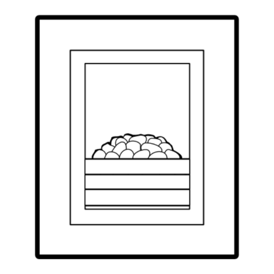
- Page 29 ADVANTAGE PLACEMENT OF CERAMICS - PEBBLE AND COAL Underbed MUST SIT BEHIND THESE TABS ON THE BURNER Front Piece 1. Locate the base of the front ceramic piece 2. Holding the underbed by the top rear, up against the brackets at the front edge, position it against the front ceramic piece.
- Page 30 ADVANTAGE PLACEMENT OF CERAMICS - DRIFTWOOD AND CHARCOAL Underbed MUST SIT BEHIND THESE TABS ON THE BURNER Front Piece 1. Locate the base of the front ceramic piece 2. Holding the underbed by the top rear, up against the brackets at the front edge, position it against the front ceramic piece.
- Page 31 PLACEMENT OF CERAMICS - SLAB 16 ONLY 2 Loose Outer pieces marked “X” on underside 10 Numbered Outer Clusters 7 10 Please note that the numbers given here are NOT NOT marked on the ceramic pieces. Place the numbered outer ceramic clusters into Ensure the outer ceramics are evenly spaced Ensure the outer ceramics are evenly spaced Ensure the outer ceramics are evenly spaced...
- Page 32 FAULT FINDING - POWER FLUE VERSION GENERAL OPERATION NOTES With the ON/OFF switch set to position 1 (ON) The most likely reason for the fire not to light the PCB checks that the air pressure switch is when the fan is working is a blown solenoid coil in the resting position and fan is turned on, due to a spike in the mains electricity supply.
- Page 33 COMISSIONING AND SERVICING COMISSIONING SERVICING Ensure all plastic protective films have been SLAB 16 - Carefully remove the outer ceramics removed. and place to one side. The SLAB 16 product requires commissioning to Carefully remove the burner ceramics and place be carried out prior to fitting the raised hearth.
- Page 34 [Blank]...
- Page 35 [Blank]...
- Page 36 LFL Group Limited Thwaites Close Blackburn BB1 2QQ England tel +44 (0)1254 682384 fax +44 (0)1254 672647 www.brilliantfires.co.uk info@brilliantfires.co.uk 30072009...
Need help?
Do you have a question about the ADVANTAGE and is the answer not in the manual?
Questions and answers