Table of Contents
Advertisement
Advertisement
Table of Contents

Subscribe to Our Youtube Channel
Related Manuals for Thomas & Betts Elastimold Molded Vacuum Reclosers

Summary of Contents for Thomas & Betts Elastimold Molded Vacuum Reclosers
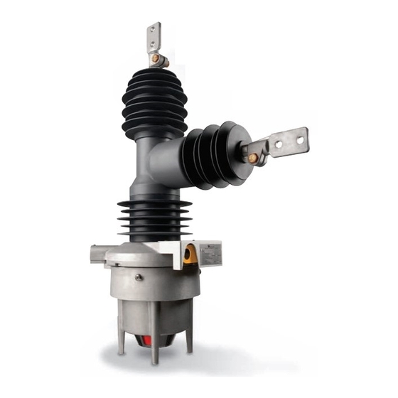
- Page 1 MVR Molded Vacuum Reclosers Instruction Manual...
-
Page 2: Introduction
Introduction Elastimold MVR Molded Vacuum Reclosers ® Thank you for your purchase of the Elastimold ® Molded Vacuum Recloser (MVR). This state-of-the-art recloser incorporates several design features that will assure you of many years of reliable, trouble-free service. Features and innovations include: A lightweight, maintenance-free, fully modular design allowing individual pole replacement or shed replacement in the... -
Page 3: Table Of Contents
Table of Contents Elastimold ® SECTION 1: Overview Introduction ................2–3 Ordering Information ..............4 Ratings and Specifications ............4 Description SECTION 2: Instruction Manual and Drawings Elastimold ® MVR Single-Phase and Three-Phase of Operation Instruction Manual .............5–12 Safety Instructions.............5 Acceptance and Inspection ..........6 The single-phase Elastimold ®... -
Page 4: Ordering Information
Ordering Information/Ratings and Specifications Molded Vacuum Recloser Catalog Numbering System MVR 3 15 12 3 2 Sequential Numbers Notes: Source-Side Phase ® 1 = One 15 = 15kV 12 = 12.5 kA = No 1 = SEL ® 351R, SEL ®... -
Page 5: Instruction Manual
Instruction Manual Safety Instructions The following are general caution and warning statements that apply to this equipment. Additional statements related to specific tasks and procedures are located throughout this manual. WARNING: CAUTION: Before installing, operating, When testing at high voltage, CAUTION: The complete recloser WARNING: WARNING:... -
Page 6: Acceptance And Inspection
Instruction Manual Acceptance and Initial Inspection Each MVR is shipped completely assembled, pretested and in the closed position from the factory. Upon arrival, uncrate the unit (refer to Crate Removal and Visual Inspection section). Check the unit does not have missing parts and it is in the closed position. -
Page 7: Set-Up And Mounting
Set-Up Before installing, operating, maintaining or testing this equipment, carefully read and understand the WARNING: contents of this manual. Improper operation, handling or maintenance can result in death, severe personal injury or equipment damage. Set-up and testing of the recloser Line can be performed at maintenance facilities, test laboratories or directly... - Page 8 Instruction Manual Mounting Note: Use extreme care in handling the recloser so that no force is exerted on the side terminals or on the individual poles as damage may result. 180˚ Attach the mounting bracket to the pole or structure using a ⁄...
- Page 9 Line Arrester Line Arrester LINE ARRESTOR LINE ARRESTOR Surge Arrester Mounting Each single-phase recloser mounting ring has a provision for mounting an optional bracket on either side of the recloser to support two customer-supplied arresters (one line-side and one load-side). Refer to the supplied recloser drawings for specific installation dimensions.
-
Page 10: Voltage Sensor Set-Up
Instruction Manual Electronic Operation Test Grounding Using the controller, open and close the MVR electrically by To ensure the maximum amount of protection for internal pressing the marked open and close buttons. Confirm that control components during possible power surge events, the selected button is in agreement with the position indicator the recloser and control cabinet need to be solidly grounded on the control panel as well as the recloser position indicator. - Page 11 Manual Trip Lever Test With the switch closed, pull down the yellow trip lever as shown in center photo at right and verify that the recloser opens. The position indicators located on the bottom of the recloser Closed Position will be GREEN for OPEN. The manual trip lever will remain in the down position until returned to the up position.
-
Page 12: Operation And Maintenance
Instruction Manual Operation Maintenance The recloser receives the CAUTION: The complete recloser system, including control, requires routine inspection necessary signal to open and and maintenance if damage is found to ensure proper operation. If it is not maintained, close from the control circuitry. it may fail to operate properly. -
Page 13: Outline Drawings
Outline Drawings Single-Phase 15/27kV... - Page 14 Outline Drawings Single-Phase 15/27kV...
-
Page 15: Single-Phase 38Kv - 3188C0111
Single-Phase 38kV... - Page 16 Outline Drawings Single-Phase 38kV...
-
Page 17: Three-Phase 15/27Kv - 3188C0112
Three-Phase 15/27kV... - Page 18 Outline Drawings Three-Phase 15/27kV...
-
Page 19: Three-Phase 38Kv - 3188C0113
Three-Phase 38kV... - Page 20 Outline Drawings Three-Phase 38kV...
-
Page 21: Schematic Drawings
Schematic Drawings Single-Phase 15/27/38kV... -
Page 22: Three-Phase 15/27/38Kv - 3118C0114
Schematic Drawings Three-Phase 15/27/38kV ELASTIMOLD MVR SEL 651R RECLOSER CONTROL THREE-PHASE RECLOSER SOURCE SIDE 32-PIN CONTROL CABLE SOURCE SIDE PHASE 1 VOLTAGE SENSOR SOURCE SIDE PHASE 2 VOLTAGE SENSOR SOURCE SIDE PHASE 3 VOLTAGE SENSOR SOURCE SIDE PHASE 1 CT PHASE 2 CT PHASE 3 CT CT RETURN... -
Page 23: Power Module (For Use With Sel ® 351R) - 3118C0116
Power Module (for use with SEL ® 351R) SEL 351R ELASTIMOLD ELASTIMOLD MVR THREE-PHASE RECLOSER RECLOSER CONTROL POWER MODULE SOURCE SIDE 14-PIN 32-PIN CONTROL CONTROL CABLE CABLE 24Vdc 24Vdc NOT USED MONITOR MONITORED TRIP NOT USED TRIP CIRCUIT POINT TRIP TRIP NOT USED COMMAND... -
Page 24: Elastimold Mvr Test Data Summary
Elastimold MVR Test Data Summary ® Elastimold ® MVRs are tested under the requirements of ANSI C37.60-2003. are certified as single-phase devices and are capable of single-phase tripping on all grounded and ungrounded circuits within their respective rated maximum voltages (17.1kV for 15kV units and 29.3kV for 27kV units).
Need help?
Do you have a question about the Elastimold Molded Vacuum Reclosers and is the answer not in the manual?
Questions and answers