
Related Manuals for AEMC 1060


Summary of Contents for AEMC 1060
- Page 1 ® Advanced Test Equipment Rentals www.atecorp.com 800-404-ATEC (2832) 10 50 MEGOHMMETER 10 60 E N G L I S H User Manual...
- Page 2 12 months and begins on the date of receipt by the customer. For recalibration, please use our calibration services. Refer to our repair and calibration section at www.aemc.com. Serial #: ________________________________ Catalog #: 2130.01 / 2130.03 Model #: 1050 / 1060 Please fill in the appropriate date as indicated:...
-
Page 3: Table Of Contents
1.4.2 Accessory Information ............6 Remote Test Probe ................6 DataView ® Software (Model 1060) ............6 Serial Printer (Model 1060) ..............6 Serial-to-Parallel Adapter (Model 1060) ..........6 2. PRODUCT FEATURES ..............7 Control Features ..................9 Digital Display Features ..............10 Bargraph ....................10 Symbols .....................11 Button Functions ................12... - Page 4 Insulation Measurement (see § 2.6.2)..........31 Continuity Measurement (see § 2.6.3) ..........32 Resistance Measurement (see § 2.6.3) ..........32 Capacitance Measurement ..............32 (Model 1060) ........... 33 5. MEMORY / RS-232 RS-232 Specifications ................33 Saving / Recalling Values (MEM/MR Button) ........33 Printing Measured Values ..............35 Instantaneous Printing of Measurements (PRINT button) ....36...
- Page 5 ® 7. USING DATAVIEW ................ 41 Features .....................41 Installing DataView ................41 ® Connecting the Model 1060 to your Computer ........45 Using DataView ® ................46 7.4.1 Configuring the Instrument............47 7.4.2 Running the Test ..............49 8. MAINTENANCE ................52 Battery Replacement (Model 1050) ...........52 Recharging the Battery (Model 1060) ..........52...
-
Page 6: Introduction
Risk of electric shock. The voltage at the parts marked with this symbol may be dangerous. In conformity with WEEE 2002/96/EC Megohmmeter Models 1050 /1060... -
Page 7: Definition Of Measurement Categories
file a claim immediately with the carrier and notify your distributor at once, giving a detailed description of any damage. Save the damaged packing container to substantiate your claim. NOTE: Charge the instrument fully before use (Model 1060). 1.4 Ordering Information Megohmmeter Model 1050.............Cat. #2130.01... -
Page 8: Accessories And Replacement Parts
Accessories and Replacement Parts Remote Test Probe ................Cat. #2118.97 Cable, PC RS-232, DB9 F/F 6 ft Null Modem Cable (1060)..... Cat. #2119.45 Replacement Cable (for Serial Printer) PC RS-232, DB9 F/F 6 ft ..Cat. #2119.46 Fuse, set of 5, 0.1A, 660V ..............Cat. #2119.56 Fuse, set of 1, 2.5A, 1200V .............. -
Page 9: Product Features
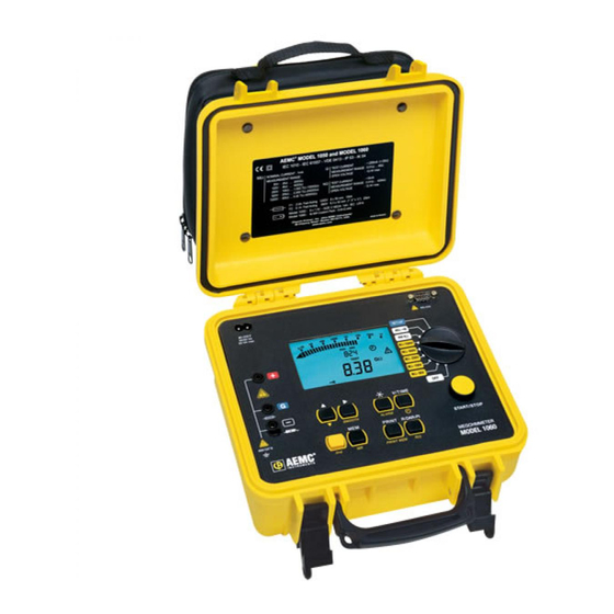
CHAPTER 2 PRODUCT FEATURES The Megohmmeters Models 1050 and 1060 are portable instruments housed in rugged casing. The Model 1050 uses 1.5V (C cell) alkaline batteries. The Model 1060 uses a rechargeable battery and AC power. These megohmmeters are designed to check the safety of electrical installations and equipment. - Page 10 MEM MR OBJ. TEST M - 500V M - 250V μA nA μF ALARM SMOOTH REMOTE M -100V M - 50V V/TIME SMOOTH ALARM START/STOP PRINT R-DAR-PI 600V CAT III MEGOHMMETER PRINT MEM R(t) MODEL 1060 Megohmmeter Models 1050 /1060...
-
Page 11: Control Features
SET-UP - Set-up of the megohmmeter START/STOP button Back-lit liquid crystal display 6 buttons (1050) or 8 buttons (1060), each with a first and second function. The second functions are highlighted in yellow below each button: • 2nd - Selects the second function on each button •... -
Page 12: Digital Display Features
• Elapsed time or the output voltage, during insulation measurement After recording data (1060), the small display also indicates the time and date in MR (memory recall) mode, and the memory address with the OBJ : TEST number. 2.3 Bargraph •... -
Page 13: Symbols
OBJ:TEST: Memory address (1060) - the number is displayed on the small digital display. COM: Flashes on the screen when data is transmitted to the serial interface (1060) or remains permanently displayed if there is a problem during transfer. DAR/PI: Indicates the mode chosen before insulation measurement or the results of these measurements. -
Page 14: Button Functions
MEM (memory storage) function. NOTE: If the selector switch’s position is altered, or if the STOP button is pressed during measurement, the measurement is interrupted. This function is only active for insulation measurement. Megohmmeter Models 1050 /1060... -
Page 15: R-Dar-Pi / R(T) Button
• Insulation resistance in MΩ, GΩ or TΩ. Automatic Measurement of DAR or PI: • If the button is pressed when in voltage measurement mode before pro- ceeding with a measurement, the following is displayed: Megohmmeter Models 1050 /1060... - Page 16 Model 1050: Up to 20 samples can be recorded during measurement at the sample rate chosen in SET-UP (the default value is 30 seconds). It is possible to save more than 20 samples depending on available memory. Megohmmeter Models 1050 /1060...
-
Page 17: Alarm Button
Press 2 & Alarm buttons repeatedly until you see the test you wish to set alarms for in the top line of the display. The sequencing will be 50, 100, 250, 500, 1000, Res and Cont. Megohmmeter Models 1050 /1060... -
Page 18: Smooth Button
Activates a digital filter for insulation measurement. It only has an effect on the displayed values (which are smoothed) and not the actual measurements. For example, this function is useful when the displayed insulation values are highly unstable, brought about due to a capacitive component in the tested element. Megohmmeter Models 1050 /1060... -
Page 19: Button
After having pressed a button, the corresponding figures or symbols appear on the screen • The figures or the symbols that can be modified flash on the screen • Use the buttons • All the parameters are immediately and permanently saved Megohmmeter Models 1050 /1060... - Page 20 ON / OFF (9th press) The values shown on this table, in the “Display/main” and “Display/small” columns, are the factory default values. In case they are accidentally changed, it is possible to get them back (see § 2.5.11). Megohmmeter Models 1050 /1060...
-
Page 21: Clearing The Memory
The resistance of the leads will be stored and indicated on the main display NOTE: • This value is stored in memory, even when the instrument is switched OFF. • The lead compensation only comes into effect when performing continu- ity measurements. Megohmmeter Models 1050 /1060... -
Page 22: Default Device Configuration
ON/OFF on the main display. • Choose ON or OFF using the button for each test voltage you wish to disable (OFF) or to reinstate (ON) for use during insulation tests at these voltages. Megohmmeter Models 1050 /1060... -
Page 23: Measurement Functions
If the measurements fluctuate greatly, the SMOOTH function can be enabled (see § 2.5.5). By pressing the V/TIME button during measurement, you can alternate between displaying the duration of the voltage measurement and the exact voltage gener- ated on the small display (see § 2.5.2). Megohmmeter Models 1050 /1060... -
Page 24: Continuity
flashes and the audible alarm beeps (for 2 seconds) signaling that the measurement was denied. The instrument then goes back to its normal voltage measurement. If the voltage is <3V and the START/STOP button is pressed, the measure- ment proceeds. Megohmmeter Models 1050 /1060... - Page 25 flashes and the voltage value is indicated on the small digital display. If the ALARM function is activated, a buzzer is triggered as soon as the measure- ment crosses the threshold programmed in the SET-UP configuration menu. Megohmmeter Models 1050 /1060...
-
Page 26: Specifications
“-” terminals. 660V between the “G” and “-” or “G” and “+” terminals. AC/DC Measurement Ranges: 50V: 2kΩ to 200GΩ 100V: 4kΩ to 400GΩ 250V: 10kΩ to 1TΩ 500V: 20kΩ to 2TΩ 1000V: 40kΩ to 4TΩ Megohmmeter Models 1050 /1060... - Page 27 Capacitance Measurement (following the discharging of test object): • Range: 0.005 to 4.999μF • Resolution: 1nF • Accuracy: ±10% ± 1ct Graphs showing the typical changes in test voltage as a function of the load: Resistance (k ) Megohmmeter Models 1050 /1060...
- Page 28 Resistance (k ) Resistance (k ) Resistance (k ) Megohmmeter Models 1050 /1060...
- Page 29 Discharge time of the tested element (across a 750kΩ internal resistance) up to 25V: Initial Voltage Discharge Time 1000V 2.8s 500V 2.2s 250V 1.7s 100V 0.5s Range of DAR and PI Ratios: 0.000 to 9.999 Accuracy: ± 5% Megohmmeter Models 1050 /1060...
-
Page 30: Continuity
Max. Voltage Surge: 1200V for 10 seconds between the “+” and “-” terminals AC/DC 660V between the “G” and “-” or “G” and “+” terminals AC/DC Max Serial Mode Voltage: ; measurement is prohibited above this value AC/DC Megohmmeter Models 1050 /1060... -
Page 31: Power Supply
100Ω 3.6 Power Supply • 8 x 1.5V (C cell) alkaline batteries; LR14 (Model 1050) • Rechargeable battery NiMH (Model 1060) • Recharge: 85 to 256V / 50-60Hz (electrical safety: 256V, Cat. III) Model 1050: Measurement: Average operating time Insulation Measurement:... -
Page 32: Mechanical Specifications
Immunity: NF EN 55 082 -1 (June 95) Mechanical Protection: IP 54 according to NF EN 60529 (Oct 92) IK 04 according to NF EN 50102 (June 95) *All specifications are subject to change without notice. Megohmmeter Models 1050 /1060... -
Page 33: Operation
CHAPTER 4 OPERATION NOTE: Charge the instrument fully before use (Model 1060). 4.1 Measurement Procedure • Start the instrument by selecting the corresponding position (MΩ, 40Ω or 400kΩ) with the selector switch. All the segments on the LCD screen are displayed, then the battery (or rechargeable battery) voltage is displayed. -
Page 34: Continuity Measurement (See § 2.6.3)
NOTE: The R-DAR-PI and V/TIME buttons are not active for this function. 4.5 Capacitance Measurement Capacitance measurement is automatically carried out during insulation measure- ment. It is displayed after the measurement is stopped and the circuit is discharged, using the R-DAR-PI button. Megohmmeter Models 1050 /1060... -
Page 35: Memory / Rs-232 (Model 1060)
Data format: 8 data bits, 1 stop bit, no parity, Xon / Xoff protocol. Connection to a PC or to a Parallel Printer Cable, PC RS-232, DB9 F/F 6 ft Null Modem Cable (1060)..... Cat. #2119.45 9-pin female connector 9-pin female connector... - Page 36 • If the entire memory is full, the arrow to the left of the bargraph flashes. • As soon as the storage is complete, the bargraph disappears. Each segment of the bargraph equals approximately 50 recordings. Megohmmeter Models 1050 /1060...
-
Page 37: Printing Measured Values
5.3 Printing Measured Values (PRINT/PRINT MEM Button - Model 1060) If you use a serial printer, choose the appropriate communication speed (com- munication rate) in the SET-UP menu, between 300...9600 communication, then program the printer to the format run by the instrument (see §... -
Page 38: Instantaneous Printing Of Measurements (Print Button)
Time Resistance Voltage 00 : 30 35.94 GOhm 1005V 01 : 00 42.00 GOhm 1005V 01 : 30 43.50 GOhm 1005V etc... A space for the operator’s signature is available at the end of the printout. Megohmmeter Models 1050 /1060... -
Page 39: Printing Data In Memory (Print Mem Button)
To stop printing, alter the position of the selector switch. Only the main results are printed out. Example : AEMC Instruments Model 1060 ® Instrument number: 000 001 CONTINUITY TEST OBJECT: 01 ........TEST: 01 Date: ..........03.31.2001 Start time: ..........14:55 Continuity: ..........0.45Ω Megohmmeter Models 1050 /1060... -
Page 40: Printing With The Serial-To-Parallel Adapter
PRINT after a measurement. • To start printing out saved measurements, press the PRINT MEM button WARNING: This adapter is designed exclusively for use with the Model 1060 and is not suitable for any other application. Megohmmeter Models 1050 /1060... -
Page 41: Application Examples
The measurements are performed between conductors or between all the con- ductors and the earth 6.2 Measurements on Electrical or Telecom Cable Braid Insulator Guard Cable Insulation between wires or between each wire and the earth. Megohmmeter Models 1050 /1060... -
Page 42: Insulation Measurements On Motors
6.3 Insulation Measurements on Motors Motor Motor coils Megohmmeter Models 1050 /1060... -
Page 43: Using Dataview
7.1 Features DataView has a simple, easy-to-use interface for configuring and running tests ® with the Model 1060, as well as, printing reports of the test results. There are many features that are available through DataView ® Key Features: •... - Page 44 Adobe Reader - Links to the Adobe website to download the most recent ® version of Adobe Reader to the computer. Adobe Reader is required for ® ® viewing PDF documents supplied with DataView that are accessible from ® the Help menu. Megohmmeter Models 1050 /1060...
- Page 45 .dmf or .emf files generated by DataView without having DataView ® ® software installed. • Software Updates - Links to the AEMC Software Update website to check ® for new software version releases. • Firmware Upgrades - Links to the AEMC Firmware Upgrade website to ®...
- Page 46 11. The Install Driver dialog box will appear. Click on Install. Figure 7-4 NOTE: The installation of the drivers may take a few moments. Windows may even indicate that it is not responding, however it is running. Please wait for it to finish. Megohmmeter Models 1050 /1060...
-
Page 47: Connecting The Model 1060 To Your Computer
7.3 Connecting the Model 1060 to your Computer The Model 1060 is supplied with a serial interface cable necessary for connecting the instrument to the computer. This cable (Cat. #2119.45) is equipped with a 9-pin female connector on each end, thus providing the ability to interface with comput- ers that have 9-pin connectors (see diagram in §... -
Page 48: Using Dataview
® 7.4 Using DataView Once the serial connection between the computer and the Model 1060 has been completed, as described above, start DataView ® There are two ways to open and use the DataView software: ® Using the Megohmmeter Icon •... -
Page 49: Configuring The Instrument
The Communication Rate will default to 9600 and should be acceptable to any computer. This is also the default rate for the Model 1060. You may select a different rate by clicking on the Communication Rate drop-down menu and selecting from the available values. - Page 50 Figure 7-7 This dialog box lets you configure every aspect of the Model 1060 megohmmeter. Each field in the dialog box is identical to the programmable features available from the instrument front panel itself. Refer to § 2.5 for a complete description of each configurable function.
-
Page 51: Running The Test
Save to Disk: Saves the current data to a file in the computer. • Configure: Returns to the megohmmeter Setup dialog box for configur- ing the instrument. • Download: Retrieves data from the memory of the megohmmeter for storage in the computer. Megohmmeter Models 1050 /1060... - Page 52 Once the test has been completed press the Save to Disk button to save the results of the test just completed to a disk drive in your computer. Name the file, then press the Save button. Megohmmeter Models 1050 /1060...
- Page 53 Template. In the Groups window of this dialog box, click on “megohmmeter” and in the Templates window click on “Megohmmeter 1060 Summary Report”. In the Step 2: Specify Database(s) window, the file you just saved and named should be visible. If this is the file you wish to generate a report from, click the OK button.
-
Page 54: Maintenance
CHAPTER 8 MAINTENANCE Use only factory specified replacement parts. AEMC will not be held responsible ® for any accident, incident, or malfunction following a repair done other than by its service center or by an approved repair center. 8.1 Battery Replacement... -
Page 55: Fuse Replacement
Do not use alcohol, solvents or hydrocarbons. 8.5 Storage If the instrument is not used for an extended time period (longer than two months), remove the battery and store separately (Model 1050). Megohmmeter Models 1050 /1060... -
Page 56: Repair And Calibration
Chauvin Arnoux , Inc. d.b.a. AEMC Instruments ® ® 200 Foxborough Boulevard Foxborough, MA 02035 USA Phone: (800) 343-1391 (508) 698-2115 Fax: (508) 698-2118 E-mail: techsupport@aemc.com www.aemc.com NOTE: Do not ship Instruments to our Foxborough, MA address. Megohmmeter Models 1050 /1060... -
Page 57: Limited Warranty
Limited Warranty The Megohmmeter Model 1050/1060 is warranted to the owner for a period of one year from the date of original purchase against defects in manufacture. This limited warranty is given by AEMC Instruments, not by the distributor from whom it was ®... - Page 58 Notes: Megohmmeter Models 1050 /1060...
- Page 60 10/09 99-MAN 100237 v19 ® ® Chauvin Arnoux , Inc. d.b.a. AEMC Instruments 15 Faraday Drive • Dover, NH 03820 USA • Phone: (603) 749-6434 • Fax: (603) 742-2346 www.aemc.com...
Need help?
Do you have a question about the 1060 and is the answer not in the manual?
Questions and answers