Furuno NX-700B Service Manual
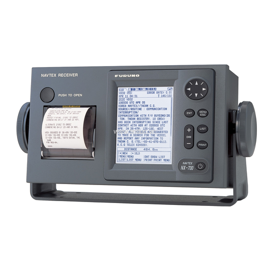
Navtex receiver
Hide thumbs
Also See for NX-700B:
- Operator's manual (89 pages) ,
- Specifications (2 pages) ,
- Gmdss manual (6 pages)
Table of Contents

Related Manuals for Furuno NX-700B


Summary of Contents for Furuno NX-700B
- Page 1 NAVTEX RECEIVER NX-700A/B Important; This manual is intended for use by authorized FURUNO service technicians for the installation of this equipment. Under no circumstances should the contents of this manual be released to the user.
- Page 2 The paper used in this manual is elemental chlorine free. FURUNO Authorized Distributor/Dealer FURUNO Authorized Distributor/Dealer 9-52 Ashihara-cho, 9-52 Ashihara-cho, Nishinomiya 662-8580, JAPAN Nishinomiya 662-8580, JAPAN Telephone : Telephone : 0798-65-2111 0798-65-2111 0798-65-4200 0798-65-4200 FIRST EDITION : FIRST EDITION : DEC.
- Page 4 This page is intentionally left blank.
-
Page 5: Table Of Contents
Contents Contents Setting and Checking Guide Chapter 1. Overview ・・・・・・・・・・・・・・・・・・・・・・・・・・・・・・・・・・・・・・・・・・・・・・・・・・・・・・ 1.1 Overview ・・・・・・・・・・・・・・・・・・・・・・・・・・・・・・・・・・・・・・・・・・・・・・ 1.1.1 Configuration ・・・・・・・・・・・・・・・・・・・・・・・・・・・・・・・・・・・・・・・・・・・・・・・・ 1.1.2 Installation ・・・・・・・・・・・・・・・・・・・・・・・・・・・・・・・・・・・・・・・・・・・・・・・・ 1.2 Operation Guide ・・・・・・・・・・・・・・・・・・・・・・・・・・・・・・・・・・・・・・・・・・・ 1.2.1 NAVTEX system ・・・・・・・・・・・・・・・・・・ 1.2.2 Auto mode: Automatic station selecting function ・・・・・・・・・・・・・・・・・・・・・・・・・・・・・・・・・ 1.2.3 Saving of NAVTEX message ・・・・・・・・・・・・・・・・・・・・・・・・・・・・・・・・・・・・・・・・・・・... - Page 6 Contents ・・・・・・・・・・・・・・・・・・・・・・・・・・・・・・・・・・・・・・・・・・・・・・・・ 2.2.2 Ver-01.02 2-13 ・・・・・・・・・・・・・・・・・・・・・・・・・・・・・・・・・・・・・・・・・ 1. Receiver Mode 2-13 ・・・・・・・・・・・・・・・・・・・・・・・・・・・・・・・・・・・・・・・・・・ 2. Local Channel 2-14 ・・・・・・・・・・・・・・・・・・・・・・・・・・・・・・・・・・・・・・・・・・・・・ 3. Auto Print 2-14 ・・・・・・・・・・・・・・・・・・・・・・・・・・・・・・・・・・・・・・ 4. Rcv Station & Msg 2-15 ・・・・・・・・・・・・・・・・・・・・・・・・・・・・・・・・ 5. User Select Station & Msg 2-15 ・・・・・・・・・・・・・・・・・・・・・・・・・・・・・・・・・・・・・・・・・ 2.3 Setting of System menu 2-16 ・・・・・・・・・・・・・・・・・・・・・・・・・・・・・・・・・・・・・・・・・...
- Page 7 2.8.1 Default setting of DIP SW 2-31 ・・・・・・・・・・・・・・・・・・・・・・・・・・・・・・・・・・・・・・・・・・ 2.8.2 Switch operation 2-31 Chapter 3. Parts Location ・・・・・・・・・・・・・・・・・・・・・・・・・・・・・・・・・・・・・・・・・・・・・・・・・・・・・ 3.1 NX-700A ・・・・・・・・・・・・・・・・・・・・・・・・・・・・・・・・・・・・・・・・・・・・・・・・・・・・・ 3.2 NX-700B ・・・・・・・・・・・・・・・・・・・・・・・・・・・・・・・・・・・・・・・・・・ 3.3 Receiver unit: NX-7001 ・・・・・・・・・・・・・・・・・・・・・・・・・・・・・・・・・・・・・・・・・・・ 3.4 Antenna unit: NX-7H 3-10 Chapter 4. Menu Tree ・・・・・・・・・・・・・・・・・・・・・・・・・・・・・・・・・・・・・・・・・・・・・・・・ 4.1 User Menu Tree ・・・・・・・・・・・・・・・・・・・・・・・・・・・・・・・・・・・・・・・・・・...
-
Page 8: Configuration
Contents Chapter 5. Block Description ・・・・・・・・・・・・・・・・・・・・・・・・・・・・・・・・・・・・・・・・・・・・・・・・・・ 5.1 Configuration ・・・・・・・・・・・・・・・・・・・・・・・・・・・・・・・・・・・・・・・・・・・・・・・・・ 5.1.1 NX-700A ・・・・・・・・・・・・・・・・・・・・・・・・・・・・・・・・・・・・・・・・・・・・・・・・・ 5.1.2 NX-700B ・・・・・・・・・・・・・・・・・・・・・・・・・・・・・・・・・・・・・・・・・・・・・・・・・・・・ 5.2 Connection ・・・・・・・・・・・・・・・・・・・・・・・・・・・・・・・・・・・・・・ 5.2.1 Overview of connection ・・・・・・・・・・・・・・・・・・・・・・・・・・・・・・・・・・・・・・・・・・・・・・ 1. NX-700A ・・・・・・・・・・・・・・・・・・・・・・・・・・・・・・・・・・・・・・・・・・・・・・ 2. NX-700B ・・・・・・・・・・・・・・・・・・・・・・・・・・・・・・・・・・・・・・ 3. Overview of boards ・・・・・・・・・・・・・・・・・・・・・・・・・・・・・・・・・・・ 5.2.2 Input/output specifications ・・・・・・・・・・・・・・・・・・・・・・・・・・・・・・・・・・・・・・・・・・・・ 1. Receiver unit ・・・・・・・・・・・・・・・・・・・・・・・・・・・・・・・・・・... - Page 9 Contents Chapter 7. Maintenance ・・・・・・・・・・・・・・・・・・・・・・・・・・・・・・・・・・・・・・・・・・・ Call up the Initialize menu ・・・・・・・・・・・・・・・・・・・・・・・・・・・・・・・・・・・・・・・・・・・・・・・・・・・・・・ 7.1 Self Test ・・・・・・・・・・・・・・・・・・・・・・・・・・・・・・・・・・・ 7.1.1 [MENU] -> Service -> Test ・・・・・・・・・・・・・・・・・・・・・・ 7.1.2 [MENU] -> Initialize 2 -> Serviceman Test ・・・・・・・・・・・・・・・・・・・・・・・・・・・・・・・・・・・・・・・・・・・・・・・ 7.1.3 Factory Test ・・・・・・・・・・・・・・・・・・・・・・・・・・・・・・・・・・・・・・・・・・・・・・・・・・ 7.2 Rcv Monitor 7-10 ・・・・・・・・・・・・・・・・・・・・・・・・・・・ 7.2.1 [MENU] ->...
- Page 10 Q20. The icon showing “during printing” is displayed ・・・・・・・・・・・・・・ in the Status field of NX-700B (not incorporating a printer). Q21. A new station starts operation. Is it needed to change the program or ・・・・・・・・・・・・・・・・・・・・・・・・・・・ circuit to receive messages from this station? ・・・・・・・・・・・・・・・・・・・・・・・・・・・・・・・...
- Page 11 Contents ・・・・・・・・・・・・・・・・・・・・・・・・・・・・・・・・・・・・・・・・・・・・・・・・ Specifications AP1-1 ・・・・・・・・・・・・・・・・・・・・・・・・・・・・・・・・・・・・・・・・・・・・・・・・・・・・・・・・・ Part List ・・・・・・・・・・・・・・・・・・・・・・・・・・・・・・・・・・・・・・・・・・・ Contents of Drawings...
- Page 12 This page is intentionally left blank.
- Page 13 Setting and Checking Guide Setting and Checking Guide 1. The following two operations are included as special operations: 1) How to call up option menu (Initialize1 and Initialize2 menus). Hold down both [+] and [-] keys of the DIM for over 5 seconds. Menu NAVTEX System...
- Page 14 Setting and Checking Guide 4. Can a message be received? If not, check the following points: 1) Is the power of +9 VDC applied to the antenna terminal of NX-7001? 2) Execute “[MENU] -> Service -> Test”. If the result of the Rx Test is OK, the problem is not with the Receiver unit.
- Page 15 - ITU-R M 540-2, M 625-3 The equipment configuration comprises an Antenna unit of the magnetic-field type NX-7H, a Receiver unit NX-7001, and either of two types of Display units NX-700A which incorporates an LCD and a printer or NX-700B as a discrete device.
- Page 16 - 12VDC: Max. 3 m 3D-2V: 10/20/40/50 m RECEIVER unit: RG10U: 30/40/50 m NX-7001 Max.100 m INS (GPS) IEC61162-1/2 (RS-485: Max.100 m) ALARM System Power (12 – 24VDC) 100/220 VAC AC/DC Power: PR-240-CE Serial Printer Fig. 1.1.2 Configuration of NX-700B...
-
Page 17: Installation
Fig. 1.1.3 Example of printing 1.1.2 Installation 1. Install the Display unit NX-700A or NX-700B at a place where the ship is normally navigated. 2. Input the ZDA sentence. Without the entry of the ZDA sentence, the time stamp on the header of printing and the reception time to be displayed in the reception list are shown blank. -
Page 18: Operation Guide
1.2 Operation Guide 1.2 Operation Guide 1.2.1 NAVTEX system Registered Information Providers Navigationnal Search and Rescue Meteorological Message Warning (SAR) Co-Ordinator Co-Ordinator Co-Ordinator NAVTEX Co-Ordinator NAVTEX Broadcast Station Service Area; 250 - 400nm Phasing signal ZCZC B1B2B3B4 Message NNNN >> 10s space + LF ZCZC B1 B2 B3 B4... - Page 19 1.2 Operation Guide In the NAVTEX system, stations allocation on the NAVAREA are divided into four groups (A-F, G-L, M-R and S-X). Each group has a capacity for broadcasting six times a day (every four hours) and at intervals of 10 minutes. Fig.
-
Page 20: Auto Mode: Automatic Station Selecting Function
1.2 Operation Guide 1.2.2 Auto mode: Automatic station selecting function When a position data is entered, the Auto mode can be used. The range of the selection is specified in “Area: nm” in the NAVTEX Station List of the Operator’s Manual. Note: The information on the service area of each station is extracted from the Cost station List issued by the ITU. -
Page 21: Saving Of Navtex Message
1.2 Operation Guide 1.2.3 Saving of NAVTEX message Received messages are saved in the memory (SRAM) which is backed up by a battery. 1. The number of messages that can be stored is up to 200 messages for the international frequency and the local frequency, respectively (The average number of characters of one message is 500). -
Page 22: Operation Guide
1.2 Operation Guide 1.2.4 Operation Guide 1. Status display Icon Status Meaning Shows that there is an unread message on the international frequency Blinking (518 kHz). Blinking Shows that there is an unread message on the local frequency (L1: 490 kHz, L2: 4209.5 kHz). Blinking Blinking Shows that a message is being received. - Page 23 1.2 Operation Guide GD65 ALL MESSAGE JAN 01 00:33 7 MESSAGE 7 MESSAGE ZCZC GD65 007 PA65 JAN 01 01:02 xxxxxxxxxxxxxxxxxxx 006 MB65 JAN 01 00:55 xxxxxxxxxxxxxxxxxxx 005 ME64 JAN 01 00:42 xxxxxxxxxxxxxxxxxxx 004 GD65 JAN 01 00:33 Scroll:[▲], [▼] 003 DC63 JAN 01 00:22 NNNN 002 AA65 JAN 01...
-
Page 24: User Display
1.2 Operation Guide 2. User display Date & Time display Related setting: Select [MENU] -> Display -> User Display -> Nav Data (ZDA data is displayed.) Position data display ALL MESSAGE Related setting: x MESSAGE Select [MENU] -> Display -> User Display ->... -
Page 25: Chapter 2. System Setting
Chapter 2. System Setting Overview Overview 1. To call up the Initialize menu The menu includes the Initialize1 and Initialize2 menus as option menus. These menus include special settings and items related to maintenance. To call up these menus, hold down both the [+] and [-] keys of the DIM for over 5 seconds on a screen on which the popup display is not shown and the received message list or received messages are shown. -
Page 26: Setup Guide
Overview 3. Setup Guide Configure the setting according to the needs of each user. This NX-700A/B receives NAVTEX messages in the default setting as it is. Basically, the NAVTEX, System, Display and Service menus are to be set by users. Do not attempt to change the settings of the Initialize1 and Initialize2 menus needlessly. - Page 27 Overview Menu Item Setting Remarks Page nm, kt Units km, km/h Unit display of Nav data Setting 2-18 mi, mi/h System None NX-700A Printer Type of connected printer setting 2-19 Upright Inverted Slow Scrolling Setting of scrolling 2-20 Fast Skip To $$ Small Setting of character size of received message Font Size...
- Page 28 Overview Table 2.3 Initialize Setup Guide Menu Item Setting Remarks Page 2-25 Delete All Msg Deletion of received message 7-15 All settings are reset to default settings and 2-25 All Clear received messages are deleted. 7-15 Demo Mode ON/OFF of Demo Mode setting 2-25 System Test 2-25...
-
Page 29: Nav Data
2.1 Nav data 2.1 Nav data Input position data such as GGA to enable the Auto mode. Input ZDA sentences of the Time/Date data to display the time of a received message. Table 2.1.1 Nav Data Data Sentence Time/Date Position GNS >... -
Page 30: Setup Of Nav Data Input
2.1 Nav data 2.1.1 Setup of Nav data input - [MENU] -> Service -> INS Input Speed (4800/9600/19200/34800) - [MENU] -> Initialize 2 -> Sumless NMEA (Receive/Ignore) INS Input Speed: Select the bit rate for serial data input of the Nav data. Sumless NMEA: Select whether or not to load a sentence with or without checksum. - Page 31 2.1 Nav data Nav data Checking: Select “Nav Data” in the setting of [MENU] -> Display -> User Display. Check that the position data and Date/Time data are displayed on the screen. To check whether Nav data is inputted, select [MENU] -> Initialize1 -> View Nav Data. See page 7-12 for details.
-
Page 32: Setting Of Navtex Menu 2.2.1 Program Ver-02.01
2.2 Setting of NAVTEX menu 2.2 Setting of NAVTEX menu 2.2.1 Program Ver-02.01 1. Mask Mode (INS/Manual) Select whether to set: Mask of “Rcv Mask” on the NAVTEX menu manually or by the command from the INS. To perform the setup manually, select “Manual”. In this case, the Mask set command from the INS is disabled but the Nav data such as the position data and Date/Time data are enabled. -
Page 33: Auto Rcv Mask
2.2 Setting of NAVTEX menu 2. Auto Rcv Mask (On/Off) This is the setting of On/Off of the Auto mode. See page 1-6 for the details of this function. This setting is enabled when “Manual” is selected in [MENU] -> NAVTEX -> Mask Mode. -
Page 34: Local Channel
2.2 Setting of NAVTEX menu 3. Local Channel (490kHz/4209.5kHz) This is the setting which local frequency, 490 kHz or 4209.5 kHz, should be received. When “INS” is selected in [MENU] -> NAVTEX -> Mask Mode, this setting item is not displayed. When “4209.5 kHz”... -
Page 35: Ins Output Mask
2.2 Setting of NAVTEX menu 5. INS Output Mask (Default: Receive All) This is the setting of the stations and message types to be outputted to the INS port. INS Output Mask [518] Station ABCDEFGHIJKLMNOPQRSTUVWXYZ Message ABCDEFGHIJKLMNOPQRSTUVWXYZ [490] (or [4209.5]) Station ABCDEFGHIJKLMNOPQRSTUVWXYZ Message... -
Page 36: Printer Mask
To print a received message, set this to other than “Off” in [MENU] -> System -> Printer. In case of NX-700A, set it to “NX-700A” and in case of NX-700B, set it according to the connected printer type (Invert or Upright). -
Page 37: Ver-01.02
2.2 Setting of NAVTEX menu 2.2.2 Ver-01.02 1. Receiver Mode (INS/Auto/Manual) This is the setting of operation mode of the NX-700A/B. Select “INS” for setting the local frequency, receiving stations and message types by the NMK sentence from the INS. When set to “INS”, - The setting item of [MENU] ->... -
Page 38: Local Channel
2.2 Setting of NAVTEX menu 2. Local Channel (490kHz/4209.5kHz) This is the setting which local frequency, 490 kHz of 4209.5 kHz, to be received. When to “INS” is selected in [MENU] -> NAVTEX -> Receiver Mode, this item is not displayed. -
Page 39: Rcv Station & Msg
2.2 Setting of NAVTEX menu 4. Rcv Station & Msg (Default: Receive All) This is the setting of the receiving stations and message types for 518 kHz and local frequency (frequency set in “Local Channel”), respectively. (Default: Receive All) Station ・... -
Page 40: Setting Of System Menu
L is received. This setting is linked with ON/OFF of the external alarm signal output. When an SAR message D is received, alarm beeps and an external alarm signal are outputted regardless of this setting. NX-700B NX-7001 J403 Normal Open... -
Page 41: Signal Monitor
2.3 Setting of System menu Table 2.3.1 Alarm Operation Received Program ALM beep How to stop alarm Msg. Version output 01.02 Stopped by pressing any key 1. Stopped by pressing any key Every second 2. Stopped by the sentence from the INS A or B or L ON/OFF Note:... -
Page 42: Time Offset
2.3 Setting of System menu 4. Time Offset (00:00) This is the time difference of the time display setting. The items reflecting the time difference are as follows. The setting is not applied to the time in the received message. 1) Received time display shown in the received message list display. -
Page 43: Printer
6. Printer (NX-700A/Upright/Invert/None) This is the setting of the printer type. Model NX-700B does not have a printer. To connect a printer, select a printer to meet the following specifications. The printer should be prepared by a user. - Serial printer... -
Page 44: Setting Of Display Menu
2.4 Setting of Display menu 2.4 Setting of Display menu Differences in the Display menu between the program Ver-01.02 and Ver-02.01 are the presence of the item “User Select Station & Msg”. - Ver-01.02 ! Included in the NAVTEX menu. - Ver-02.01 ! Included in the System menu. -
Page 45: Date Display
2.4 Setting of Display menu 4. Date Display (MMM DD YYYY/DD MMM YYYY/YYYY MMM DD) This is the type of the date display setting. The items reflecting the date display are as follows. This is not applied to the date in the received message. 1) Received date display in the received message list display (except “Year”... -
Page 46: Speed Display
2.4 Setting of Display menu Related setting: [MENU] -> Display -> Time Display [MENU] -> Display -> Date Display [MENU] -> System -> Unit 6. Speed Display (SOG/STW) This is the setting of the ship speed type of the Nav data display at the bottom of the received message screen. -
Page 47: Setting Of Service Menu
2.5 Setting of Service menu 2.5 Setting of Service menu The contents of the service menu are same for the programs Ver-01.02 and Ver-02.01. 1. INS Input Speed (4800/9600/19200/38400) This is the setting of the bit rate for serial data input of the INS port J402 of NX-7001 unit. -
Page 48: Edit Station List
2.5 Setting of Service menu 4. Edit Station List The NAVTEX station list can be edited. Stations can also be added or deleted. The maximum number of registered stations is 300 including the preset stations. Auto mode is performed on the basis of the position and range data (service area) of this list. -
Page 49: Setting Of Initialize-1 Menu
2.6 Setting of Initialize-1 menu 2.6 Setting of Initialize-1 menu The contents of the Service menu is same for the programs Ver-01.02 and Ver-02.01. 1. Delete All Msgs See page 7-15 for details. 2. All Clear See page 7-15 for details. 3. -
Page 50: Zczc Check
2.6 Setting of Initialize-1 menu 6. ZCZC Check (On/Off) This is the setting whether or not to receive a message when there is an error between ZCZC and the space after it. Always select “On”. - Off: When the error is not more than one character, the message is received. - On: If there is an error, the message is not received. -
Page 51: Available Rcv Station List
2.6 Setting of Initialize-1 menu 9. Available Rcv Station List This is the setting for displaying the list of receiving stations and message types that can be received by the setting in [MENU] -> NAVTEX -> Rcv Station & Msg or by the setting from the INS. -
Page 52: Setting Of Initialize-2 Menu
2.7 Setting of Initialize-2 menu 2.7 Setting of Initialize-2 menu Differences in the Initialize 2 menu between the programs Ver-01.02 and Ver-02.01 are the presence of the setting “Russia Mode”. - Ver-01.02 ! Russia Mode is present. - Ver-02.01 ! Russia Mode is not present. 1. -
Page 53: Dx Rx Decision
2.7 Setting of Initialize-2 menu 6. DX RX Decision (Soft/Hard) This is the setting whether to judge as a character error when there is a difference in the status of DX and RX of the NAVTEX signal. Always set this to “Soft”. Letter shift 1001100 1001100... -
Page 54: Russia Mode
2.7 Setting of Initialize-2 menu 8. Russia Mode (On/Off) This item is added in the program Ver-02.01. When this is set to “On”, the functions are changed to comply with Russia Type approval. Item Russia Mode On (Russia) Russia Mode Off (IEC) 1. -
Page 55: Setting Of Printer Μtp-58E-Fu
2.8 Setting of printer µTP-58E-FU 2.8 Setting of printer µTP-58E-FU 2.8.1 Default setting of DIP SW Do not change the configuration of DIP switches for setting the printer operation. DIP SW for operation setting Fig. 2.8.1 DIP SW Table 2.8.1 Default setting of DIP switches DIP SW Pin No. - Page 56 2.8 Setting of printer µTP-58E-FU Table 2.8.3 Functions of DIP switches Input DIP SW Pin No. Baud rate Parity method 38400 19200 9600 None 4800 2400 38400 19200 Serial 9600 4800 2400 38400 19200 Even 9600 4800 2400 Parallel Table 2.8.4 Functions of DIP switches DIP SW Pin No.
-
Page 57: Chapter 3. Parts Location
Chapter 3. Parts Location 3.1 NX-700A 3.1 NX-700A NX-700B µTP-58E-FU Fig. 3.1.1 Front view RECEIVER (25p D-Sub) GND Terminal Fig. 3.1.2 Rear view... - Page 58 3.1 NX-700A DIP SW; For Printer power Setting of Printer board installation Printer (µTP58E-FU) Fig. 3.1.3 Rear cover removed Printer Power board (08P3226) Fig. 3.1.4 Printer Power board...
- Page 59 3.1 NX-700A TP1(+) R20: Switching frequency ADJ (135 kHz + 1 kHz) Check: TP1 – TP2 TP1(-) Fig. 3.1.5 PWR (Printer Power board): 08P3226, side-A Fig. 3.1.6 PWR (Printer Power board): 08P3226, side-B...
- Page 60 3.1 NX-700A Printer (µTP58E-FU) Fig. 3.1.7 Panel cover removed DIP SW 1: OFF 7, 8 : OFF 2: ON : ON 3, 4, 5: OFF 10 : OFF 6: ON Fig. 3.1.8 Printer: µTP58E-FU...
-
Page 61: Nx-700B
3.2 NX-700B 3.2 NX-700B Fig. 3.2.1 Front view [RECEIVER ] port GND Terminal Fig. 3.2.2 Rear view and Side view... - Page 62 CPU board (08P3225) SRAM Back-up Jumper R79: V-ADJ (+12 VDC OUT ADJ.) R106: F-ADJ Switching power supply frequency Check: TP1 – TP2 Fig. 3.2.3 NX-700B Rear panel removed Beep for receiving monitor and key click Fig. 3.2.4 CPU board removed...
- Page 63 3.2 NX-700B Fig. 3.2.5 J2 disconnected Fig. 3.2.6 J1 disconnected...
-
Page 64: Receiver Unit: Nx-7001
3.3 Receiver unit: NX-7001 3.3 Receiver unit: NX-7001 Fig. 3.3.1 Receiver unit J401 (25p D-sub) J402 INS (GPS) Power input J403 (+12 to+24 VDC) ALM/Printer RCV board (08P3227) Fig. 3.3.2 Receiver unit cover removed... - Page 65 3.3 Receiver unit: NX-7001 For 518 kHz For 490 kHz R60: B-Y Duty 50 % ADJ R75: B-Y Duty 50 % ADJ F401 (2 A Fuse) For 490 kHz: Y301 (3.9064 MHz) J101 For 518 kHz: Y201 (RF IN) (4.1304 MHz) 490 kHz Xta’l FIL TP201 TP301...
-
Page 66: Antenna Unit: Nx-7H
3.4 Antenna unit: NX-7H 3.4 Antenna unit: NX-7H Fig. 3.4.1 NX-7H Pre-AMP Fig. 3.4.2 Upper cover removed 3-10... - Page 67 3.4 Antenna unit: NX-7H Fig. 3.4.3 Pre-AMP unit Fig. 3.4.4 Shield cover of Pre-AMP unit removed 3-11...
- Page 68 3.4 Antenna unit: NX-7H MF/HF Bar Antenna 1 Note: MF/HF Bar Antenna 2 The coil winding direction differs in Antenna 1 and Antenna 2. Fig. 3.4.5 Pre-AMP removed, and Bar Antenna 3-12...
-
Page 69: Chapter 4. Menu Tree
Chapter 4. Menu Tree 4.1 User Menu Tree The menu tree differs according to the program versions. - Ver-01.02 : Comply with IEC Standard - Ver-02.01 : Comply with Russian type approval 4.1 User Menu Tree 4.1.1 Program Ver-01.02 [MENU/ESC] NAVTEX Receive Mode (INS, Auto, Manual) Local Channel (490kHz, 4209.5kHz) -
Page 70: Program Ver-02.01
4.1 User Menu Tree 4.1.2 Program Ver-02.01 [MENU/ESC] NAVTEX Mask Mode (INS, Manual) Auto Rcv Mask (On, Off) Local Channel (490kHz, 4209.5kHz) Rcv Mask INS Output Mask Printer Mask System Warn Msg Alm (Off, On) Signal Monitor (Off, Int’l, Local) Key Beep (Off, On) Time Offset (-13:30 +13:30;... -
Page 71: Initialize1, 2 Menu Tree 4.2.1 Program Ver-01.02
4.2 Initialize1, 2 Menu Tree 4.2 Initialize1, 2 Menu Tree 4.2.1 Program Ver-01.02 Delete All Msgs [MENU/ESC] Initialize 1 All Clear Demo Mode (On, Off) System Test Results View Nav Data ZCZC Check (On, Off) 00 Msg Priority (00>B1>B2, B1>00>B2) Printer Order (Old ->... -
Page 72: Chapter 5. Block Description
Antenna unit, a Receiver unit and a Display unit. The Antenna unit NX-7H uses a magnetic-field type antenna. There are two types of display units: - NX-700A: LCD display unit (NX-700B) + printer incorporated (µTP-58-FU) + printer power supply - NX-700B: only LCD display unit (NX-700B) 5.1.1 NX-700A... -
Page 73: Connection
Fig. 5.2.1 Connection of NX-700A 2. NX-700B Receiver unit NX-7H (NX-7001) +12V J201 TEST RD-A/B FRQ RD-A/B (08P3227) 490 TD-A/B 518 TD-A/B RD-A/B TD-A/B 25p D-sub ALM-H/C RD(Printer) SD(Printer) J402 J403 TB401/401 DC IN ALM/Printer Fig. 5.2.2 Connection of NX-700B... -
Page 74: Overview Of Boards
The board outputs power +5.2 VDC from the input power (+12 VDC to +24 VDC). CPU (08P3225) The CPU board is incorporated in the LCD display unit (NX-700B). The board is comprised as follows. - CPU block (system control, handling NAVTEX signals: decodes BY signals sent from the RCV board, makes them up as received messages, and displays and stores them.) -
Page 75: Display Unit: Nx-700A/B
2. Display unit: NX-700A/B The specifications of the input/output of [RECEIVER] port of the Display unit: NX-700A incorporating a printer and the [RECEIVER] port of NX-700B including LCD unit alone are same, although SD/RD signals of #1 and #14 pins of the [RECEIVER] port on NX-700A are not connected. -
Page 76: Printer: Μtp-58E-Fu
5.2 Connection 518 RD-B +12 VDC GND ISO 23, 11, 24 DC + +12 VDC to +24VDC 12, 25, 13 DC - 3. Printer: µTP-58E-FU Pin No. Signal IN/OUT Function STROBE Data read (Active Low) 2 - 9 DATA 0 - 7 Data High: 1, Data Low: 0 Data input acknowledge signal (Active Low) BUSY... -
Page 77: Block Description
5.3 Block Description 5.3 Block Description 5.3.1 Receiver unit 1. RCV (08P3227) The receiving circuit is comprised of two systems to allow simultaneous reception at 518 kHz and 490 kHz or 4209.5 kHz. NAVTEX signals received from the antenna are separated into two circuits: BPF, Q1 circuit and BPF Q4 circuit. - Page 78 5.3 Block Description Signals received at 490 kHz Signals received at 490 kHz are switched at U1, inputted into RX2 circuit and converted into FSK signals of 1700 Hz + 85 Hz at U1 of this circuit. The local oscillator frequency (488.3 kHz) at U1 is generated by dividing the frequency Y1 (3906.5 kHz) by 8 at U2.
-
Page 79: Display Unit
5.3 Block Description 5.3.2 Display unit 1. CPU board (08P3225) The CPU board is comprised with CPU block and Power supply block. Main specifications of CPU block are shown below. Table 5.3.1 Main specifications of CPU block Item Specifications Set ID storage time One year or more (After power OFF) Number of stored IDs 200 x 2 channels... - Page 80 5.3 Block Description RESET n EEPROM Backup SRAM Reset (32kx8bits) (512kB) BATT RESET n Key scan Source DRAM KEY x 10 (512kB) Key scan Retrn Controller Back light Back light CR1/4/9/ Contrast 19/13/10 Printer SD/RD T/RxD 0 RS232C I/F RxD 2 INS TD-A/B, RD-A/B RS485 I/F TxD 1...
- Page 81 50 VDC and 0.5 A. The message A, B and L can be set to ON or OFF by the system setting. As for the message D, an alarm is always output when this message is received. NX-700B NX-7001 J403...
- Page 82 5.3 Block Description Power supply block The input voltage of +12 VDC to +24 VDC is converted to +18 VDC, +12 VDC, +5 VDC and +3.3 VDC on the switching power supply circuit. The main specifications are as follows. Table 5.3.3 Specifications of Power supply block Item Specifications Remarks...
-
Page 83: Pwr (08P3226)
5.3 Block Description 2. PWR (08P3226) The PWR board is a power supply board for the printer integrated in the Display unit of the printer-incorporating type NX-700A. It outputs +5.2 VDC from the power supply input of +12 VDC to +24 VDC. Main specifications are as shown in the table below. -
Page 84: Printer (Μtp-58E-Fu)
5.3 Block Description 3. Printer (µTP-58E-FU) The Printer unit µTP-58E-FU prints data inputted in the serial RS-232C mode by the thermal line-dot method. The dot density is 8 dots/mm and the maximum printing speed is 20 mm/sec. To connect a printer other than offered as the option, connect a printer meeting the following specifications. -
Page 85: Antenna Unit (Nx-7H)
5.3 Block Description 5.3.3 Antenna unit (NX-7H) The antenna (NX-7H) is a non-directional, magnetic field type antenna. The gain of this unit is approximately 10 dB at 518 kHz and 490 kHz, and approximately 20 dB at 4209.5 kHz. The circuit is comprised of two antenna coils and amplifier circuits for 4 MHz band and MF band. - Page 86 5.3 Block Description Reference; Letting the voltage magnitude (VA) induced in the antenna coil A in the direction of maximum sensitivity = “1”, VA=Sinθ Letting the voltage magnitude (VB) induced in the antenna coil B in the direction of maximum sensitivity = “1”, VB=Cosθ...
-
Page 87: Chapter 6. Program Update
6.1.2 Notices 1. The program update port is connected to #1 (SD), #14 (RD) and #22 (GND) of the [RECEIVER] port of NX-700B. The port is configured as RS-232C for electric specifications. 2. When the serial port on the PC side is specified as “other than [COM-1]”, rewrite the batch file or change the selection of the COM port to [COM-1] on the PC side. -
Page 88: Preparation
Do not connect the cable to this port. 25p D-sub Serial Port RECEIVER female #3-TXD #14-RD #2-RXD #1-SD NX-700B #5- GND #22- GND #11,23,24-DC(+) 9p D-sub #12,13,25-DC(-) female DC Power (+12 - +24VDC) Fig. 6.1.1 Connection for updating NX-700 Program... -
Page 89: Procedure For Rewriting Com Port Of Batch File
6.1 Overview 2. Procedure for rewriting COM port of batch file 1) Open [Control Panel] -> [System] -> [Device Manager] and check the COM port number on “USB - RS-232C Driver”. 2) Select a batch file to be updated and open the batch file by clicking [File] -> “Edition”. -
Page 90: Procedure For Updating
6.2 Procedure for updating 6.2 Procedure for updating 6.2.1 Procedure 1. Turn off NX-700B (LCD display unit). 2. Open the NX-700 program folder. 3. Double click the batch file “UP”. 4. When the DOS-prompt window appears and the message “TARGET POWER ON” is displayed, turn on NX-700. - Page 91 LCD. 6. When updating is complete, the normal display appears on the LCD. The time for updating is 3 to 4 minutes. 7. Turn off NX-700B once and return the connection as it was.
-
Page 92: Check Of Program Number
6.2 Procedure for updating 6.2.2 Check of program number 1. Hold down both the [+] and [-] keys of the DIM for over 5 seconds on ascreen on which the popup display is not shown and the received message list or received messages are shown. -
Page 93: Chapter 7. Maintenance
Chapter 7. Maintenance 7.1 Self Test Call up the Initialize menu The Initialize menu includes the Initialize1 and Initialize2 menus as option menus. These menus include special settings and items related to maintenance. To call up these menus, hold down both [+] and [-] keys of the DIM for over 5 seconds on a screen on which the popup display is not shown and the received message list or received message is shown. - Page 94 7.1 Self Test Memory Test 2. The memory test starts and the results of the test are shown. Memory Test Program No : 08501193-01 Boot : BOOTPGN-00 : OK SRAM : OK DRAM : OK CPU RAM : OK EEPROM : OK Battery : OK (3.3V) Hit any key...
- Page 95 7.1 Self Test Key Test 3. When the Memory test is complete, press any key. The next Key Test starts. The screen shown below appears. A mark corresponding to the pressed key is highlighted every time a key is pressed. Check all the keys except the power key. When all the keys are highlighted, or when no key is pressed for 10 seconds, the next LCD Test is entered.
- Page 96 7.1 Self Test If the “Result” is “NG”, replace the RCV board. In the reception test, messages received at 518 kHz only can be printed by a printer. Rx Test Tx Test ZCZC AZBB <- |T HIS IS AN I NTERNAL TES T MESSAGE.<-|ABCDEFGHIJKLMNOPQRSTUV WXYZ,0123456789 - ? * $ ! &...
-
Page 97: Menu] -> Initialize 2 -> Serviceman Test
7.1 Self Test 7.1.2 [MENU] -> Initialize 2 -> Serviceman Test Procedure 1. Select “[MENU] -> Initialize 2” and execute “Serviceman Test”. Start serviceman test ? (Print will be canceled.) Yes No Memory Test 2. The Memory Test screen is displayed as shown below. Check the program number, memory and voltage of backup battery. -
Page 98: Factory Test
Receiver1 : OK Receiver2 : OK Hit any key Table 7.1.1 Sections to be Jumpered for Loop-back Test Test item Model Sections to be jumpered NX-700B : NX-700A #1 (SD) - #14 (RD) [RECEIVER] Printer NX-7001: J403 NX-700B #4 (SD) - #5 (RD) - Page 99 7.1 Self Test Contrast Test 5. In the Contrast Test, the contrast of the screen automatically changes in 10 levels as shown below. The screen displays the result of the contrast test last. If the test result is “Pass”, press the [ENT] key three times, and if the result is “Fail”, press the [PRINT] key three times to proceed to the next Dimmer Test.
- Page 100 7.1 Self Test Alarm Buzzer Test 8. A continuous alarm beep is outputted in the test. If the test result is “Pass”, press the [ENT] key three times, and if the result is “Fail”, press the [PRINT] key three times and proceed to the next Contact Signal Test.
- Page 101 7.1 Self Test Output Test Results 11. If any key other than the power key is pressed, the results of the Factory Test are outputted to the printer. Output Test Results Connect PC. Hit any key to send. Related information: The factory test results are displayed by selecting “System Test Results”...
-
Page 102: Rcv Monitor
7.2 Rcv Monitor 7.2 Rcv Monitor This section describes information on monitoring of received signals. To monitor a received signal on audio frequency, Select “Int’l (518 kHz)” of “Local (490 kHz or 4209.5 kHz)” in “[MENU] -> System -> Signal Monitor”. To output monitor sounds, internally created audio frequency is outputted if the received signal component has frequency component above 1700 Hz. - Page 103 7.2 Rcv Monitor 518 kHz INT’L blink. ZCZC AB12 2408 UTC AUG 05 JAPAN Blinks when synchronized to the NAV**X N.W synchronizing signal broadcasted 490 kHz or 4209.5 kHz before ZCZC. Select the frequency in - ←: CR (Carriage return) “[MENU] ->...
-
Page 104: Test In Initialize-1 And Initialize-2 Menus
7.3 Test in Initialize-1 and Initialize-2 menus 7.3 Test in Initialize-1 and Initialize-2 menus 7.3.1 Test in Initialize-1 menu 1. System Test Results The System Test Results show the results of the factory test described in page 7-6. Normally, all the results are shown as “OK”. The test results are stored in U13 (EEPROM) and not cleared even if “All Clear”... -
Page 105: Adjust Rx Unit
7.3 Test in Initialize-1 and Initialize-2 menus 3. Adjust Rx Unit Dot signals of 1700 Hz + 85 Hz and 100 bps are applied to the RCV board and adjustments are made on the receiving FSK detection circuit (U4, 5: NJN221). The section to be adjusted is VR shown below. -
Page 106: Tests In Initialize-2 Menu
7.3 Test in Initialize-1 and Initialize-2 menus 7.3.2 Tests in Initialize-2 menu 1. Serviceman Test See page 7-5 for details. 2. Fill Memory This test is used for the Type approval test. When “Fill Memory” is executed, the memory area of messages is 100 % filled. Do not carry out this test on board. -
Page 107: Memory Clear
7.4 Memory Clear 7.4 Memory Clear This section describes information on clearing memory. 1. [MENU] -> Service -> Default Setting This setting restores the user setting menu to the default, except “Edit Station List” in “[MENU] -> Service” menu. However, received messages are not deleted. Select “[MENU] ->... - Page 108 7.4 Memory Clear 4. Items to be cleared Items that can be cleared in operations 1, 2 and 3 described previous page are as follows. All Clear Delete All Msgs Items to be cleared Default Setting operation operation operation [Menu] -> NAVTEX [Menu] ->...
-
Page 109: Popup Message
7.5 Popup Message 7.5 Popup Message When a certain event occurs, a user is notified of it on the popup massage display. Table 7.5.1 Popup message list of handling of Received message Popup of handling of received Description message This popup message is displayed when a new message is received on the local frequency (490 kHz or 4209.5 kHz). - Page 110 7.5 Popup Message In reception on the local frequency; 1. When “Alarm Message (A/B/D/L)” is selected on the [LIST] menu and an emergency message (ID = xx00) other than an alarm message is received. 2. When “Nondisplay” is selected for the station or received message in “[MENU] ->...
- Page 111 7.5 Popup Message Table 7.5.2 Printer and Battery error popup list Printer & battery error popup Description Printer error Displayed when paper runs out or the printer door is open. Printer error Related setting; Printer setting [MENU] -> System -> Printer Displayed when the voltage of the backup battery of the CPU board goes down below +2.5 VDC.
-
Page 112: Replacement Of Battery
7.6 Replacement of Battery 7.6 Replacement of Battery Replace the battery of the CPU board when is displayed in the Status display field. When the battery is replaced, all the backed-up received messages are cleared. But the user-programmed menu settings are not cleared. Reference: 1. -
Page 113: Troubleshooting
7.7 Troubleshooting 7.7 Troubleshooting 1. The power is not turned on. The power is not turned on. The over voltage protection circuit or Is the input power supplied at the rated low voltage protection circuit is activated. voltage of +11 VDC to +31VDC? Supply the power of the rated voltage. -
Page 114: Reception Trouble-1) No Reception
7.7 Troubleshooting 2. Reception trouble-1) No reception Check it in the following setting. - Ver-02.01 No reception [MENU] -> NAVTEX -> Mask Mode -> Manual - Ver-01.02 [MENU] -> NAVTEX -> Receiver Mode -> Manual 1. Check the cable between the Receiver unit and the Display unit. -
Page 115: Reception Trouble-2) There Are Many Reception Errors
7.7 Troubleshooting 3. Reception trouble-2) There are many reception errors. Check it in the following setting. ・Ver-02.01 There are many reception errors. [MENU] -> NAVTEX -> Mask Mode -> Manual ・Ver-01.02 [MENU] -> NAVTEX -> Receiver Mode -> Manual To check a receiving message in real time: [MENU] ->... -
Page 116: Nmea Data Is Not Inputted From The Gps
7.7 Troubleshooting 4. NMEA data is not inputted from the GPS. NMEA data is not inputted from the GPS. The connection ports are #4 (RD-A) and #5 Is the NMEA port connected properly? (RD-B) of the INS port J402 on NX-7001. Set the input speed at 4800 bps in Can NMEA data be monitored? “[MENU] ->... -
Page 117: The Printer Does Not Operate
1. Short-circuit between J403-#4 and #5 on NX-7001. 2. Turn the power on with the [+] and [-] keys held down. 3. Execute the Loop-back Test. 1. Check the cable between NX-7001 and NX-700B Replace the printer. 2. Failure of the CPU board 7-25... - Page 118 Chapter 8. Q & A Chapter 8. Q &A Q1. Can the FAX-5 antenna unit be used with NX-700A and B? It can be used in terms of electric characteristics. However, since the requirements for the Type approval of NX-700A and B include the Antenna unit NX-7H, the FAX-5 antenna cannot be used with NX-700A and B.
- Page 119 1) Check the input sentence. The acceptable sentences are ZDA, GNS, GGA, RMC, GLL, VTG, VBW and VHW. 2) Is the sentence inputted to NX-700A and NX-700B added with a checksum? Sentences with a checksum are those of NMEA Ver-2.0 or later, or IEC61162.
- Page 120 Q19. A received message cannot be printed. (2-19) Check the setting of “[MENU] -> System -> Printer.” Select “NX-700A” for the type NX-700A. In case of type NX-700B, configure the setting according to the specification of the printer. Q20. The icon showing “during printing”...
- Page 121 Chapter 8. Q &A Q21. A new station starts operation. Is it needed to change the program or circuit to receive messages from this station? (2-24) Stations can be edited by addition, deletion and change, etc. in the setting of “[MENU] ->...
- Page 122 Appendix 1. Specifications Appendix 1. Specifications 1. NAVTEX RECEIVER Receiving frequency 518 kHz and 490 kHz (or 4209.5 kHz), receive both frequencies simultaneously Mode of reception 2 µV e.m.f. (50 ohms), 4 % error rate or less Sensitivity Input protection Withstands 30 Vrms for 15 minutes or more (w/ pre-amp unit) Spurious emission 1 nW or less...
- Page 123 Appendix 1. Specifications 3. PRINTER SECTION 3.1 Printing system Line thermal head printing system 3.2 Printing paper Thermal paper (58 mm x 30 m) 3.3 Printing width 48 mm 3.4 Character format 24 x 12 dot 3.5 Dot pitch 8 dots/ mm 3.6 Number of characters 32 characters/line 3.7 Print speed...
- Page 124 Appendix 1. Specifications 7.3 Waterproofing - Antenna unit IP66 - Receiver / Display unit IP20 7.4 Vibration 2 Hz to 5 Hz and up to 13.2 Hz with a deviation of ±1 mm ±10 % (7 m/s maximum acceleration at 13.2 Hz); above 13.2 Hz and up to 100 Hz with a constant maximum acceleration of 7 m/s 8.
- Page 125 D−1...
- Page 126 D−2...
- Page 127 Contents of Drawings Name Type Dwg. No. Page ― NX-700A/B C5649-C01 Interconnection Diagram ― Display unit NX-700A C5649-K01 ― Display unit NX-700B C5649-K02 ― NX-7001 C5649-K04 RCV board 08P3227-1/2 C5649-K05 RX1, RX2 08P3227-2/2 C5649-K06 08P3225-1/4 C5649-K07 08P3225-2/4 C5649-K08 CPU board...
- Page 128 S−1...
Need help?
Do you have a question about the NX-700B and is the answer not in the manual?
Questions and answers