Table of Contents
Advertisement
Quick Links
Advertisement
Chapters
Table of Contents

Related Manuals for Avidyne Entegra


Summary of Contents for Avidyne Entegra
- Page 3 Revision History Rev Number Date of Release Reason for Release April 2009 Initial Release of document that coincided with Software Release 9.0.0 June 2009 Release of document that coincided with Software Release 9.0.1 September 2009 Release of document that coincided with Software Release 9.0.2 June 2010 Release of document that...
-
Page 4: Table Of Contents
Entegra Flight Display System | Release 9 PILOT GUIDE TABLE OF CONTENTS System Overview ..............1-2 FUNCTIONAL OVERVIEW ............1-2 BASIC CONCEPTS ..............1-3 REDUNDANCY ................1-9 MODULAR DESIGN ..............1-10 DATABUS ...................1-10 HARDWARE MODULARITY ............1-10 SOFTWARE MODULARITY ............1-12 DISPLAY ENHANCEMENTS .............1-12 AIRCRAFT CONFIGURATION MODULE ........1-13 HOW TO USE THE REST OF THIS MANUAL ......1-13... - Page 5 USE OF VECTORS MODE ............5-31 SYNTHETIC VISION ..............5-32 TERRAIN AWARENESS (SV-TA) ..........5-36 Arrivals/Approaches/Landing ..........6-2 ENROUTE DESCENTS ..............6-2 ENTERING AN ARRIVAL AND APPROACH .......6-4 USE OF THE SPLIT PAGES ............6-7 USE OF APPROACH CHARTS............6-9 FLYING AN AUTOPILOT COUPLED APPROACH ......6-9 USE OF THE TIMER ..............6-15 TAXI CHARTS ................6-16 Diverts/Missed Approaches ..........7-2 MISSED APPROACH ..............7-2...
- Page 6 MAIN 11-2 DISPLAY ..................11-3 11-4 MAP 11-5 DATABLOCKS................11-5 AUTOPILOT ................11-6 12 System Updates ............. 12-2 DATA UPDATES ................12-2 DATALOGS DOWNLOAD ............12-5 SOFTWARE UPDATES .............12-7 13 Release 7/8 to Release 9 Differences ......13-2 Appendix A – PFD ..............1 SETTING UP THE S-TEC 55X AUTOPILOT ......... 16 Appendix B –...
- Page 7 System Overview ..............1-2 FUNCTIONAL OVERVIEW ............1-2 BASIC CONCEPTS ..............1-3 Page Function Keys ................1-3 Line Select Keys ................... 1-4 Display Formats ..................1-5 ADI Upper Half ..................1-6 Primary Navigation Source ..............1-6 Full Alpha-numeric keyboard with display ..........1-6 Live Edits…...................
-
Page 8: System Overview
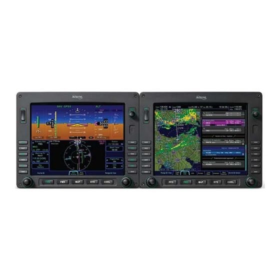
1 System Overview FUNCTIONAL OVERVIEW The Avidyne Entegra Release 9 flight display system supports the following functions: • Primary Flight Display • Flight Management System • SBAS GPS Navigation • VHF Radio Nav/Com • Attitude and Air Data Sensors • Moving Map •... -
Page 9: Basic Concepts
Avidyne strongly believes in the concept “Fly like you train and train like you fly”. In other words, the same views used on a daily basis are identical to what is available during emergency and reversionary conditions. -
Page 10: Line Select Keys
and navigate through the available tabs by pressing the left or right side of the Page Function Key. Continue pressing one side of the function key to automatically step through the tabs. Page Function Keys and Tabs LINE SELECT KEYS Line Select Keys, typically abbreviated to LSK in this manual, are the buttons found along the left and right sides of the bezel. -
Page 11: Display Formats
COOL FEATURE Addressable Line Select Keys On any given page only LSKs that can perform the labeled function are backlit. Keys that are non-functional are intentionally unlit. This is to visually “quiet” the display, reduce time searching for a desired button and also minimize extra pilot actions caused by inadvertently pressing the wrong button. -
Page 12: Adi Upper Half
ADI UPPER HALF The system has been configured to recognize in which position each display is located in the cockpit. This means that the PFD will always display an ADI on the upper half of the display, regardless of which page function keys are pressed along the bottom of the bezel. -
Page 13: Live Edits
The keypad is a QWERTY layout with a few special function buttons along the outer edges and a row of number keys along the top of the keypad. Just above the keypad is a display that is split into two distinct areas: a semi-permanent display of the com and nav frequencies on the left half of the display and a set of user-configurable datablocks in the right half. -
Page 14: Overlays
OVERLAYS The system supports overlays of data controlled via the LSKs. Examples on the Map pages include being able to turn on or off: • Datalink NOWrad weather displays • Datalink Icing displays • FIS-B Weather displays • AIRMETS/SIGMETS • METAR flags •... -
Page 15: Redundancy
Avidyne-compatible PS Engineering PMA8000B Audio Select Panel, the PFD displays the frequency and station identifier of the active com frequency just below the VSI in the primary field of view. The integration with the DFC100 autopilot is a tighter integration than previous display-autopilot integrations. -
Page 16: Modular Design
This system was designed to be modular; modular in the overall architecture, hardware, software and from a packaging perspective. This approach produces future extensibility and provides Avidyne with flexibility in adapting the system to meet future needs. DATABUS One of the key modularity components employed in this system is the databus. - Page 17 module may be replaced with an updated one. This enables an easy upgrade path for existing aircraft in the field. The hardware modules have considerable unused processing, memory and communication bandwidth allowing for maximum functional expansion without changing the existing hardware. In many cases, software upgrades may be accomplished without removing units from the aircraft.
-
Page 18: Software Modularity
In the single ADAHRS configuration, the ADAHRS is physically housed in the left IFD and the right IFD has an empty slot for the missing LRU. The attitude and air data from the single ADAHRS is still capable of being displayed on all IFDs. The FMS400 is still a full-featured FMS but does not support precision SBAS approaches (LPV), airways nor drop down options for arrivals and departures. -
Page 19: Aircraft Configuration Module
The use of any 3 party screen protector, especially those that adhere directly to the IFD display glass, is not endorsed by Avidyne and may void the warranty for any display related issue. AIRCRAFT CONFIGURATION MODULE An Aircraft Configuration Module (ACM) stores all aircraft-specific avionics configuration information. - Page 20 All images contained in this manual are for reference use only, and are subject to change. Avidyne strongly recommends that pilots use the Entegra Integrated Flight Display Release 9 System only under VFR conditions until completely familiar with its operation and use.
- Page 21 Normal Startup Sequence ..........2-2 SYSTEM POWER ................2-2 BRIGHTNESS CONTROLS ............2-2 STARTUP INDICATIONS .............2-2 Normal Startup Sequence...
-
Page 22: Normal Startup Sequence
2 Normal Startup Sequence SYSTEM POWER The IFDs and keyboard will automatically start when the aircraft bus power is applied. After power application, the keyboard display will be visible as well as the Brt/Dim rocker key on the IFDs. Several seconds later, the IFD displays will begin to have indications. - Page 23 While early taxi is permitted prior to alignment for flexibility, Avidyne highly recommends that the aircraft remain stationary until the alignment of all AHRS are complete and the alignment boxes are replaced by the ADI.
- Page 24 In dual Air Data and Attitude Reference System (ADAHRS) equipped systems, each IFD ADAHRS aligns independently. Therefore, it is recommended that each ADAHRS is verified to have aligned prior to taxi or takeoff by either checking the PFD tab of each IFD, or noting the CAS messages or checking the Sensor tab of the SYS page.
- Page 25 Ground Operations ............3-2 ELECTRONIC CHECKLIST ............3-2 ENTERING A FLIGHT PLAN ............3-3 FMS Basic concepts ................3-3 Creating A New Flight Plan ..............3-4 Activating A Flight Plan ................. 3-6 Saving/Naming A Flight Plan..............3-6 Copying A Flight Plan ................3-7 Inverting A Flight Plan ................
-
Page 26: Ground Operations
3 Ground Operations This section covers cockpit tasks that are typically performed during ground operations. Included are input of the local altimeter setting, performing start, taxi, and pre-takeoff checklists, proper monitoring of the engine and electrical systems, entering intended flight plan into the FMS and setting up the autopilot, radios and transponder in order to begin your flight. -
Page 27: Entering A Flight Plan
ENTERING A FLIGHT PLAN Ground operations are the ideal time to enter the intended flight plan into the FMS. Enter your plan into only one of the IFDs. The data is automatically shared between them. FMS BASIC CONCEPTS Each leg of a flight plan has its own color-coded background designed to make the overall flight plan easier to read at a glance. -
Page 28: Creating A New Flight Plan
Insert Cursor Edit Cursor Individual fields within a leg can be edited by rotating the “FMS” knob that highlights each editable field within the flight plan. When the desired field is highlighted with reverse video, push the “FMS” knob to get into edit mode. Turn the knob as required to edit the value or type via the keyboard, then push the knob again to exit edit mode. - Page 29 Flight Plan COOL FEATURE Geofill™ is a geographic-based prediction algorithm that significantly reduces the number of pilot actions for entering waypoints. Usually after the first character entry, the system uses existing characters to determine the closest, and most likely, waypoint based on your geographic position or existing flight plan.
-
Page 30: Activating A Flight Plan
origin. There are a number of flight plan legs out of sight below the bottom of the display. COOL FEATURE Expanding and Compacting the Flight Plan The “Flight Plan” tab of the FMS page provides a means to show every leg of the flight plan (“Expanded”) or an abbreviated version of the flight plan (“Compact”) via the “View”... -
Page 31: Copying A Flight Plan
Saving a Flight Plan COPYING A FLIGHT PLAN From the “Routes” tab of the “FMS” page, first select the route you wish to copy via the right-hand knob then press the “Copy” LSK on the right side of the bezel. This will present the route name in reverse video. -
Page 32: Use Of The Engine Tab
USE OF THE ENGINE TAB The engine tab of the SYS Page Function Key is designed to provide all necessary engine, electrical and related system information to enable safe operations. This page is commonly used during engine start and before takeoff run-up operations. Note that some aircraft do not display engine data on the IFDs. -
Page 33: Setting Up The Radios And Transponder
“COM 1” function key within a maximum of 10 seconds. For those aircraft equipped with the PS Engineering PMA8000B or the Avidyne AMX240 audio select panel, the keyboard will time out to the same "COM x" function key as the active radio on the audio select panel. -
Page 34: Transponder Mode And Code Input Via The Keyboard
COOL FEATURE Active Com Freq Decoded on PFD For those systems using an Avidyne-compatible PS Engineering PMA8000B or Avidyne AMX240 Audio Select Panel, the active frequency of the selected com radio will automatically be decoded and displayed on the PFD below the VSI indicator. This... -
Page 35: Sending A Nav Frequency To A Remote Dme
will automatically become the active transponder value after a few seconds or press the “Enter” button on the keypad. Transponder mode, IDENT and VFR functions all have their own dedicated function keys on the keyboard. The transponder mode will automatically toggle to “ALT” on takeoff roll when a specific groundspeed is achieved and back to Standby or Ground on landing. -
Page 36: Setting Up The Autopilot
VOR even if it doesn’t have a co-located DME. SETTING UP THE AUTOPILOT Avidyne recommends setting up your autopilot target bugs before takeoff. The keyboard has a dedicated knob along the bottom edge for Altitude and another for Heading. The DFC100 has a dedicated knob for Indicated Airspeed and another for Vertical Speed. - Page 37 Setting up the Autopilot Designed primarily for speed, the keyboard knobs for Heading and Altitude have several useful behaviors. Rotating the knobs results in coarse control of that bug. For example, coarse control for Altitude means that each click of the Altitude knob changes the Altitude bug incrementally by 500’.
-
Page 38: Taxi Charts
Verify the autopilot is initialized as indicated by the “AP READY” annunciation on the PFD. If there are plans to use the autopilot in flight, per the DFC100 Pilot Guide, an autopilot pre-flight test should be conducted. Setting the Altitude Bug TAXI CHARTS World-wide airfield diagrams are provided via the “Charts”... -
Page 39: Altimeter Setting
ALTIMETER SETTING On any IFD that is currently displaying an ADI, the dedicated “Baro” knob along the right edge of the bezel can be used to set the system barometric altimeter correction. Regardless of which IFD the baro setting is entered on, all IFDs will automatically receive the input. - Page 41 Departure…................4-2 DEPARTURE PROCEDURES .............4-2 VSPEEDS ON ASI ................4-5 ENGINE INDICATION ON ADI .............4-5 Departure Summary ................4-6 Departure 4-1...
-
Page 42: Departure
4 Departure DEPARTURE PROCEDURES If your origin has a published departure, that procedure can be loaded into the FMS flight plan. It can then be coupled to the autopilot for either automatic flight guidance or flight director guidance. The image below shows an example of a published departure being selected in the flight plan. - Page 43 COOL FEATURE Frequency List Pressing the “Freq List” function key on the keyboard will present a list of the most logical frequencies for your geographic position and phase of flight. If there isn’t an active flight plan the list will use the nearest airport frequencies. The “FMS”...
- Page 44 HSI view (“ND” tab) on the PFD, non-North Up map pages, and on the traffic thumbnail on all datablock format pages. Avidyne recommends selecting a datablock tab on the MFD. This ensures a dedicated traffic thumbnail is visible in a usable manner, no matter what the map range on the HSI or map page may be set to.
-
Page 45: Vspeeds On Asi
VSPEEDS ON ASI Under high power conditions, the V labels are shown at the correct airspeeds for the Best Angle of Climb ) and Best Rate of Climb speed (V speed (V ). V and V are adjusted based on density altitude, as described in the Airspeeds for Normal Operations section of your aircraft Pilot Operating Handbook. -
Page 46: Departure Summary
Manifold Pressure Fuel Flow Oil Temperature Oil Pressure Supplemental Engine Data on PFD DEPARTURE SUMMARY Your flight plan will automatically activate on departure roll, your transponder will automatically transition out of Ground (mode-S) Standby (mode-C) and into Alt mode and as soon you engage the autopilot, all mode transitions will automatically follow the FMS flight plan. - Page 47 COOL FEATURE Range to Altitude Indication A small green arc will be drawn on the map that depicts the geographic point where, at the current vertical speed, the aircraft will reach the altitude target (Alt Bug value). It will be removed from the map when current aircraft altitude is within 150’...
- Page 49 Cruise / Enroute ..............5-2 NAVIGATIONAL SITUATIONAL AWARENESS ......5-2 PRECISION FLYING ..............5-3 ENGINE LEANING ...............5-5 USE OF THE MAP ...............5-6 FMS OPERATIONS ..............5-9 USE OF NEAREST FUNCTION ..........5-18 DATALINK WEATHER OPERATIONS ........5-19 ON-BOARD WEATHER RADAR ..........5-28 AUTOPILOT OPERATIONS ............5-31 USE OF VECTORS MODE ............5-31 SYNTHETIC VISION ..............5-32 TERRAIN AWARENESS (SV-TA) ..........5-36 Cruise / Enroute...
-
Page 50: Cruise / Enroute
A number of aids have been included in this system to assist your navigational situational awareness. Note: Do not rely upon the Entegra Integrated Flight Display System as your sole source for navigational data or terrain/obstacle avoidance. Use the Entegra Release 9 as a supplement to current charts and other navigation and terrain avoidance sources. -
Page 51: Precision Flying
HEADING HORIZON TICK MARKS A series of heading indicators can be displayed along the horizon line of the ADI marking every 30 degrees. Cardinal directions are indicated by the letters N, E, S, W. The display of heading on the ADI can be turned on or off via the Display Setup tab. - Page 52 ALTITUDE ALERTING The altitude alerter provides an approach alert (“APPROACHING SEL ALT”) when the aircraft altitude is within the approach limit (typically 1000') of the selected altitude. The approach alert includes approach limit and a highlighting of the selected altitude. At this point the altitude alerter considers the selected altitude to be captured and the deviation alert is armed.
-
Page 53: Engine Leaning
current rate of turn. The indicator is marked for ½ and full standard rate of turn. An arrowhead indicates a value beyond 1 ½ standard rate. Deviations from the intended bank angle are easy to notice with the wide horizon line. USING TREND INDICATORS Use the trend indicators to capture and maintain a desired airspeed and altitude by adjusting the pitch and/or power to the... -
Page 54: Use Of The Map
Engine Leaning USE OF THE MAP The map has several formats and views. On the MFD, pages allow both a full map depiction as well as a datablock map depiction. In both cases, you have the ability to control the map feature density as well as the various overlays, all via the LSKs along the right edge of the bezel. - Page 55 future legs beyond the next leg will be depicted in white. Turning the right-hand bezel knob (inner or outer ring) will result in a map range change. Pressing the knob cycles through the various map views. The map view selected is indicated at the top of the map next to the heading box.
- Page 56 around the map and enables useful tasks such as panning ahead along your route, and determining bearing and distance of any object from your present position. Pop-up boxes offer information about an area of interest. Keyboard Map Panning Joystick These “hot spots” are all over the map and include every depicted Navaid, airport, and airspace, including TFRs.
-
Page 57: Fms Operations
Exit panning mode by either pushing the panning joystick or letting it automatically time out, which is approximately 20 seconds after the last joystick input. COOL FEATURE Fuel Range Ring The green fuel range ring depicted on the map provides a visual indication of the max range of the aircraft, allowing a 45-minute reserve. - Page 58 Notice an automatic curvature of the dashed Vectors line as it builds an “on-ramp” back to your solid magenta active leg line. Note: Never use the Entegra Integrated Flight Display System to penetrate severe weather such as thunderstorms or cells. Avoid severe weather areas with a safe margin of distance.
- Page 59 INSERTING A WAYPOINT From any tab where the flight plan is displayed (e.g. “FMS” Page on PFD, “FPL” tab of FMS Page on MFD), a new waypoint can be inserted. Use the “FMS” knob on the keyboard to scroll up or down the flight plan until the insert cursor is positioned where the new waypoint is to be inserted.
- Page 60 Vertical Constraint Fields The only waypoints that do not permit vertical constraints are: • Origin • Destination, provided there is an approach loaded for it • Missed Approach Point • Altitude Terminated Legs CREATING A USER WAYPOINT There are 4 methods of creating a user waypoint from the “User Wpts”...
- Page 61 Each user waypoint can be assigned a 5 character identifier that can be used in the FMS anywhere a nav database waypoint can be used. A longer description can also be attached to each user waypoint. ENTERING AND INTERCEPTING A RADIAL From the “Nav Display”...
- Page 62 Vectors mode may be used in conjunction with Course mode. A To or From course can be intercepted on a selected heading using Vectors mode. DELETING A FLIGHT PLAN Select the “Routes” tab of the FMS page. By pressing the “Delete Current”...
- Page 63 Direct-To Technique 2 There is also a Direct-To (-D->) LSK on most of the FMS tabs (Flight Plan, Info, User Waypoints, Nearest). Press the corresponding LSK, the green Direct-To dialog displays. Options are the same when using the -D-> on the keyboard. Canceling a Direct-To is as easy as placing the edit cursor over the Direct-To waypoint of interest and pressing the “Delete Waypoint”...
- Page 64 the drop down list. Scroll up or down the dropdown list as required and push one of the knobs to insert a hold flight plan leg. DELETING A HOLDING PATTERN To delete a holding pattern in your flight plan, use the “FMS” keyboard knob or the right MFD knob to scroll as required to create an edit cursor surrounding the holding leg, then press the “Delete Hold”...
- Page 65 Procedure Turn with Course Reversal FLIGHT PLAN SEQUENCING The FMS assumes that the pilot will fly the flight plan as defined. If that does not occur, legs may not sequence as expected. Therefore, to manually sequence the desired leg, select it and press “Activate Leg”.
-
Page 66: Use Of Nearest Function
waypoint. Otherwise, the leg before the Gap will not be sequenced and guidance will not be provided to the next waypoint. If desired, close the gap by placing the cursor on it. Press the CLR key or the R5 LSK on the Flight Plan tab, “Connect <wpt1>... -
Page 67: Datalink Weather Operations
TAFs and US RADAR. Product availability depends on the level of WSI subscription chosen. Note: Avidyne does not control, review, or edit the information made available by WSI, and is therefore not responsible for the accuracy of that information. - Page 68 The Datalink radar is a composite image depicting precipitation as seen by multiple ground-based weather radar sites. The image is color-coded to show intensity levels and precipitation types. Weather Data Legend (Broadcast WSI Weather) At large map ranges beyond 250nm from the aircraft, small areas of high-intensity NOWRad returns may not be displayed;...
- Page 69 US ADS-B WEATHER (FIS-B DATALINK) The FIS-B link is a transmission to your aircraft via a ADS-B network receiver. FIS-B Datalink is a subscription free product provided from the FAA and the receiver receives weather data when in range of an ADS-B ground station. You can control display of the received data on the various moving map pages.
- Page 70 “Off” turns those layers off from display). Note that when there is an on-board lightning sensor selected (Avidyne TWX670 Tactical Weather System or L3 WX500 Stormscope), the “Lightning” key becomes a split labeled LSK. The left side of the LSK is the “Clear Strikes” function and the right side of the LSK is used to change the source between onboard Datalink or Off.
- Page 71 Icing and Lightning LSKs Lightning Key Splits to Clear Strikes and Lightning Strike WEATHER REPORTS (FIS-B AND BROADCAST DATALINK) The “Wx Reports” key provides a means to control display of other weather-related data on the Map. The choices include “METARS”, “AIR/SIGMETS”, “All”, “Off”. •...
- Page 72 Graphical Metar Legend • AIRMETs and SIGMETs (US only) – These are areas which the National Weather Service has issued advisories for various types of hazardous weather. They are depicted on the Map page along with an abbreviated description of the hazard, such as “ICE” (icing), “MTN” (mountain obscuration), or “IFR”...
- Page 73 COOL FEATURE METAR Flags in Flight Plan The right edge of each leg in a flight plan presents a METAR flag for the closest reporting station, if the station is different from the previous leg’s station. The station for which the METAR flag applies is decoded immediately beneath the flag and may not be exactly the same location as the leg itself.
- Page 74 TEXTUAL DISPLAY OF TFRS INDICATIONS OF DATA AGE As noted above, there are multiple products that are transmitted as part of the ADS-B network and Broadcast Datalink. They can come in at different rates and so to provide an easy to use indication of data age, two indications are provided at the bottom of each map.
- Page 75 indicated on the display. Pilots should consider this potential delay when using in-cockpit weather received via the two networks and its capabilities, as the movement and/or intensification of weather could adversely affect safety of flight. Data Age: Metars and Icing Data Age: SYS Page, Sensor Tab TEXTUAL ADS-B WEATHER AND AIRSPACE INFO In addition to the graphical display of TFRs and...
-
Page 76: On-Board Weather Radar
Wx Products: Info tab IMPORTANT NOTE Winds and Temperature Aloft Winds and temperatures aloft depicted are only displayed as a 6 hour forecast. It is strongly recommended for the pilot to obtain the latest information through other approved sources for their operation. The 12 and 24 winds aloft forecast will need to be obtained via other approved sources. - Page 77 Forward View, Weather Radar Profile View, Weather Radar There is even a capability to overlay the weather radar image on top of the moving map display. Cruise / Enroute 5-29...
- Page 78 Weather Radar Overlay on Moving Map Controls exist to display forward or profile views along with adjusting the search volumes (range) azimuth and tilt angles. In addition, there are controls for tuning stabilization on/off and adjusting the radar mode. Radar Controls 5-30 Cruise / Enroute...
-
Page 79: Autopilot Operations
AUTOPILOT OPERATIONS While all modes of the DFC100 are available, Avidyne recommends maximizing use of the FMS and autopilot NAV and VNAV mode combination and let the automation reduce your workload. The top edge of the ADI will continually present annunciators that reflect the current state and mode of the autopilot. -
Page 80: Synthetic Vision
IMPORTANT NOTE Pilots should never use the Entegra Integrated Flight Display System to penetrate severe weather such as thunderstorms or cells. Avoid severe weather areas with a safe margin of distance. If the Primary Nav selection is set to FMS the “Fly Vectors” LSK on the PFD will need to be pressed to enter Vectors mode. - Page 81 PFD Synthetic Vision Scene The TVV is a visual representation of the aircraft flight path – it indicates where the airplane is going, and not necessarily where the aircraft is pointing. Terrain Awareness (SV-TA) and Forward Looking Terrain Alerting (FLTA) alerts are provided via terrain coloration, Caution-Warning Alerting System (CAS) alerts, and aural alerts.
- Page 82 selection carries through for all pages/tabs on the selected IFD where attitude is displayed in the upper half. SynVis On/Off Toggle Control on Nav Display Tab The 3D traffic uses the same symbology as that in the traffic thumbnails and map overlays but the traffic depictions in the SynVis scene attempt to indicate relative threat level by size and symbol and are depicted at the relative altitude and bearing as received from the traffic sensor, consistent with the SynVis field of...
- Page 83 Any airfield that is in the FMS database and in the SynVis field of view will be depicted in the SynVis scene with a METAR looking gray flag until the airfield is within 1.5nm at which time, the flag is removed and the runway outlines should be clearly visible.
-
Page 84: Terrain Awareness (Sv-Ta)
Obstacle Threat Bubbles The TVV will grow in size when it is behind the airspeed, altitude or heading digital readout bubbles in order to see be viewable. TERRAIN AWARENESS (SV-TA) SV-TA is for general situational awareness purposes and consists of hatched terrain on the SynVis scene and any map page. SV- TA will not generate a CAS message or aural alert. - Page 85 SV-TA can be triggered by either terrain or obstacles. Any terrain that is within a 10nm radius of aircraft position and between 100’ below aircraft altitude and 1000’ below aircraft altitude will generate yellow hatched indications on the SynVis scene and the map pages. Any terrain that is within a 10nm radius of the aircraft position and is 100’...
- Page 86 via a LSK on the PFD Nav Display tab. When turned off, there is no terrain SV-TA display on the SynVis scene nor the map pages for entire set of IFDs. Terrain Awareness (SV-TA) On/Off Controls There is a rectangular suppression area for all runways in the FMS database.
- Page 87 Runway Suppression Area Depiction FORWARD LOOKING TERRAIN ALERTING (FLTA) FLTA alerting is triggered by either a projected imminent impact with terrain or obstacle or reduced terrain and obstacle clearance. Projected imminent impact with terrain occurs when the TVV is projected to intersect with terrain up to 3.0nm (yellow caution) or up to 1.5nm (red warning) in front of the aircraft flight path.
- Page 88 Either terrain or obstacles can trigger FLTA alerts and they are distinguished via the CAS messaging and aural alerting. The difference between FLTA warnings and cautions is exclusively based on distance-to-go to projected impact points or reduced clearance areas. The projected imminent impact location or the projected reduced terrain and obstacle clearance area is depicted on the SynVis scene and the maps with a solid yellow (caution) or red (warning) “flashlight”...
- Page 89 FLTA Alert Depictions Each unique FLTA alert will generate a new Master Caution lamp illumination, a new CAS message, a new aural alert, and display the elliptical solid yellow/red coloration on the SynVis scene and maps. Each unique FLTA alert can be acknowledged by pressing the “Mute”...
- Page 90 area will not generate any FLTA alerts. Dimensions of the FLTA runway suppression area are 2.0 nm laterally and 4.0 nm off each runway end when runway orientations are known or a circle with a radius of 1 nm centered on the Airfield Reference Point (ARP) when the on-board databases do not know the runway orientations.
- Page 91 SynVis scene and on the map pages. Avidyne recommends the use of the default 45 degree field of view for most situations. Avidyne highly recommends using the default 45 degree field of view setting and/or the autopilot when attempting to capture discrete pitch settings or when flying approaches.
- Page 93 Arrivals/Approaches/Landing ..........6-2 ENROUTE DESCENTS ..............6-2 ENTERING AN ARRIVAL AND APPROACH .......6-4 USE OF THE SPLIT PAGES ............6-7 USE OF APPROACH CHARTS............6-9 FLYING AN AUTOPILOT COUPLED APPROACH ......6-9 PRECISION APPROACHES ............6-10 NON-PRECISION APPROACHES ..........6-10 BACK COURSE APPROACHES ..........6-10 SBAS APPROACHES ..............6-11 USE OF THE TIMER ..............6-15 TAXI CHARTS…….
-
Page 94: Arrivals/Approaches/Landing
6 Arrivals/Approaches/Landing Arrivals/Approaches/Landing Avidyne recommends that you enter the arrival and approach for the destination airfield, and alternates into the FMS flight plan. Selecting a published arrival and/or approach will automatically load the procedure including all altitude constraints into the FMS900w. - Page 95 Once the descent has begun, the Vertical Speed Required (VSR) cue on the Vertical Speed Indicator (VSI) can be used. VSR Green Diamond COOL FEATURE Vertical Speed Required When a vertical constraint has been added to the flight plan for the next leg, a green VSR cue is drawn on the VSI.
-
Page 96: Entering An Arrival And Approach
ENTERING AN ARRIVAL AND APPROACH This section only applicable for FMS900w: From any tab where the flight plan is capable of being edited, use the “FMS” knob on the keyboard to scroll up or down the flight plan as required until the edit cursor surrounds the waypoint that a published arrival and/or approach is to be entered. - Page 97 COOL FEATURE (FMS900W ONLY) FMS Preview A FMS Preview mode is available on the Map-FPL tab of the FMS page. As soon as changes start to be made to the FMS flight plan while on that tab, the map will revert to North- Up and stop displaying terrain.
- Page 98 Procedures Brackets COOL FEATURE (FMS900W ONLY) PROC button The “PROC” function key on the keyboard acts as a shortcut for attaching a published arrival or approach procedure to a waypoint in your flight plan. It can be used at any time.
-
Page 99: Use Of The Split Pages
knob on the IFD to scroll up or down the list until the desired procedure is selected then push that knob in to add that procedure to the flight plan. If there is no flight plan, then pressing the “PROC” function key will present the “Flight Plan”... - Page 100 graphical depiction on the map. This aids in error reduction and helps visually see options for diverts, weather avoidance, etc. COOL FEATURE Hot Links to Charts in Flight Plan Whenever a flight plan leg (blue airfield legs) has at least one published approach associated with it, a chart icon is presented on the right edge of the flight plan leg.
-
Page 101: Use Of Approach Charts
USE OF APPROACH CHARTS The system is typically loaded with IFR Approach charts (not Enroute charts) that can be accessed via the hot links to charts method just described or via the Charts or Charts + tabs on the Map page. If an approach has already been defined in the FMS flight plan, the Charts tabs will present the selected approach for the designated airfield. -
Page 102: Precision Approaches
CDI deflection will be driven by the localizer signal itself, regardless of the course setting. The HDI and VDI will automatically display on the ADI when the appropriate localizer and glideslope signals are received. Automatic mode switching (Primary Nav source and autopilot) will occur if the primary nav frequency can be auto-identified. -
Page 103: Sbas Approaches
ensure the Primary Nav LSK has selected “Nav1” or “Nav2” and the front course value is set via the Course Set knob (left hand IFD knob). Alternatively, if the published back course approach is entered into the FMS, all of the above is done automatically. As soon as the system determines that it is established on the back course localizer, the HDI source label indicates “LOC BCRS”... - Page 104 This is essentially the same as a non-SBAS GPS approach. It is flown as any other non-precision approach – observing step down restrictions, descend to MDA, fly at MDA altitude to the MAP;, and execute the missed approach procedure if appropriate. Since there is no vertical guidance associated with this type of approach, the VDI is not displayed.
- Page 105 LNAV/VNAV (Lateral Navigation with Vertical Navigation) In this mode, the GPS provides lateral navigation, providing more accurate guidance than regular LNAV but easier to follow indications than a localizer. The vertical navigation is driven by GPS signals. LNAV/VNAV approaches are operationally different from LNAV+V in that the glide path is protected from obstructions but attention still must be applied to step down fixes.
- Page 106 COOL FEATURE PFD L5 LSK Think of the L5 LSK on the PFD as your “hook” into the FMS. The button changes functionality based on the phase of flight or instrument procedure you are on. This provides a short cut to accomplish actions per the table below. L5 LSK Label Comments Only appears when the Primary Nav LSK is set to...
-
Page 107: Use Of The Timer
Continue/Exit Displayed when the active leg of the flight plan is a hold and is not the last leg of the route. Hold Displayed when the aircraft is within 5 nm of the FAF Skip Hold and the next leg is a database procedure hold. Pressing the LSK will sequence the active leg past the hold without entering it when the aircraft reaches the FAF. -
Page 108: Taxi Charts
will pick up where it was “frozen” and keep counting up from there. In every case, pressing “Reset” will take the timer back to 00:00 and start counting from there. TAXI CHARTS If a published procedure was used via the Charts tab for the landing airport, the display chart will automatically switch over to the airfield diagram during post-landing roll out. - Page 109 Diverts/Missed Approaches ..........7-2 MISSED APPROACH ..............7-2 RETRY APPROACH ..............7-3 Diverts / Missed Approaches...
-
Page 110: Diverts/Missed Approaches
7 Diverts/Missed Approaches MISSED APPROACH The simplest and safest way to properly fly a published missed approach is to ensure it is part of the active flight plan. It can be activated anytime inside the FAF by pressing the L5 LSK on PFD that is labeled “Enable Published Missed”. -
Page 111: Retry Approach
Published Missed Approach A recommended technique for executing the published missed approach procedures is as follows: Ensure the published missed approach is part of the active FMS flight plan Press “Enable Published Missed” L5 LSK when sequencing FAF At the point when you decide to go missed, add power as required After the aircraft is cleaned up, go-around power applied and climb-out attitude established, if not already done so, press the... - Page 113 Night Operations ...............8-2 IFD DISPLAY BRIGHTNESS ............8-2 IFD BEZEL BRIGHTNESS ............8-2 KEYBOARD DISPLAY BRIGHTNESS .........8-2 KEYBOARD BEZEL BRIGHTNESS ..........8-2 CHARTS LIGHTING SCHEME .............8-2 DISPLAY OF TERRAIN ON MAP ..........8-3 Night Operations...
-
Page 114: Night Operations
8 Night Operations There are several controls to assist selection of the proper and usable brightness level for night operations. IFD DISPLAY BRIGHTNESS Each IFD individually controls its own display brightness through the use of the manual BRT/DIM rocker key on the top left edge of the bezel. -
Page 115: Display Of Terrain On Map
“Land” part of the map declutter LSK to deselect terrain from being displayed. Note: Always refer to current aeronautical charts for appropriate terrain and obstacle information. Do not rely on the Entegra Integrated Flight Display System as your sole source of obstacle and terrain avoidance information. - Page 117 System Alerts ..............9-2 CAS SYSTEM................9-2 MISCOMPARES ................9-6 CROSSCHECK MONITOR ............9-8 System Alerts...
-
Page 118: System Alerts
9 System Alerts CAS SYSTEM A full caution-warning alerting system (CAS) has been included in this system. There are three levels of message alerting: • Warnings – Immediate action should be performed • Cautions – Immediate attention should be applied •... - Page 119 WARNING-CAUTION-ADVISORY MESSAGE BAR Two message bars are provided on every non-primary IFD to alert the pilot to what the CAS message is/are. Advisories are displayed on a cyan (blue) background in the lower left corner of each IFD. Warnings are displayed on red background in the lower right corner of each non-primary IFD.
- Page 120 The IFDs remain synched so that each shows the same set of Warnings, Cautions and Advisories. Acknowledging a state on one IFD, will “ack” it for all IFDs. COOL FEATURE Switch Tank Alert An optional timer can be set up to alert you at a fixed period (e.g.
- Page 121 ALERTS TAB Sometimes, there isn’t a good page (e.g. Engine tab for RPM exceedence) to change to when the “Show” side of the LSK has been pressed. In those cases, the “Alerts” tab of the SYS page is presented. This tab can also be manually selected at any time via the page and tab structure along the bottom edge of each IFD.
-
Page 122: Miscompares
MISCOMPARES The IFDs share and compare much of their data for fault detection purposes. If a miscompare occurs, both IFDs will display the appropriate warning message adjacent to the affected instrument. The following parameters are constantly being compared: • Pitch (Dual ADAHRS systems only) •... - Page 123 If the indications are outside the IFR limits, an alert message is annunciated on both IFDs. Miscompares In the event a miscompare is annunciated, Avidyne highly recommends diligence in crosschecking all on-board data sources. A pitch or roll miscompare will disconnect the DFC100 autopilot.
-
Page 124: Crosscheck Monitor
IFD. Crosscheck Attitude Alert In the event a “CROSSCHECK ATTITUDE” message is present, Avidyne strongly recommends scanning all backup instruments and auxiliary instruments (backup attitude indicator, backup airspeed indicator, backup altimeter) to crosscheck aircraft attitude and, if it can be deemed safe to do so, to use the autopilot to reduce workload. - Page 126 10 System Failures.............. 10-3 POWER DISTRIBUTION ............10-3 LOSS OF IFD 2-IFD CONFIGURATIONS ........10-3 LOSS OF IFD 3-IFD CONFIGURATIONS ........10-5 LOSS OF DISPLAY ..............10-5 LOSS OF KEYBOARD ...............10-6 LOSS OF AHRS, AIR DATA OR ADAHRS (DUAL) ....10-7 LOSS OF AHRS, AIR DATA OR ADAHRS (SINGLE) ....10-8 WARMSTART................10-9 FAST ERECT ................10-10 LOSS OF ENGINE DATA ............10-10...
-
Page 127: 10 System Failures
10 System Failures POWER DISTRIBUTION Each IFD draws a total of 4.25 amps in nominal operation and up to 8.25 amps under peak conditions. The keyboard draws a total of 0.25 amps. This means a combined system of 2 IFDs and 1 Keyboard draws a nominal load of 8.75 amps and a peak load of 16.75 amps. - Page 128 There may be some degradation of overall system functionality following a loss of an IFD as represented by the table below Lost Functionality following loss Lost Functionality following loss of PFD of MFD No control and display of Becker Mode No control of L3 Skywatch (sensor C transponder stays in the mode it was in at time of...
-
Page 129: Loss Of Ifd 3-Ifd Configurations
LOSS OF IFD 3-IFD CONFIGURATIONS If a PFD is lost, the middle IFD (MFD) will automatically begin behaving as if it is PFD. In other words, the ADI cannot be removed, no matter what buttons are pressed. This transfer of behavior may take several seconds following the loss of a PFD. -
Page 130: Loss Of Keyboard
LOSS OF KEYBOARD Loss of keyboard is indicated by the keyboard display and backlighting going dark. Another indication is a yellow caution message, No Comm With KBD, presented on the IFDs. A third indication is that com tuning and autopilot bug changing is not immediately displayed on the PFD page. -
Page 131: Loss Of Ahrs, Air Data Or Adahrs (Dual)
• Volume and Squelch Control – From the “Audio” tab of the “SYS” page, use the outer ring of the right-hand knob to select a row that corresponds with the desired radio. Use the inner ring to change the volume level as indicated by the horizontal bar and percentage value. -
Page 132: Loss Of Ahrs, Air Data Or Adahrs (Single)
If, at any time, the ADAHRS source is different from what you want, use the ADAHRS Src LSK for each IFD to command the desired source. The DFC100 autopilot will not disconnect when one of two ADAHRS fails if the ADAHRS Src LSK was set to Auto. Redundancy and ADAHRS cross checking will have been lost but there are no additional recommended actions to be taken. -
Page 133: Warmstart
WARMSTART Each IFD is capable of performing a warmstart from a fully aligned condition when subjected to a power loss of less than 30 seconds. In this event, a warmstart box is displayed on the ADI portion of the PFD page on the affected IFD. A “PLEASE STANDBY”... -
Page 134: Fast Erect
FAST ERECT Some types of attitude data problems are recoverable in flight. These can be considered the equivalent of a tumbled gyro. In most cases, the ADAHRS Source selection is set to Auto. This means that if one of the IFD ADAHRS experiences this type of attitude data problem, the system automatically switches the display of attitude to the cross-side ADAHRS. -
Page 135: Keyboard Contrast Needs Adjusting
KEYBOARD CONTRAST NEEDS ADJUSTING The keyboard display provides a capability to adjust the screen contrast settings. This is intended to be used to adjust for personal preference or eliminate vertical “streaking” that can occur over time. Contrast adjust mode is accessed by simultaneously pressing the “A”... - Page 137 11 System Setup / User Preferences......... 11-2 MAIN………................11-2 DISPLAY…… ................11-3 FMS……….................11-4 MAP……….................11-5 DATABLOCKS................11-5 AUTOPILOT… ................11-6 System Setup / User Preferences 11-1...
-
Page 138: System Setup / User Preferences
11 System Setup / User Preferences System setup and user preferences are all controlled through the “Setup” tab of the “SYS” page. The system information that can be set up is viewed in the middle of the page and a single LSK along the right side is used to control the type of data to setup. -
Page 139: Display
DISPLAY This tab is broken up into two areas, the Clock settings and Other Display settings control. Aside from the exceptions noted below, use the outer ring of the right-hand knob to select the row or field you want to change and use the inner ring to change the value. Use this tab to control: •... -
Page 140: Fms
• FMS Bearing (Magnetic, True) • PFD Supplemental Engine Data (on, off) • SynVis FLTA Controls This is a page that Avidyne recommends be left alone. It is here where the algorithms of the FMS can be altered. Options available on this page include: •... -
Page 141: Map
• Display channel # From this tab, with a single keystroke on the labeled LSK, you can also delete all user waypoints, and delete all routes. If either of these actions is attempted, a Confirm/Cancel step must also be accomplished via the LSKs. This tab provides detailed control of map elements including: •... -
Page 142: Autopilot
the transponder code in the left edge of the “Top Strip” datablock (if equipped with the remote mount transponder), time in the right edge of the “Top Strip” datablock and transponder code in the top of the keyboard datablock (if equipped with the remote mount transponder). - Page 143 12 System Updates ............. 12-2 DATA UPDATES ................12-2 DATALOGS DOWNLOAD ............12-5 System Log ..................12-6 Flight Log ………………………………………………………………...12-6 Engine Log ..................12-7 SOFTWARE UPDATES .............12-7 System Updates 12-1...
-
Page 144: 12 System Updates
USB port. Use one of the three formatted fobs supplied by Avidyne (marked by the Avidyne logo printed on one side). In the event you no longer have those available, either call Avidyne for a replacement fob (a nominal fee will be charged) or purchase a replacement through other means. - Page 145 IFD to be updated. Due to some of the upload durations, Avidyne recommends creating a fob for each IFD to be updated so that the updates can happen in parallel and not stacked serially, thereby extending the overall time to accomplish a full update.
- Page 146 IFD has the accuracy, resolution, and timeliness appropriate for the purpose of the flight operation being conducted. Using navigation data from an Avidyne authorized supplier will ensure that the navigation data has the same accuracy and resolution provided by official sources, in a format compatible with the intended function of the IFD.
-
Page 147: Datalogs Download
IFDs. These datalogs can be accessed post-flight and used for any number of purposes. The contents of the data logs remain the property of Avidyne. However, you are free to download and use the data for your own training and safety improvement purposes. There are three types of datalogs employed in the IFDs: •... -
Page 148: System Log
When downloaded to the USB fob, the data logs will be saved in .csv files. This can be imported into newer versions of Microsoft Excel into a table format. The data can then be plotted or analyzed by several 3 party tools. -
Page 149: Software Updates
IFD does not need to be returned to the factory for any future software updates. This updating however requires that an authorized Avidyne Service Center perform the updates because of FAA conformity requirements. This is not a service that an individual owner is allowed to perform. - Page 151 13 Release 7/8 to Release 9 Differences ......13-2 General Differences ................13-2 Page Navigation ................13-2 Interchangeability ................13-2 Display Brightness and Resolution ..........13-2 PFD………… ..................13-3 “ND” Box…..................13-3 Dedicated Baro Knob ..............13-3 Dedicated Autopilot Target Controls ..........13-3 Autopilot Integration ...............
-
Page 152: Release 7/8 To Release 9 Differences
Differences This section highlights the differences from Release 7 or 8 Entegra system to a Release 9.X Entegra system. It is meant to be a quick reference section for upgrading customers. Each topic is covered in more detail elsewhere in the Pilot Guide. The FMS is a new section and is explained throughout this guide. -
Page 153: Pfd
Autopilot Integration DFC100 Integration with the Avidyne DFC100 has been optimized in R9. There is seamless communication between the R9 FMS and the DFC100 enabling a host of automatic mode changes and new functionality such as VNAV. The complete DFC100 description is... -
Page 154: Altitude Alerting
In previous implementations with the Avidyne EXP5000 PFD, the autopilot knob on the 55X control head would adjust altitude by 20’/click while in ALT mode. That function is removed in Release 9 (S-TEC code AR or later). The removed function is now accomplished by using ALT-VS mode to recapture the target altitude if an error develops. -
Page 155: Map
Declutter controls Map declutter is slightly different in Release 9. The feature density triangles are still used in Release 9 but now have separate declutter controls: one for the Land features (e.g. terrain, political boundaries, rivers, lakes, oceans, roads, etc.) and one for the Nav features (e.g. -
Page 156: No Taws Page
No TAWS page Release 9 does not provide a dedicated display page for the EGPWS systems. Aural alerts and Caution-Warning System messages are supported in Release 9. TWX and Weather Datalink Features Release 9 does not support the display of full color TWX670 weather features. -
Page 157: Switch Tanks Alerts
Switch Tanks Alerts This is a new pilot preference feature in Release 9. The Switch Tanks Alert pops up on the display as a system advisory message when the preference has been turned on. Set this preference, as well as the duration between alerts, via the SYS key and the Setup Tab. -
Page 158: On-Aircraft Troubleshooting
In the event of a LRU failure or required upgrade, only the specific LRU, not the entire PFD, needs to be removed and/or replaced. In most cases, re-calibration and pitot-static leak checks are not required. Every qualified Avidyne Service Center is capable of these adjustments. SW UPDATING... -
Page 159: Appendix A - Pfd
Appendix A – PFD NAV DISPLAY TAB The Nav Display tab provides the Primary Flight instruments, controls, and indicators. Appendix A – PFD... - Page 160 BUG SELECT TAB The Bug Select tab provides access to set the VS (Vertical Speed), Altitude, and Heading bugs. The primary location for setting these values is the keyboard. If the keyboard is unavailable, then use this tab. Bug Select Tab (Pre Syn-Vis) SETTING BUGS Bug icons on the PFD page display as follows depending on how they are used:...
- Page 161 A hollow magenta Heading, Altitude, or VSI bug indicates that the bug is not coupled to or being used by the autopilot or flight director. The PFD will display altimeter, airspeed and vertical speed in metric measurements: Altimeter will display altitude in either Feet or Meters Airspeed indicator will display airspeed in Knots and Kilometers per Hour (KPH) Vertical Speed Indicator will display in Feet per Minute (FPM) or...
- Page 162 Setting Altitude Press Set Altitude LSK. Outer ring = 500ft increments bug from the Bug Rotate the right-hand knob Inner knob = 100ft Select tab increments. As you rotate the knob, new Metric: target altitude value displays above the altimeter. Outer ring = 100 meter increments Inner knob = 50 meter...
- Page 163 • – Structural failure range or stall above V or below Never exceed or fly in Red range. Attitude Indicator The Attitude Reference Symbol (ARS) indicates the aircraft and provides a reference from which you can determine the aircraft attitude. The ARS position is fixed. Attitude Indicator The Attitude Indication contains reference ticks at 10, 20, 30, 45, 60 degrees roll...
- Page 164 Unusual Attitude Skid-Slip Indicator The Skid-Slip Indicator consists of a trapezoid that ideally is centered under the Roll Pointer in the Altitude Indicator. Besides leveling the wings and returning to level flight, you would press the right rudder to coordinate the aircraft, “step on the trapezoid”. Flight Director The Flight Director (FD) command bars, located immediately above the ARS symbol on the Altitude Indicator, are controlled by...
- Page 165 Flight Director Colors • Magenta – FD is coupled to the AP. The command bars of the flight director are magenta, indicating that the AP and FD are coupled. The autopilot flies the aircraft as directed by the flight director. •...
- Page 166 Perspective Compass Rose The HSI contains the following components: • Magnetic Heading Indicator – A numeric indication of the current magnetic heading of the aircraft. • Rate of Turn Indicator – Indicates current rate of turn. A blue tape which indicates the current rate of turn Rate of turn scale with the following markers •...
- Page 167 • CDI Deviation Scale – The deviation scale specifies the course deflection in degrees. The dots indicate half-scale and full-scale deflection in either direction. The actual deviation depends on the type of navigation being used; for example VOR, NDB, ILS, or GPS (FMS). The CDI is green if the deflection is equal to or less than a full deflection.
- Page 168 Course Capture Sequence The HDI indicates your deviation from an FMS leg or VOR course, or your horizontal deviation on an ILS glidepath. The CDI moves along the HDI scale to indicate the deviation from the desired course. In this depiction, the actual course is to the right of the desired course.
- Page 169 COURSE DEVIATION INDICATOR (CDI) The Course Deviation Indicator (CDI), which is part of the HSI, indicates your course deviation. As you approach an active FMS course or VOR radial or localizer, the CDI comes into range so that you can intercept the course. The CDI moves along the CDI scale to indicate the deviation from the desired course.
- Page 170 Nav 2 – VHF (VOR or ILS Localizer) radio facility whose frequency is tuned in the Nav 2 radio’s active channel. Because you want only one active flight path, the primary Nav source is synchronized across all IFDs. This means that a primary nav change from any IFD is replicated on all IFDs.
- Page 171 Flight Plan LSK The Flight Plan LSK, located on the PFD-Nav Display page, engages (Flight Plan On) and disengages (Flight Plan Off) the flight plan that is activated in the FMS. The Flight Plan LSK does not appear if there is no active flight plan. While not strictly associated with the PFD page or functions, there are secondary means to tune com radios, transponder modes and codes.
- Page 172 Supplemental Engine Data While there is constant engine monitoring going on “behind-the- scenes” in the system that will alert the pilot to engine behavior requiring immediate pilot attention, there is a means to display some supplemental engine parameters full time on the PFD. This is a user-configurable option and when turned on, results in a digital readout of some engine parameters on the power tape to the left of the airspeed indicator.
- Page 173 Supplemental Engine Data on PFD Enhanced Vision System (EVS) Tab When the required camera and software have been installed, selecting the EVS tab will present the IR image from the camera in the PFD ND box (also available on full-screen Map page). Contrast and brightness can be adjusted via the inner/outer right hand bezel knob (labeled “Adjust”) and pushing the knob resets default contrast and brightness settings.
-
Page 174: Setting Up The S-Tec 55X Autopilot
Altitude and another for Heading. When integrated with a S-TEC 55X autopilot, the knob on the autopilot control head becomes your dedicated Vertical Speed control. Note: This is a change from previous Entegra systems. Setting up the Autopilot Designed primarily for speed, the keyboard knobs for Heading and Altitude have several useful behaviors. - Page 175 Notice an automatic curvature of the dashed Vectors line as it builds an “on-ramp” back to your solid magenta active leg line. Note: Never use the Entegra Integrated Flight Display System to penetrate severe weather such as thunderstorms or cells. Avoid severe weather areas with a safe margin of distance.
- Page 176 an active flight plan, a message displays on the keyboard informing the unavailability of vectors mode until an active flight plan has been added. The autopilot navigation source can be either NAV or HDG, therefore the autopilot and CDI sources can be different. If they are not using the same navigation source, a cyan “AP not in GPSS is displayed when in Vectors mode.
-
Page 177: Appendix B - Fms Pages
Appendix B – FMS Pages FMS Tab FMS Major Function Flight The Flight Plan tab enables you to view and edit a flight plan. Plan View Expanded or Compact – Expand or compress the selected procedures or Victor airway legs. If there is a Gap in route, you can Connect the waypoints Map FPL The Map/FPL tab contains both a map and flight plan. - Page 178 FMS FLIGHTPLAN TAB The Flight Plan tab contains the most detailed breakdown of the Flight Plan elements within a Route or Flightplan. Add, edit, and delete waypoints within a current flight plan route by using the LSKs along the right side of the IFD. This screen indicates access to the NAV, COM, and Transponder control LSKs.
- Page 179 DELETING A FLIGHT PLAN An alternative method of deleting a flight plan is accomplished from the “Flight Plan” tab of the FMS page. While on that tab, place the edit cursor over the last leg of the flight plan by using either the right-hand knob or the “FMS”...
- Page 180 FMS MAP FLIGHTPLAN TAB The Map FPL tab combines both a map and elements of the Flightplan route, allowing the ability to see both at the same time. This is useful to monitor progress along the route. Notice the lack of active LSKs on this page.
- Page 181 FMS INFO TAB The FMS Info tab enables you to view aeronautical and Datalink weather data for waypoints stored in the database. Information such as frequencies, runways, elevations and geodetic location, normally found in the Airport Facility Directory (AFD), is found on this page.
- Page 182 Press the Show key to view the following detail categories: • Frequencies – displays all related frequencies • Weather – displays METARs • Runway – enables you to select runways and display runway data • Calc – calculates and displays either sunrise/sunset data or density altitude Also, you can automatically tune frequencies.
- Page 183 FMS ROUTES TAB The FMS Routes tab is where flight plans or routes are stored within the system. Up to 128 routes can be stored for later pilot use, which is useful for frequently traveled routes. Any Trip can be stored in this Route Tab section of the database, regardless of simplicity or complexity.
- Page 184 FMS USER WAYPOINTS TAB The FMS Routes tab enables you to create, edit, and delete custom waypoints that are meaningful to you, the pilot, but are not present in the aeronautical database; for example, a private, uncharted airport or a recurring flyover of a non-descript landmark.
- Page 185 (pointer). You can assign names which are 20 characters or less to your user waypoints. FMS NEAREST TAB The keyboard NRST function key serves as the toggle that switches the Nearest display between the closest airport to present position, airport to destination, VOR, NDB intersection, User Defined waypoints, ARTCC centers and FSS stations.
- Page 186 common and useful Nomination tasks include COM frequencies, NAV frequencies, and a Direct-To waypoint. The Info LSK is a key that allows the pilot to quickly call up Airport Facility Directory (AFD) information about the waypoint that is currently highlighted on the Nearest screen. The Direct-To LSK is a key that allows the pilot to quickly direct the FMS to calculate a direct route to the waypoint that is currently highlighted on the Nearest screen.
- Page 187 FMS MAP NEAREST TAB This tab provides the pilot with a convenient way to present both a map of the current flight plan and a list of Nearest items. Since there are no LSKs available in this screen tab mode, the pilot must navigate the tab with the right knobs and the keyboard.
- Page 188 Ownship symbol. Direct-to must be performed with the key on the keyboard and confirmation with the Enter key. The inner knob moves the cursor within the selected waypoint. A highlighted frequency may be nominated by pressing the knob, and pressing a highlighted chart icon will change the display to the charts tabs.
-
Page 189: Appendix C - Map Pages
Appendix C – Map Pages MAP MAP+ TAB Pressing “Clear Strikes” when equipped with an Avidyne TWX670 Lightning system will clear strikes from all IFDs. Pressing it with a L3 WX500 Stormscope installed, however, will only clear strikes from the IFD on which the button was pressed. - Page 190 MAP MAP TAB Appendix D – SYS Pages...
- Page 191 MAP SPLIT TAB Appendix D – SYS Pages...
- Page 192 MAP CHART TAB Appendix D – SYS Pages...
- Page 193 MAP CHART+ TAB Appendix D – SYS Pages...
- Page 194 Map EVS Tab When the optional EVS camera and IFD software have been installed, the EVS tab is also available on the full-page. Appendix D – SYS Pages...
- Page 195 Broadcast Product Statistics Product WSI Data Rate (nominal) NEXRAD 5 min METARs 5 min TAFs 10 min TFRs 15 min Winds 30 min Temps 30 min AIR/SIGMETs 5 min Lightning 5 min Echo Tops 5 min FIS-B Product Statistics There are no statistics available for nominal data updates from the FIS-B network.
- Page 196 Appendix D – System Pages “HOME” KEYS DEFINED Function Key Home Definition “Nav Display” tab HSI 360 View, 10 NM range Bearing Ptr = “Off” Flight Plan is “on” “Flight Plan” tab View = “Expanded” Info = “Off” Active leg selected in flight plan “Map+”...
- Page 197 EXCEEDANCES | WARNINGS (RED) Short Text g Text Applicable Aircraft Warning, Terrain Warning, Terrain All (with SynVis) Warning, Obstacle Warning, Obstacle All (with SynVis) High RPM High RPM All except Extra High MAP High manifold pressure SR22T, KC-100, KT-100 High Oil Temp High oil temperature All except Extra High Oil Press...
- Page 198 Short Text g Text Applicable Aircraft Oxygen Fault Oxygen electrical fault OR KC-100 Oxygen pressure fault Oxygen Invalid Oxygen invalid or out of range KC-100 ECS Duct Over ECS duct overtemp. Close KC-100 Temp firewall shut-off EXCEEDANCES | CAUTIONS YELLOW (YELLOW) Short Text Applicable Aircraft...
- Page 199 Short Text Applicable Aircraft Text Invalid battery 1 amps Invalid BATT 1 KC-100, KT-100 Invalid battery 2 amps Invalid BATT 2 KC-100, KT-100 High Disch BATT 1 High battery 1 discharging KC-100, KT-100 Invalid fuel flow Invalid Fuel Flow Invalid Fuel Rmng Invalid fuel remaining SR20, SR22, SR22T Invalid Left Fuel...
- Page 200 Fault TAWS sensor OR TAWS sensor internal fault Traffic [Brg (e.g. 1:00)] [dist (e.g. 2 NM)] Any equipped with Avidyne [alt (e.g. 200 ft)] TAS 6XX or Skywatch Traffic Sensor Fault No communication with traffic Any equipped with a traffic...
- Page 201 No Comm With No communication with keyboard Fuel Gauge Not Fuel Gauge Not Calibrated All aircraft where fuel Calibrated quantity is displayed on the Avidyne displays AP Audio Unavail Autopilot fault, Audio alerts All DFC100 equipped unavailable aircraft High TIT...
- Page 202 Short Text Long Text Applicable Aircraft AIRMET Stale Broadcast [Product Name] age is greater than [x] minutes SIGMETs Stale Broadcast [Product Name] age is greater than [x] minutes Datalink [Product Broadcast [Product Name] age is Name] Stale greater than [x] minutes Rgnl WxRdr Stale Broadcast [Product Name] age is greater than [x] minutes...
- Page 203 Try cycling lightning sensor power OR No lightning sensor data: [Heading fault | GPS fault] Lightning Sensor No communication with lightning Avidyne TWX equipped Fault sensor OR aircraft No lightning sensor data: [Horz antenna | Vert antenna | Sense...
- Page 204 Short Text Long Text Applicable Aircraft Traffic Function Lost Traffic Function is not responding Traffic equipped aircraft Class [A | B | C | D] [Airspace name][Lower Altitude Ahead Limit] - [Upper Altitude Limit] Controlled Airspace [Airspace name][Lower Altitude Ahead Limit] - [Upper Altitude Limit] [Prohibited | [Airspace name][Lower Altitude...
- Page 205 aircraft Short Text Long Text Applicable Aircraft VNAV Terminated No Further Altitude Constraints All DFC100-equipped aircraft VNAV Holding Alt Next Constraint is Higher All DFC100-equipped aircraft Nav Database Invalid An Error Occurred While Loading the Nav Database SVS Using Baro Alt GPS MSL Altitude Unavailable All (with SynVis) Check Navaid...
- Page 206 SYS ENGINE TAB Note: The exact fields displayed in the Electrical block may vary slightly from the image above for various different aircraft types. Some aircraft makes/models do not support the Engine tab on the IFDs. D-18 Appendix D – SYS Pages...
- Page 207 USING LEAN ASSIST This feature is intended to aid you in setting the optimum mixture for various operating conditions. When in Lean Assist mode, the system will automatically detect whether you are leaning for best power or best economy and provide visual indications to guide you toward the correct mixture setting.
- Page 208 For Piper Matrix aircraft: To lean the engine for cruise, begin by pressing the “Start Lean Assist” (LSK R4) and smoothly lean the mixture control. The engine tab displays “Looking for Peak” in the Lean Assist status box in the lower-left of the display. When the TIT has peaked, the status will change to “Best Economy”.
- Page 209 Appendix D – SYS Pages D-21...
- Page 210 SYS ALERT TAB D-22 Appendix D – SYS Pages...
- Page 211 SYS AUDIO TAB (MFD ONLY) DFC100-equipped aircraft will also have an Autopilot volume control and indication on this page. Appendix D – SYS Pages D-23...
- Page 212 SYS SENSOR TAB DFC100-equipped aircraft will also have an Autopilot status indication immediately below the Traffic field. D-24 Appendix D – SYS Pages...
- Page 213 SYS SETUP TAB Appendix D – SYS Pages D-25...
- Page 214 SYS ICE/O2 TAB (KC-100 ONLY) D-26 Appendix D – SYS Pages...
-
Page 215: Appendix E - Checklist Pages
Appendix E – Checklist Pages You can display checklists on all IFDs as shown below. Before Takeoff Checklist TYPES OF CHECKLISTS • Normal – Provides step-by-step information on performing normal tasks such as pre-flight inspection, taxi, take-off, cruise, descent, and Go-around. •... - Page 216 Consult your aircraft POH or manufacturer to confirm the correct checklist data version is loaded on your Entegra IFD. If, during startup, the Entegra IFD determines the checklist data is not valid, the following message will display when you open a Checklist tab.
- Page 217 CHECKLIST DIRECTORIES Each checklist directory page has a set of keys that are defined below. You can use it to check, uncheck, reset the checklist, and proceed to the next checklist. Checklist Directory and LSKs • Checklist Directory – The list of checklists available in this category.
- Page 218 CHECKLISTS Each Checklist (CHKL) tab has a set of keys which are defined below. Use them to check, uncheck, reset the checklist, and proceed to the next checklist. Checklist LSKs • Reset Checklist – Resets all items in the checklist to “not done.”...
- Page 219 that item, and the LSK text changes to Uncheck. Press Undo Item and the item returns to its original state and the LSK text changes back to Item Done. • Sel knob – Rotate to scroll up and down the checklist. The currently selected checklist item is highlighted.
-
Page 221: Index
Approach, 6-8 Index Engine Leaning, 5-5, D-10 Enhanced Vision PFD, A-14 MFD, C-6 Aircraft Configuration Module, 1-13 Failure Modes Approaches ADAHRS, 10-6 Back Course Approaches, 6-10 Display, 10-4 Diverts/Missed Approaches, 7-2 IFD, 10-2 Non-precision approaches, 6-10 Keyboard, 10-5 Precision approaches, 6-9 Lower Half of IFD, 10-10 PROC button, 6-6 FMS Operations... - Page 222 Line Select Keys (LSKs), 1-4 Percent Power indications, 4-5 Page Function Keys, 1-3 PFD L5 LSK, 6-13, A-12 Keyboard, 1-6 Projected track line, 5-2 ND box, 1-5 Skid/slip indicator, A-5 Page formats, 1-5 Timer/clock, 6-14 Trend vectors, 5-5 Chart extent box, 6-7 Vertical speed required, 6-3 Decluttering the map, 5-7 Vspeeds, 4-5...
- Page 223 • Be prepared to download the aircraft flight logs and email/transmit them to Avidyne Customer Service. See Chapter 13 for procedures. REPORT ANY OBSERVED DISCREPANCIES IN CHART OR NAV DATA TO AVIDYNE VIA 1-877-692-8479. WARRANTY: AVIDYNE WARRANTS THE PRODUCT MANUFACTURED BY IT AGAINST DEFECTS IN MATERIAL AND WORKMANSHIP FOR A PERIOD OF TWENTY-FOUR (24) MONTHS FROM DELIVERY TO THE INSTALLER.
- Page 225 AVIDYNE CORPORATION 710 North Drive Melbourne, FL 32934 P 321-751-8520 | F 321-751-8435 Toll Free 800-AVIDYNE (800 284 3963) www.avidyne.com www.release9.com P/N 600-00190-000 Rev 06...
Need help?
Do you have a question about the Entegra and is the answer not in the manual?
Questions and answers