Table of Contents
Advertisement
nordictrack.com
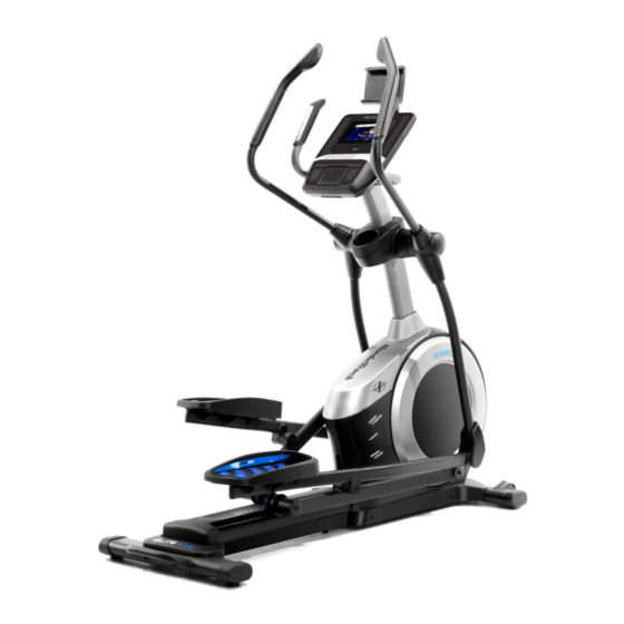
USER'S MANUAL
Model No. 23939.0
Serial No.
Write the serial number in the space
above for reference.
Serial Number
Decal
ACTIVATE YOUR
WARRANTY
To register your product and
activate your warranty today,
go to my.nordictrack.com.
CUSTOMER CARE
For service at any time, go to
nordictrackservice.com.
Or call 1-800-TO-BE-FIT
(1-800-862-3348)
Mon.–Fri. 6 a.m.–6 p.m. MT
Sat. 8 a.m.–12 p.m. MT
Please do not contact the store.
CAUTION
Read all precautions and
instructions in this manual before
using this equipment. Keep this
manual for future reference.
Advertisement
Table of Contents

Related Manuals for NordicTrack Elite 10.9i


Summary of Contents for NordicTrack Elite 10.9i
- Page 1 Serial Number Decal ACTIVATE YOUR WARRANTY To register your product and activate your warranty today, go to my.nordictrack.com. CUSTOMER CARE For service at any time, go to nordictrackservice.com. Or call 1-800-TO-BE-FIT (1-800-862-3348) Mon.–Fri. 6 a.m.–6 p.m. MT Sat.
-
Page 2: Table Of Contents
Apply the decal in the location shown. Note: The decal(s) may not be shown at actual size. NORDICTRACK and IFIT are registered trademarks of ICON Health & Fitness, Inc. The BLUETOOTH word ® mark and logos are registered trademarks of Bluetooth SIG, Inc. and are used under license. Google Maps is a trademark of Google LLC. -
Page 3: Important Precautions
IMPORTANT PRECAUTIONS WARNING: To reduce the risk of burns, fire, electric shock, or injury to persons, read all important precautions and instructions in this manual and all warnings on your elliptical before using your elliptical. ICON assumes no responsibility for personal injury or property damage sus- tained by or through the use of this product. - Page 4 18. The elliptical does not have a freewheel; the 20. Over exercising may result in serious injury pedals will continue to move until the fly- or death. If you feel faint, if you become short wheel stops. Reduce your pedaling speed in of breath, or if you experience pain while a controlled way.
- Page 5 STANDARD SERVICE PLANS...
-
Page 6: Before You Begin
BEFORE YOU BEGIN Thank you for selecting the revolutionary reading this manual, please see the front cover of this NORDICTRACK ELITE 10.9 I elliptical. The ELITE manual. To help us assist you, note the product model ® 10.9 I elliptical provides an impressive selection of fea- number and serial number before contacting us. -
Page 7: Part Identification Chart
PART IDENTIFICATION CHART Use the drawings below to identify the small parts needed for assembly. The number in parentheses below each drawing is the key number of the part, from the PART LIST near the end of this manual. The number following the key number is the quantity needed for assembly. -
Page 8: Assembly
Assembly may be easier if you have your own set • To identify small parts, see page 7. of wrenches. To avoid damaging parts, do not use power tools. 1. Go to my.nordictrack.com on your computer and register your product. • documents your ownership • activates your warranty •... -
Page 9: Of The Packing Materials (Not Shown) Under The
3. Press the Cover Mounts (106) on the underside of the Rear Stabilizer Cover (15) into the Rear Stabilizer (2). 4. With the help of a second person, place some of the packing materials (not shown) under the front of the Frame (1). Have the second per- son hold the Frame to prevent it from tipping while you complete this step. - Page 10 5. Tip: Avoid pinching the Upper Wire (110). Avoid damaging the indicated plastic tabs (A). Have a second person hold the Upright (4) Avoid pinching on the Frame (1). the Main Wire (110) and avoid Attach the Upright (4) with four M10 x 25mm damaging the Screws (99) and four M10 Split Washers (79);...
- Page 11 7. Using a plastic bag to keep your fingers clean, apply some of the included grease to the Pivot Axle (35). Insert the Pivot Axle (35) through the Upright (4) and center it. Tip: It may be helpful to use a rubber mallet.
- Page 12 9. Untie and discard the wire tie on the Main Wire (110). While a second person holds the Console (7) near the Upright (4), connect the wires on the Console to the Main Wire (110) and to the Sensor Wires (63). Insert the excess wire into the Upright (4).
- Page 13 11. Orient the Right Pedal Arm (58) as shown. Apply grease to the axle on the Right Pedal Arm (58). Attach the Right Pedal Arm (58) to the Right Roller Arm (59) with an M8 x 20mm Screw (126) and a Retainer (55); make sure that the flat side (D) of the Retainer is facing the Right Roller Arm.
- Page 14 13. Orient the Rear Upright Cover (81) as shown, and attach it to the Upright (4) with four M4 x 16mm Screws (101); start all the Screws, and then tighten them. Next, orient the Front Upright Cover (117) as shown, and press it onto the Rear Upright Cover (81).
- Page 15 15. Identify the Right Leg Inner Cover (83) and orient it as shown. Attach the Right Leg Inner Cover (83) to the Right Upper Body Leg (60) with an M4 x 16mm Screw (101) and an M5 Washer (94). Next, identify the Right Leg Outer Cover (69), orient it as shown, and press it onto the Right Leg Inner Cover (83).
- Page 16 17. Attach the Tablet Holder (127) to the Console (7) with four Tablet Holder Screws (111); start all the Tablet Holder Screws, and then tighten them. 18. Make sure that all parts are properly tightened before you use the elliptical. Extra parts may be included. Place a mat beneath the elliptical to protect the floor.
-
Page 17: How To Use The Elliptical
HOW TO USE THE ELLIPTICAL HOW TO PLUG IN THE POWER CORD A temporary adapter may 2-pole Receptacle This product must be grounded. If it should mal- be used to function or break down, grounding provides a path of connect the Adapter least resistance for electric current to reduce the risk power cord... - Page 18 HOW TO MOVE THE ELLIPTICAL HOW TO LEVEL THE ELLIPTICAL Due to the size and weight of the elliptical, moving If the elliptical rocks slightly on your floor during use, it requires two persons. Stand in front of the elliptical, turn one or both of the leveling feet (D) beneath the hold the upright (A), and place one foot against one rear of the frame or turn the leveling foot (F) under...
- Page 19 HOW TO EXERCISE ON THE ELLIPTICAL To mount the elliptical, hold the handlebars (G) or the upper body arms (H) and step onto the pedal (I) that is in the lower position. Then, step onto the other pedal. Push the pedals until they begin to move with a con- tinuous motion.
- Page 20 CONSOLE DIAGRAM FEATURES OF THE CONSOLE When you use the manual mode of the console, you can change the resistance of the pedals and the incline The advanced console offers an array of features of the ramp with the touch of a button. designed to make your workouts more effective and enjoyable.
- Page 21 HOW TO TURN ON THE POWER HOW TO USE THE TOUCH SCREEN IMPORTANT: If the elliptical has been exposed to The console features a tablet with a full-color touch cold temperatures, allow it to warm to room tem- screen. The following information will help you use the perature before you turn on the power.
- Page 22 HOW TO SET UP THE CONSOLE 5. Check for firmware updates. Before you use the elliptical for the first time, set up the First, touch the profile button, touch Settings, touch Maintenance, and then touch Update. The console. console will check for firmware updates. For more 1.
- Page 23 HOW TO USE THE MANUAL MODE 4. Follow your progress. 1. Touch the screen or press any button on the The console offers several display modes. The console to turn on the console. display mode that you select will determine which workout information is shown.
- Page 24 If there are HOW TO USE A MAP WORKOUT OR AN ONBOARD sheets of plas- WORKOUT tic on the metal contacts (B) on 1. Touch the screen or press any button on the the handgrip console to turn on the console. heart rate moni- tor, remove the See HOW TO TURN ON THE POWER on...
- Page 25 button, you can then manually control the incline When you select a workout, the screen will show an overview of the workout that includes details level (see step 3 on page 23). To return to the such as the duration and distance of the workout programmed resistance and/or incline settings of the workout, touch Follow Workout.
- Page 26 HOW TO CREATE A DRAW-YOUR-OWN-MAP If you make a mistake, touch Undo on the left side WORKOUT of the screen. 1. Touch the screen or press any button on the The screen will display the elevation and distance console to turn on the console. statistics for your workout.
- Page 27 HOW TO USE AN IFIT WORKOUT 4. Select an iFit workout that you have previously added to your schedule on iFit.com. To use an iFit workout, the console must be connected IMPORTANT: Before iFit workouts will load, you to a wireless network (see HOW TO CONNECT TO A must add them to your schedule on iFit.com WIRELESS NETWORK on page 29).
- Page 28 HOW TO CHANGE CONSOLE SETTINGS 4. Customize the unit of measurement and other settings. IMPORTANT: Some of the settings and features described may not be enabled. Occasionally, a To customize the unit of measurement, the time firmware update may cause your console to function zone, or other settings, touch Equipment Settings, slightly differently.
- Page 29 8. Exit the settings main menu. Follow the prompts on the screen to enter your password and connect to the selected wireless If you are in a settings menu, touch the back network. (To use the keyboard, see HOW TO USE button.
-
Page 30: Fcc Information
HOW TO CONNECT AN HDMI CABLE THE OPTIONAL CHEST HEART RATE MONITOR To show your console screen on a TV or monitor, plug Whether your an HDMI cable (not included) into the port on the con- goal is to sole and into a port on your TV or monitor; make sure burn fat or to that the HDMI cable is fully plugged in. -
Page 31: Maintenance And Troubleshooting
MAINTENANCE AND TROUBLESHOOTING MAINTENANCE power cord. Next, locate the small reset opening Regular maintenance is important for optimal (A) near the USB port on performance and to reduce wear. Inspect and properly the console. Using a bent tighten all parts each time the elliptical is used. paper clip, press and hold Replace any worn parts immediately. - Page 32 HOW TO ADJUST THE REED SWITCH Next, slightly loosen the indicated M4 x 16mm Screw (101), slide the Reed Switch (38) slightly closer to or If the console does not display correct feedback, away from the Magnet (43), and then retighten the the reed switch should be adjusted.
- Page 33 HOW TO ADJUST THE DRIVE BELT See EXPLODED DRAWING C on page 39. Identify the Left and Right Shields (73, 74). Remove If the pedals slip while you are pedaling, even while the M4 x 19mm Screws (5), the M4 x 25mm Screws the resistance is adjusted to the highest level, the drive (127), and the M4 x 48mm Screw (107) from the Left and Right Shields;...
-
Page 34: Exercise Guidelines
EXERCISE GUIDELINES Burning Fat—To burn fat effectively, you must exer- WARNING: cise at a low intensity level for a sustained period of Before beginning this time. During the first few minutes of exercise, your or any exercise program, consult your physi- body uses carbohydrate calories for energy. -
Page 35: Part List
PART LIST Model No. 23939.0 R0818A Key No. Qty. Description Key No. Qty. Description Frame Roller Rear Stabilizer Pedal Arm Cap Ramp Axle Cover Upright Pivot Spacer M4 x 19mm Screw Retainer Front Stabilizer Roller Arm Bushing Console Large Arm Bearing Roller Guide Right Pedal Arm Tablet Holder... - Page 36 Key No. Qty. Description Key No. Qty. Description M4 x 16mm Screw Shield Cover Cap M8 Locknut Power Cord M6 x 12mm Screw Ramp Axle M10 x 122mm Screw Small Frame Bushing Grommet Clevis Pin Cover Mount Plastic Spacer M4 x 48mm Screw M4 x 19mm Self-tapping Screw M6 x 13mm Screw Bumper...
-
Page 37: Exploded Drawing
EXPLODED DRAWING A Model No. 23939.0 R0818A... - Page 38 EXPLODED DRAWING B Model No. 23939.0 R0818A...
- Page 39 EXPLODED DRAWING C Model No. 23939.0 R0818A...
-
Page 40: Ordering Replacement Parts
ORDERING REPLACEMENT PARTS To order replacement parts, please see the front cover of this manual. To help us assist you, be prepared to provide the following information when contacting us: • the model number and serial number of the product (see the front cover of this manual) •...
Need help?
Do you have a question about the Elite 10.9i and is the answer not in the manual?
Questions and answers