Advertisement
Advertisement

Related Manuals for nvent Raychem TT-FFS Series


Summary of Contents for nvent Raychem TT-FFS Series
- Page 1 TT-FFS Fast Fuel Sensors Installation Manual...
-
Page 2: Important Safeguards
Important Safeguards The nVent RAYCHEM TraceTek Fast Fuel Sensor (FFS) must be installed correctly to ensure proper operation and detection of spilled hydrocarbons. Read these important warnings and carefully follow all of the installation instructions. • Approvals and performance are based on the use of nVent Thermal Management parts only. -
Page 3: Table Of Contents
Table of Contents General Information Pre-Installation Checks General Installation Instructions Application Specific Installation Instructions Commissioning Section Care and Maintenance nVent.com... - Page 4 nVent.com...
-
Page 5: General Information
General Information Use of the Manual This manual covers installation of the nVent RAYCHEM TraceTek Fast Fuel Sensor (FFS) for hydrocarbon fuel leak detection in commercial and industrial applications. The manual covers general area preparation and sensor installation, wiring details, testing and periodic maintenance for the FFS only. -
Page 6: Safety Guidelines
General Information For additional information contact your local nVent Dealer or Representative or contact: nVent Thermal Management Tel: +1.800.545.6258 Fax: +1.800.527.5703 thermal.info@nvent.com nVent.com Important: For warranty and agency approvals to apply, the instructions that are included in this manual and the product packages must be followed. - Page 7 Ex ia IIC T4 Ga (–40°C ≤ ta ≤ +85°C) (Ui = 15V) Ex ia IIA T4 Ga (–40°C ≤ ta ≤ +85°C) (Ui = 28V) Warranty nVent’s standard limited 24 month warranty applies to all products. A copy of the warranty can be found at nVent.com...
-
Page 8: Pre-Installation Checks
FFS Mounting Bracket for your specific application. Typical installation areas consist of a concrete floor, metal plate or container or wooden joist. Assemble the tools necessary to secure a bolt or screw into the material for your specific installation area. nVent.com... - Page 9 – 250 mm version, 1 ft, 3 ft or 10 ft lead, with or without a metal connector • nVent RAYCHEM TraceTek Probe Tester – To confirm FFS functionality before installation. • Probe Tester Operating Instructions (H58496) •...
- Page 10 Pre-Installation Checks (100 mm) (250 mm) Probe Tester FFS Installation Instructions Mounting Bracket and Cable Ties Leader Cable – TT-MLC-MC or – TT-MLC-MC-BLK nVent.com...
-
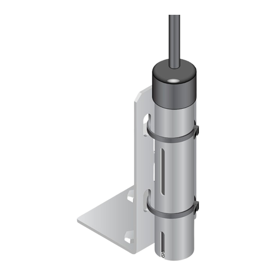
Page 11: General Installation Instructions
FFS in position. The mounting bracket includes a variety of round and oval openings which accept fasteners up to 0.250" (M6). This kit provides a simple way to mount the FFS to a variety of surfaces and structures. nVent.com... - Page 12 9.8" (250 mm) Active region 11.6" (295 mm) Note: While the FFS is water-resistant, it is not intended for applications where it is permanently immersed in water. Refer to the FFS Data Sheet (H57977) for guidance on water resistant capability. nVent.com...
- Page 13 • End termination options include a water tight connector compatible with other nVent RAYCHEM TraceTek cables or simple pig-tailed leads. The connectors have the advantage of straightforward...
- Page 14 FFS out of the way during equipment maintenance, either to protect it from damage or prevent a false alarm due to fuel spilled during maintenance activities. Therefore, the retention method used should allow easy removal and re-installation. nVent.com...
-
Page 15: Application Specific Installation Instructions
FFS should be mounted in the recessed area. – Find the ideal mounting location by spilling water at different spots within the recessed area to determine the point to which most spilled fluid will flow to. – Mount the FFS in this spot. nVent.com... - Page 16 – Find the ideal mounting location by spilling water at different spots within the weir to determine the point to which any spilled fluid will flow. – Mount the FFS in this spot. nVent.com...
- Page 17 – Secure to the floor using appropriate bolts, screws or glues. – Seal the corners and floor interfaces to prevent fuel leakage out of the weir. • The FFS should then be mounted within the weir. nVent.com...
- Page 18 FFS is centered in the desired fuel detection zone of the sump or drain. The 250 mm version of the FFS is recommended for these installations as it provides a longer sensor and can accommodate larger variations in water level. nVent.com...
- Page 19 It is recommended that the placement be against the tank side of the containment ring in order to protect it from damage. Installation of the FFS should be flush with the bottom of the containment ring surface. nVent.com...
- Page 20 • The mounting bracket may be used with an appropriate connection method to ensure the roof integrity is not compromised. • Sufficient jumper or leader cable must be used to allow full range of roof motion without creating any tension on the FFS connector or connection cable(s). nVent.com...
- Page 21 Using the cover will prolong the life of the FFS when used in outdoor environments. D I E nVent.com...
- Page 22 This cover comes in two versions, one for each size of the FFS. • TT-FFS-EEC-100, Part Number: P000001142 • TT-FFS-EEC-250, Part Number: P000001143 Detailed installation instructions for assembling the Extreme Environmental Cover (EEC) onto the FFS are provided in the EEC Installation Instructions (H58519). nVent.com...
-
Page 23: Commissioning Section
Commissioning Section Once installed, both the FFS and the nVent RAYCHEM TraceTek Leak Detection System should be tested to confirm an alarm will be generated at the point of user interface. The user interface could be the Sensor Interface Module (TTSIM), TTC-1, a nVent RAYCHEM... - Page 24 5.1.1 Functional Testing – FFS In System Where possible, functional testing of the FFS with it connected in the full nVent RAYCHEM TraceTek system is preferred as this will validate functionality of the system in addition to that of the FFS.
- Page 25 5) If applicable, check the alarm output from the third party system to confirm that an alarm has been generated by the FFS. a. Refer to the third party system information to determine the appropriate leak alarm response. nVent.com...
- Page 26 Care and Cleaning instructions (H58307) to ensure no contamination is preventing the test fluid from contacting the sensor board, and retest. Or contact your local nVent representative. 7) Once the leak detection alarm has been confirmed, reset the FFS. If a light...
- Page 27 Commissioning Section a. If applicable, verify that no alarms exist at the Sensor Interface Module (TTSIM), TTC-1 or other nVent RAYCHEM TraceTek controller. b. If applicable, verify that no alarms exist at the master controller (TS12 or TTDM-128). c. If applicable, verify that any third party systems are not indicating an alarm.
- Page 28 Refer to the Sensor Interface Module or Master Control system manuals or contact your local nVent representative for assistance. 8) Once the leak detection alarm has been confirmed, the Mapping Cap may be replaced with the functionally tested FFS.
- Page 29 Apply additional hydrocarbon if necessary. c. If there is no response, contact your local nVent representative for assistance. 6) Once the leak detection alarm has been confirmed, clean the FFS using the procedure specified in the FFS Care and Cleaning Instructions (H58307).
-
Page 30: Care And Maintenance
Check with your facility regulations to ensure the testing recommended below is within the local guidelines. If they are not, then functional testing must be done in an approved location. nVent.com... - Page 31 Tester, use the following procedure: 1) Remove the FFS from its mounting bracket and unscrew the metal connector. It will be necessary to remove the shrink tube seal which should have been applied over the connectors. Transport the FFS to the test area. nVent.com...
- Page 32 7) Confirm that the FFS has reset and is ready for use by connecting it to the Probe Tester and verifying that the LEDs do not flash until the Red Button has been pushed. 8) The unit may now be returned to service. nVent.com...
- Page 36 © 2018 nVent. All nVent marks and logos are owned or licensed by nVent Services GmbH or its affiliates. All other trademarks are the property of their respective owners. nVent reserves the right to change specifications without notice.
Need help?
Do you have a question about the Raychem TT-FFS Series and is the answer not in the manual?
Questions and answers