Table of Contents
Advertisement
OPERATORS
MANUAL
IBEX
1000 Series
®
Climb Assist System
(Models 1050, 1065, 1080, & 1100)
WARNING:
The IBEX
1000 Climb Assist System is NOT a safety device and must only be used when
®
user is connected to independent fall arrest system.
All personnel operating this equipment must read and completely understand this manual.
All personnel must be thoroughly trained in the use of the equipment and its operational and
safety features.
Only authorized and physically fit personnel shall operate the equipment.
All persons operating this equipment must wear a safety harness at all times and tie-off as
required.
Any operation in violation of these instructions is at the operator's own risk and may result
in serious injury.
Only use spare parts supplied by Power Climber Wind.
Advertisement
Table of Contents

Summary of Contents for Power Climber Wind IBEX 1000 series
- Page 1 All persons operating this equipment must wear a safety harness at all times and tie-off as required. Any operation in violation of these instructions is at the operator’s own risk and may result in serious injury. Only use spare parts supplied by Power Climber Wind.
- Page 2 Manufacturer Power Climber Wind A Division of SafeWorks, LLC 365 Upland Drive Seattle, WA 98188 Customer Support (Americas) Tel: +1 (877) PCWIND1 (729-4631) or outside the U.S.: +1 (206) 394-5306 Fax: +1 (206) 575-6240 Email: CustomerService@PowerClimberWind.com www.PowerClimberWind.com Customer Support (Europe/Asia Pacific) Tel: +32 3 451 05 00 Email: Wind@PowerClimber.be...
-
Page 3: Table Of Contents
Table of Contents 1. SYMBOLS USED IN THIS MANUAL ............4 2. EQUIPMENT DESCRIPTION..............5 2.1. General Description ................5 2.3. Approvals ....................5 2.2. Specifications ..................5 2.4. General View..................6 3. ASSEMBLY AND INSTALLATION INSTRUCTIONS ......7 3.1. Standard Components ................7 3.2. Bottom Assembly ..................8 3.3. -
Page 4: Symbols Used In This Manual
1. SYMBOLS USED IN THIS MANUAL STOP Stop action and follow the instructions before continuing. Warns against possible immediate serious injury WARNING or death. Warns against possible injury. CAUTION Warns against possible electrical shock hazard. ELECTRICAL HAZARD Must read this before performing any action that NOTE follows. -
Page 5: Equipment Description
FCC Warning: Changes or modifications not dance with the instructions, may cause harmful expressly approved by Power Climber Wind for interference to radio communications. Operation is compliance could void the user’s authority to oper- subject to the following two conditions: ate the equipment. -
Page 6: General View
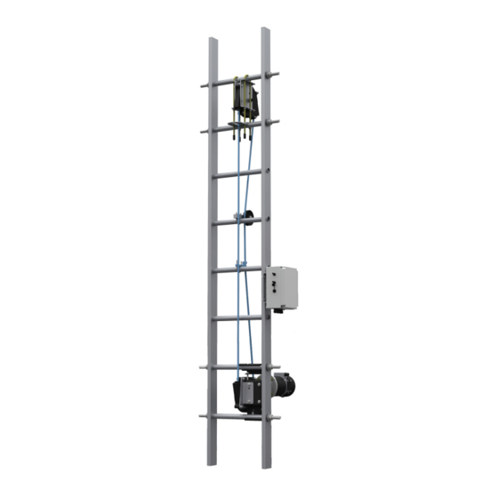
2.4. General View Upper rung Top sheave assembly reinforcements Round reinforced polymer belt Guide roller Electrical control box Gear motor Lower rung reinforcements Motor mounting brackets Drive sheave assembly Page 6 of 24 Reference: 702991-1 Issue date: 26-Jan-2012 Revision: E... -
Page 7: Assembly And Installation Instructions
3. ASSEMBLY AND INSTALLATION INSTRUCTIONS NOTE: These installation instruc- 3.1. Standard Components tions are only a guide. Each tower The IBEX 1000 climb assist system consists of ® can present unique complications the following parts: that must be addressed on an individual basis. -
Page 8: Bottom Assembly
Fasteners: The components of the IBEX 1000 are as- ® NOTE: Either a lock washer, star sembled using standard fasteners. washer or Nylok nut shall be used for all fasteners All bolts should be firmly tightened. If nylon lock nut is used, bolt thread shall protrude passed the nylon lock nut by at least one thread. -
Page 9: Upper Assembly
3.3. Upper Assembly NOTE: Tools Required: 17mm combination wrench and Two (2) 1. Unpack the following and place in the Lift Bag: 29mm Wrenches, Lift Bag capable of Item Description holding all tools and components. Upper Sheave Assembly 10mm U-Bolt Stop Plate Pull-In Roller Rung Reinforcements... -
Page 10: Belt Path Solutions
5. Install the Pull-In Roller one rung above deck level. Install the Pull-In Roller on top of the rung and align with the upper sheave assembly. Install the Rung U-Bolt with threads up and fasten with included Nylon Locknuts. Tighten with 11mm Combination Wrench until slight rung deformation has occurred. -
Page 11: Push-Out Belt Rollers
3.4.2. Push-Out Belt Rollers For towers with obstructions near the ladder opposite the climber (i.e. flip-down ladder rest sta- tions), Push-Out Belt Rollers can be used to extend the clearance between the belt and the ladder. Installation of Push-Out Belt Rollers is identical to the Pull-In Belt Guides (Section 3.4.1.). -
Page 12: Belt Welding
3.5. Belt Welding Refer to belt tensioning, welding, and qualification procedures. Only persons trained and qualified by PowerClimber Wind shall complete belt installa- tion. 3.6. Electrical Components NOTE: Tools Required: 13mm Combination Wrench, 6mm Hex 3.6.1. Control Box Wrench, 11mm Combination Wrench, 7mm Nut Driver, Flathead 1. - Page 13 2. Mount the Electrical Control Box to the ladder and tighten the Pipe Clamps using the Flathead Screwdriver. 3. Remove the Motor Electrical Cap from the Mo- tor with a Flathead Screwdriver. 4. Open the Cable Gland and feed the power wires with the ring terminals through the gland.
-
Page 14: Easyclimb Controller
3.6.2. EasyClimb Controller 14. Press UP (twice if needed): Verify that the belt moves up at a speed that varies inversely with the load applied to the EasyClimb Controller. 15. While load is applied and the belt is running, press STOP: Verify that the belt stops and does not respond to load. -
Page 15: Operation Instructions
4. OPERATION INSTRUCTIONS WARNING: The IBEX 1000 climb ® assist system is not a safety device and 4.1. Use of the EasyClimb Controller must only be used in conjunction with an independent personal fall arrest 4.1.1. To Set Level of Assistance system. -
Page 16: To Descend
4.1.3. To Descend NOTE: 1. Connect the EasyClimb Controller between the • If the load in the EasyClimb Con- harness chest ring and the rope grab clipped to the troller does not reach 9.07 klg. (20 belt. lbs) within 15 seconds, the motor will 2. -
Page 17: Maintenance Instructions
5. MAINTENANCE INSTRUCTIONS The IBEX 1000 requires minimal maintenance. ® All bearings are sealed and do not require lubrica- tion 5.1. Periodic Inspection 5.1.1. Belt Inspection As a moving part, the round assist belt is subject to wear with use. Visual inspection of the belt for abrasion or other damage or weld separation should be performed regularly. -
Page 18: Replacement Of Damaged Components
Wind by factory return. During the warranty period a replacement controller or control box will be supplied if required. WARNING: Only use parts supplied by Power Climber Wind. Use of non-authorized parts will void the warranty. NOTE: See the spare parts list in sec- tion 5.5 for replacement items. -
Page 19: Electrical Schematics And Wiring Diagrams
220 Vac 5.5. Customer Service For service requests or spare parts orders, contact Power Climber Wind Customer Service in the U.S. or Canada at CustomerService@PowerClimberWind.com or via telephone inside the U.S. at +1 (877) PC- WIND1 or outside the U.S. at +1 (206) 394-5306. In Europe/Asia Pacific call +32 3 451 05 00 or e-mail Wind@PowerClimber.be... - Page 20 2012 Power Climber Wind A division of SafeWorks, LLC 702991-1 Rev. E...
Need help?
Do you have a question about the IBEX 1000 series and is the answer not in the manual?
Questions and answers