Table of Contents
Advertisement
Quick Links
Advertisement
Table of Contents

Related Manuals for DOMUSA TEKNIK BIOCLASS HC


Summary of Contents for DOMUSA TEKNIK BIOCLASS HC
- Page 1 INSTALLATION AND OPERATING INSTRUCTIONS BIOCLASS HC CGM-04/392 ER-0170/1996...
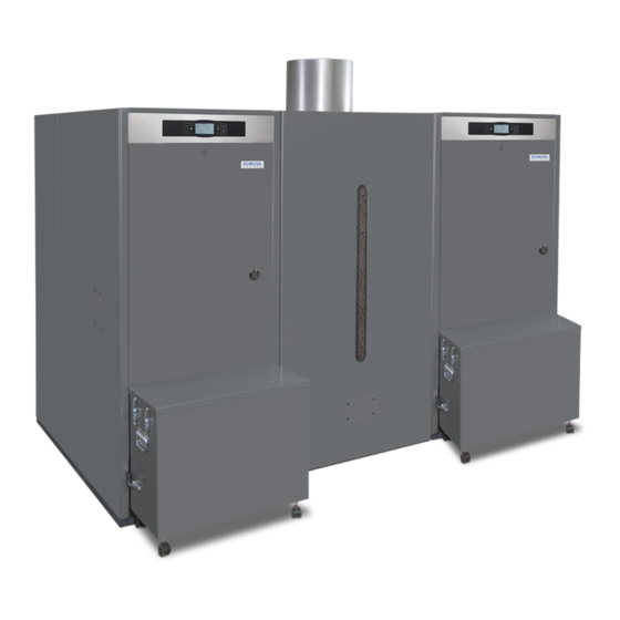
- Page 2 Thank you for choosing a DOMUSA TEKNIK heating boiler. Within the product range offered by DOMUSA TEKNIK you have chosen BioClass HC model. This is a set of two boilers capable of providing the ideal comfort level for your heating and / or domestic hot water, always accompanied by a proper hydraulic system and fueled by wood pellets.
-
Page 3: Table Of Contents
ÍNDICE Pág. 1 GENERAL DESCRIPTION ..............................3 2 LIST OF COMPONENTS ..............................4 3 CONTROL COMPONENTS............................. 5 4 INSTALLATION INSTRUCTIONS ..........................6 4.1 L ......................................6 OCATION 4.2 H .................................. 7 YDRAULIC INSTALLATION 4.3 C ..........................7 ASCADE CIRCUIT CONTROL AND REGULATION 4.4 I .................................. - Page 4 BioClass HC 13.3 M (P.19)........................... 33 INIMUM BOILER WATER PRESSURE 13.4 M (P.27) ..................33 AXIMUM HEATING FLOW TEMPERATURE OF MIXED CIRCUITS 14 ADDITIONAL FUNCTIONS ............................34 14.1 T ......................... 34 IME OF THE AUTOMATIC PELLET FEEDING CYCLE 14.2 R (P.24) ..............................
-
Page 5: General Description
Easy to introduce boilers in the boiler room and reduction in space occupied because they share the pellet reserve tank and the fuel suction system. In the BioClass HC configuration, the two boilers are fed from the same reserve tank. In addition, this reserve tank is fitted with a fuel suction system. -
Page 6: List Of Components
BioClass HC 2 LIST OF COMPONENTS 1 2 3 BIOCLASS HM 25 / 43 BIOCLASS HM 66 1. Feed auger. 8. Fuel entrance safety thermostat 2. Sensor housing. 9. Boiler body 3. Automatic Air vent. 10. Ash drawer 4. Flue gas outlet 11. -
Page 7: Control Components
3 CONTROL COMPONENTS 17 18 14. MENU touch button: 17. ON touch button: This button is used to access and browse This button switches on and off the boiler. through the "User Menu". 18. Boiler temperature select touch button: 15. Digital display: This button is used to select the boiler set point It is the main boiler functioning display, on temperature. -
Page 8: Installation Instructions
Contact your supplier. Keep the packaging elements out of reach of children, as they can be dangerous. Be aware that the base of the boiler BioClass HC is fixed to the wooden pallet with four screws. When you no longer wish to use the boiler, disable the parts that could be a potential source of hazard. -
Page 9: Hydraulic Installation
). The J6 borne is equipped with a jumper which is removed to connect (see the controller. The following figures show an example of a hydraulic layout for a BioClass HC boiler system with an inertia tank or hydraulic separator regulated by an E26 controller (optionally supplied by DOMUSA TEKNIK ). - Page 10 BioClass HC 4.3.1 Example of an installation with a buffer tank BioClass HC 66/66 BioClass HC 25/66 or BioClass HC 43/66 Vs: Security valve. Kfs: Boiler sensor Vee: DHW expansin vessel. Ss: DHW sensor. Vfas: Flow sensor. Bt: Buffer tank.
- Page 11 4.3.2 Example of installation with hydraulic separator BioClass HC 66/66 BioClass HC 25/66 or BioClass HC 43/66 Kfs: Boiler sensor Vs: Security valve. Ss: DHW sensor. Vee: DHW expansin vessel. Bt: Buffer tank. Vfas: Flow sensor. Ac: DHW tank VR: Equilibrating valve Vr: Non-return valve.
-
Page 12: Installing The Hopper
BioClass HC 4.4 Installing the hopper DOMUSA TEKNIK supplies a reserve tank with the boilers, with an fuel suction system for the transport and storage of pellets. Given that the tank is reversible, there is the choice to locate the boiler on the left or on the right. -
Page 13: Electrical Connection
4.6 Fuel BioClass HC boiler must be fuelled by EN Plus-A1 or DIN PLUS certified wood pellet. The DIN PLUS or EN Plus-A1 certificate assures that the fuel’s humidity levels and calorific value are ideal for optimum boiler functioning. -
Page 14: Combustion Product Removal
4.7 Combustion product removal The BioClass HC boiler is an assembly of two BioClass HM boilers and it is essential that each boiler is connected to a flue, i.e. a smoke duct able to create a pressure drop (which in this case should be between 0.10 and 0.20 mbar), in compliance with the applicable laws to this regard. -
Page 15: Commissioning Of The Boiler
IMPORTANT: Switching on the boiler with no water inside could result in serious damage. 5.4 Initial calibration of the feed auger BioClass HC boiler is equipped with a feed auger to supply the fuel. Follow the instructions "Installing the hopper”... -
Page 16: Commissioning
In order for the guarantee to be valid , the boiler must be commissioned by personnel authorised by DOMUSA TEKNIK . Before beginning the commissioning, the following must be complied with: - The boiler must be plugged in to the mains. -
Page 17: Digital Display
6 DIGITAL DISPLAY BioClass HM boiler is equipped with a digital touch display for viewing and adjustment of the different boiler settings. The display has various display areas where different icons and numbers appear to indicate the different status of the boiler. Boiler status: Heating function enabled. - Page 18 BioClass HC Technical icon: It is displayed when any of the boiler's technical parameter on the "Technical Menu" "Setup menu" is displaying or modifying. Auxiliary icons. Value or setting related to a temperature is shown by the numerical digits. bar Value or setting related to the boiler water pressure is shown by the numerical digits.
-
Page 19: Operation
7 OPERATION BioClass HC boiler is an assembly of two BioClass HM heating boilers. For a correct running, it has to be connected to a cascade regulation controller. 7.1 Boiler operation The activation of the BioClass HM boilers is managed by the controller connected in the ( TA1 ) strip of each boiler. -
Page 20: User Menu
BioClass HC 8 USER MENU User Menu " " shows the settings related to boiler functioning on the digital display. To access this menu press MENU; press this button repeatedly to browse through the different settings available. When one of the options is displayed, after 20 seconds the display returns to main "User Menu"... -
Page 21: Ashtray Status
8.1 Ashtray status "Setup menu") When "Ashtray Empty Warning" function is activated (see , the boiler warns about "Ashtray status" the ashtray is full and must be emptied. The parameter allows checking the fill level and the screen shows the ash scale bar which indicates the fill level of the ashtray. When it is full, an "Empty the ashtray"... -
Page 22: Setup Menu
BioClass HC 9 SETUP MENU "Setup menu" consists of operating parameters of the boiler which can be adjusted by the user (Ashtray empty warning, timer programming, time setting, ...) “Setup menu" To access to the . Browse through the menu by pressing the symbols " + " or " -... -
Page 23: Timers Programming Process
9.1 Timers programming process BioClass HM boiler allows setting 2 different timers: boiler timer and fuel suction system timer. The default setting for the timers is disabled (" - - - - "), so the functioning that is regulated by each timer will operate 24 hours. -
Page 24: Time Setting
BioClass HC 9.4 Time setting “Time setting” “Setup menu” When parameter of is displayed, press to access. The first two digits of numerical digits blinks (hours) and setting process begins: (19) Set the hour value by pressing “ + " or " - " of DHW . -
Page 25: Empty Ash Box Notice
9.5 Empty ash box notice With this function activated, the boiler lets us know when the boiler ash box is full, so that we “Ashtray status” “User Menu” proceed with its emptying. The parameter allows checking the "Empty the ashtray" actual fill level. -
Page 26: Calibration Menu
BioClass HC 10 CALIBRATION MENU "Calibration Menu" consists of a number of processes and parameters that allow the correct set up of the boiler. “Calibration Menu" To access the , the boiler must be switched off by pressing tactile button. After having switched off the boiler press for 5 seconds to access to the menu. -
Page 27: Feed Auger Filling
10.1 Feed auger filling During the commissioning of the boiler, before calibrating the feed auger or if the hopper runs out of fuel, it is compulsory to fill of fuel the feed auger. By means of this parameter the feed auger will be filled of fuel, process required for a correct boiler functioning. -
Page 28: Feed Auger Calibration
BioClass HC 10.2 Feed auger calibration By means of calibrating the feed auger the electronic controller of the boiler adjusts the optimum amount of fuel required to supply the burner and to produce the correct heat output and combustion. By means of this parameter the feed auger calibration procedure will be made, process required for a correct boiler functioning. -
Page 29: Manual Setting Of Feed Auger Calibration
10.3 Manual setting of feed auger calibration By means of this parameter the weight obtained in the feed auger “Manual setting of calibration procedure can be set manually. When feed auger calibration” "Calibration parameter is displayed ( ) on Menu" to access and set the value desired by pressing "... -
Page 30: Technical Menu
BioClass HC 11 TECHNICAL MENU Technical Menu " " consists of a number of technical operating parameters that only have to be modified by a person with sufficient technical knowledge of the meaning of each parameter. Any “Technical Menu” inappropriate setting of a parameter of can cause a serious malfunctioning of the boiler and could cause damages to people, animals or things. - Page 31 Nº Parameter Display Fuel type P.07 (Not available for BioClass HC) P.13 Boiler minimum temperature mode P.14 Minimum boiler temperature (ºC) P.15 Heating pump post-circulation time (min) P.18 Boiler's pump operating mode (BC) P.19 Minimum boiler water pressure (bar) P.20...
-
Page 32: Entry And Set The Access Code ("Cod
Parameter Display Auxiliary parameter for fuel selection P.26 (Not available for BioClass HC) 11.1 Entry and set the access code ("cod", P.25) When the access code request is displayed or to set a new one ( P.25 ), press to access. SET symbol blinks and it would be possible to enter the code or set it. -
Page 33: Boiler's Setup Parameters
12 BOILER'S SETUP PARAMETERS The following parameters in the " Technical Menu " allow to adjust the boiler to each installation. They only may be modified by a person with sufficient technical knowledge of the meaning of each parameter. Any inappropriate setting of a parameter of “Technical Menu”... -
Page 34: Boiler Minimum Temperature Mode
BioClass HC 12.8 Boiler minimum température mode (P.13, P.14) By means of parameters P.13 and P.14 a different mode of temperature managing may be set (by default P.13 = 2 ), if heating or/and DHW services are enabled. When parameter P.13 is set to 0, by parameter P.14 the minimum temperature can be selected as desired, between 30 and 60 ºC. -
Page 35: Heating Circuit's Setup Parameters
13 HEATING CIRCUIT'S SETUP PARAMETERS BioClass HM is equipped with an electronic controller to manage efficiently the automatic functioning of the boiler. It also has the following additional parameters to regulate the heating circuit connected. They only may be modified by a person with sufficient technical knowledge of the meaning of each “Technical Menu”... -
Page 36: Additional Functions
BioClass HC 14 ADDITIONAL FUNCTIONS BioClass HM boiler includes the following additional control functions. They only may be modified by a person with sufficient technical knowledge of the meaning of each parameter. Any inappropriate “Technical Menu” setting of a parameter of can cause a serious malfunctioning of the boiler and could cause damages to people, animals or things. -
Page 37: Multi-Functional Relay
15 MULTI-FUNCTIONAL RELAY (P.20) BioClass HC is equipped with an auxiliary relay output that may be used to select a series of additional functions that increase the boiler performance, features and comfort of the installation. Several operating modes may be set at P.20 parameter of the “Technical Menu”... -
Page 38: Safety Lock-Outs
BioClass HC 16 SAFETY LOCK-OUTS The boiler’s electronic controller may activate the following safety lock-outs to stop the boiler functioning in order to prevent serious damages. When any of these lock-outs occur, the boiler will switch off and an alarm code will be displayed on boiler's screen. -
Page 39: Low Pressure Lock-Out
16.3 Low pressure lock-out When this lock-out occurs, “E19” alarm code will appear on the digital display. The burner and the boiler's circulation pumps will switch off, cutting off the heating and water flow to the installation. This lock-out occurs when the pressure of boiler's water drops below the value set at P.19 "Technical menu"... -
Page 40: Boiler Maintenance
Various maintenance operations should be carried out at different intervals of time to keep the boiler in perfect working order. The yearly maintenance operations should be carried out by personnel authorised by DOMUSA TEKNIK . 19.1 Frequency of maintenance of the boiler and chimney The most important aspects to be checked are as follows: Nº... -
Page 41: Burner Cleaning Procedure
19.2 Burner cleaning procedure The following procedure is recommended for a correct cleaning of the burner: BioClass HM 66... - Page 42 BioClass HC BioClass HM 25 y 43 P U S H...
-
Page 43: Heat Exchanger Cleaning Procedure
19.3 Heat exchanger cleaning procedure The following procedure is recommended for correctly cleaning the heat exchanger: BioClass HM 66... - Page 44 BioClass HC BioClass HM 25 and 43...
-
Page 45: Draining The Condensate Water
19.4 Draining the condensate water The draining device to take out the condensate water from the chimney should not be altered in any way and it must be kept free of obstructions. 19.5 Boiler water characteristics In areas with water hardness of over 25-30 ºfH, treated water must be used in the heating installation to avoid any scale deposits on the boiler. -
Page 46: Diagrams And Measurements
BioClass HC 20 DIAGRAMS AND MEASUREMENTS BioClass HC 66/66 2140 IC: Heating flow 1 ¼” F RC: Heating return 1 ¼” F SH: Fume outlet. V: Drainage cock. VS: Pressure relief valve, 1/2" F... - Page 47 BioClass HC 43/66 and 25/66 2140 1360 IC IC Dimensions (mm) IC: Heating flow 1 ¼” F RC: Heating return 1 ¼” F 25 / 66 SH: Fume outlet. 43 / 66 V: Drainage cock. VS: Pressure relief valve, 1/2" F...
-
Page 48: Connections Diagram
BioClass HC 21 CONNECTIONS DIAGRAM 21.1 Boiler 14 13 N 12 11 10 9 Fuel suction system power supply cable Fuel suction system communication cable Brown Blue 23 22 21 20 19 18 17 16 15 Lago FB OT+ Rbt/Ra: Resistance. -
Page 49: Burner
21.2 Burner Qout: Burner outputs connector. R: Ignition heater. LC: Burner ash cleaning device . : Closed switch . : Open switch . Qin: Burner inputs connector. FCq: Burner switch . FR: Photocell . FCp: Ash cleaning device switch . -
Page 50: Electrical Diagram
BioClass HC 22 ELECTRICAL DIAGRAM Display board S1 S2 Power supply board TS: Safety thermostat. Qout: Burner outputs connector. TE: Fuel entrance safety thermostat. Qin: Burner inputs connector. Cv: Fan capacitor. LCD: Display communication connector. SPW: Water pressure sensor. J4: Communication connector. -
Page 51: Technical Data
23 TECHNICAL DATA BioClass HM BioClass HM BioClass HM MODELO Nominal heat output 25,3 42,7 64,8 Efficiency at maximum heat output 92,1 Minimum heat output 11,4 18,0 Efficiency at minimum heat output 94,5 94,8 CO at maximum heat output (10% O mg/m OGC (organic gaseous substances) at <5... -
Page 52: Hydromotive Pressure And Pressure Drop
The BioClass HM 66 boiler must be installed together with a Anti-condensation Kit, optionally supplied by DOMUSA TEKNIK . The kit primarily comprises a high efficiency circulation pump and a thermostatic mixing valve to ensure a minimum return temperature of 50ºC. - Page 53 For the appropriate sizing of the hydraulic installation, as well as the pump operation curves, the pressure loss caused by the boiler BioClass HM 66 and the thermostatic mixing valve should be taken into account. The following graph shows the pressure loss curves for the boiler and for the boiler with the thermostatic valve (anti-condensation):...
-
Page 54: Spare Parts List
BioClass HC 25 SPARE PARTS LIST 25/43 boiler 19 20... - Page 55 Nº. Code Description Nº. Code Description CVAL000034 Drain valve RELEBIO010 Electrical board 25 GFOV000002 Automatic air vent RELEBIO012 Electrical board 43 SEPO001452 Engine cover SEPO002196 Air pressure sensor protection SCHA009633 Tapa registro de humos CELC000331 Air pressure sensor CVAL000017 Safety valve SEPO002195 Air pressure sensor support SEPO001925...
- Page 56 BioClass HC 66 boiler 6 5 4 Nº. Code Description Nº. Code Description SEPO002111 Ash drawer SEPO002098 Rear panel SEPO001451 Flange cover SEPO001799 Stiffness SEPO001497 Transportation handle CFER000261 Spring SEPO002288 Air pressure sensor support SEPO002340 Top Cover CELC000331 Air pressure sensor...
- Page 57 66 boiler Nº. Code Description RQUEBIO029 Burner SCON001127 Compressor drawer CFOL000002 Spy hole nut COTR000010 Spy hole glass RBIO000045 Internal supply line CELC000252 Pressure transducer RBO000022 Heat exchanger CFOV000024 Automatic air vent CVAL000017 Safety valve SCON001081 Manifold box CVAL000034 Drain valve SCON000908 SCON001132 Fan lead...
- Page 58 BioClass HC 25/43 burner...
- Page 59 Nº. Code Description Nº. Code Description SCON000935 Burner body25 SCON001084 Burner body43 CQUE000177 Lever MAIS000162 Top insulation 25 CFUR000032 Burner cleaner 25 CFUR000033 Burner cleaner 43 MAIS000163 Top insulation 43 SEPO002175 Connectors support RCON000008 Rack sub-unit 25 RCON000009 Rack sub-unit 43 CTOR000100 Screw for plastic 4,1x16 CQUE000042...
- Page 60 BioClass HC 66 burner 56 57 58 41 40 39 14 13 11 10 54 10...
- Page 61 Nº. Code Description Nº. Code Description CFER000152 Burner structure CELC000352 DIN-912 M6x14 screw SEPO002103 Cover of burner structure CTOR000265 Rear burner cover CTOE000345 DIN-933 M6x25 screw SCON001304 Flap CTOR000146 DIN-125-A2 M6 washer SCON001305 DIN-933 M4x8 screw CTOR000084 696 2Z bearing CTOR000281 Right side insulation CFER000129...
- Page 62 BioClass HC 25/43 heat exchanger camshaft system 18 17 Nº. Code Description Nº. Code Description CTOE000242 Deflector coil CTOE000172 Cam system washer CFER000284 Blade pin CFER000129 Bearing CTOR000162 Flat washer CTOR000230 DIN-985 M6 self-locking nut SCON000752 Deflector tube support 25...
- Page 63 66 heat exchanger camshaft system Nº. Code Description Nº. Code Description CTOE000330 Deflector coil CTOR000132 DIN-9021 M4 washer SCON000756 Deflector tube CFER000292 DIN-7343 6x30 elastic pin SCON000779 Cleaning plate CFER000129 Bearing SCHA011071 Plate fastener CTOR000280 DIN-985 M3 self-locking nut SCON000306 Outer plate SCON000925 Deflector tube support...
- Page 64 BioClass HC Electrical board Nº. Code Description Nº. Code Description RBIO000032 Electrical board CFER000126 Bracket SEPO001303 Panel fastening SEPO001787 Drawer cover CELC000234 Boiler sensor SEPO002223 Drawer REBI335XXX Supply electronic card CELC000036 Automatic closure SCHA009150 Ground plate SEPO002333 Cover CFOV000151 Capacitor...
- Page 65 Feed auger Nº. Code Description CFOV000136 25W motor transmission 1/180 CFOV000142 YN 80 capacitor SEPO001637 Fixing plate SCON000863 Feed Screw 25/43 SCON000579 Feed Screw 66 SEPO002125 Feed tube 25/43 SEPO001612 Feed tube 66 CFER000019 Clamp STUR000004 Polyurethane flex hose 25 STUR000005 Polyurethane flex hose 43 STUR000028...
- Page 66 BioClass HC Mangueras de conexiones eléctricas Nº. Code Description CELC000343 Communication Cable CELC000353 Thermostat cable CMAZ000123 Wiring harness CELC000344 Burner output cable CELC000349 Water pressure sensor cable CELC000348 Burner input cable CELC000345 Air pressure sensor cable CMAZ00141 Power supply link wiring...
-
Page 67: Alarm Codes
26 ALARM CODES BioClass HC boiler is equipped with an electronic controller that performs continuous self-testing to detect any boiler malfunctioning. When it detects a functioning error, this is indicated by an alarm code on the display. The table below shows the list of the alarm codes:... - Page 68 BioClass HC CODE ALARM DESCRIPTION The pressure of water in the installation drops below the Technical minimum pressure set at P.19 parameter of the·” Menu ” (by default 0,5 bar). The boiler will lock out. To unlock it, fill the installation again up to 1 - 1.5 bar.
- Page 69 Communication error with BIO Hydraulic Kit Hydraulic Kit. E-37 not valid for BioClass HC If this alarm occurs repeatedly contact the nearest official technical assistance service. Check the air pressure sensor and that the burner and ashtray Lasting insufficient air depression during are correctly fitted to the boiler.
-
Page 70: Guarantee Conditions
4. The commercial guarantee will be null and void in the following cases: - If the annual overhaul by personnel authorised by DOMUSA TEKNIK has not been carried out. - If the boiler has not been installed in accordance with the applicable laws and regulations for this type of appliance. - Page 71 NOTES: ............................................................................................................................................................................................................................................................................................................................................................................................................................................................................................................................................................................................................................................................................................................................................................................................................................................................................................................................................................................................................................................................................................................................................................................
- Page 72 Bº San Esteban s/n Ellesmere Port, CH65 9BF 20737 ERREZIL (Gipuzkoa) Tel: 0151 909 6222 Tel: (+34) 943 813 899 www.domusateknik.com DOMUSA TEKNIK reserves the right to make modifications of any kind to its product *CDOC001566* characteristics without prior notice. CDOC001566 02/18...
Need help?
Do you have a question about the BIOCLASS HC and is the answer not in the manual?
Questions and answers