
Summary of Contents for Intelligent Lighting Controls, Inc. LightLEEDer
- Page 1 INTELLIGENT LIGHTING CONTROLS, INC. Energy Saving Lighting Controls Operation Manual Includes product details, installation and programming information for LightLEEDer lighting control systems. www.ilc-usa.com...
- Page 2 O P E R A T I O N M A N U A L Includes product details, installation and programming information for LightLEEDer lighting control systems. Version 1C 3/14/17 Class A FCC Device Statement Warning: Changes or modifications to this unit not expressly approved by the party responsible for compliance could void the user’s authority...
- Page 3 Introduction Thank you for purchasing the IlC lightleeDer lighting control system. The lightleeDer line is a very exible and quality product to meet all of your lighting control needs. These panels are microprocessor- based programmable lighting controllers with networking capabilities. You can program each of the controller’s inputs or data line devices to control any or all of the relay outputs.
-
Page 4: Table Of Contents
1.5 Keypad and Display Module ..................1-10 1.6 Reliant40 lighting Control Relays ................1-10 1.7 Optional Modules ......................1-10 1.8 lightleeDer network ....................1-10 Section 2 Installation 2.0 Pre-Installation Check list ..................2.1 Mounting the Controller ..................... 2.1.1 location ......................... - Page 5 3.7.2 Configure Timers....................3.7.3 Timer Mapping Control ..................3.7.4 OFF hour sweeps ....................3.7.5 Program Open and Close Times..............3.7.6 Blink Alerts and Alarms ..................3.7.7 Configure Timed-On..................3.7.8 Test Programmed Timers ................. ILC LightLEEDer Operation Manual Version 1C 3/14/17...
- Page 6 Appendix J: lightsync Input Board and Photocell Controller ...... Appendix K: lightsync hub and Occupancy sensor ........Appendix l: networked Room Controllers and expansion Panels ..... Appendix M: lightleeDer emergency Ul 924 lighting Control ....ILC LightLEEDer Operation Manual Version 1C 3/14/17...
-
Page 7: Section 1: Lighting Controller Details
Section 1 Lighting Controller Details Intelligent Lighting Controls, Inc. ILC LightLEEDer Operation Manual Version 1C 3/14/17... - Page 8 1.1 Transformer ........................1.2 Controller Board ......................1.3 Output Board ........................1.4 Input Module ........................1.5 Keypad and Display Module ..................1.6 Reliant40 lighting Control Relays ................1.7 Optional Modules ......................1.8 lightleeDer network ....................ILC LightLEEDer Operation Manual Version 1C 3/14/17...
- Page 9 4 COM POWER EXT +V 77013488A 24VAC CT EXTCOM 97013488 Input Board 77013485A Switch Inputs and Pilot 24VAC CT Outputs Output Board POWER 77013488A 24VAC CT 97013488 Figure 1.1 – ILC LightLEEDer 16 Controller ILC LightLEEDer Operation Manual Version 1C 3/14/17...
-
Page 10: Transformer
6 Inches LightLEEDer 56-64 up to 64 20 Inches 48 Inches 6 Inches Table 1.1 – ILC LightLEEDer Configurations 1.1 Transformer • Multi-tap primary that will accept 120/277 VAC or 120/347 VAC. 120/277 VAC • 24 VAC w/center tap secondary. 24VAC •... -
Page 11: Output Board
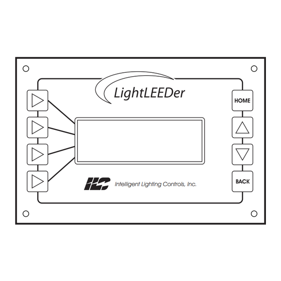
• Backlit when active • 4 selection buttons, 2 scrolling buttons, a hOMe button, and a BACK button for programming and interacting with the display. Intelligent Lighting Controls, Inc. Selection buttons (4) Scrolling buttons (2) ILC LightLEEDer Operation Manual Version 1C 3/14/17... -
Page 12: Reliant40 Lighting Control Relays
• lightsync data line devices connect directly to the local port allowing up to 64 devices per panel, and/or connect up to 254 devices on the panel network with the use of a network controller. ILC LightLEEDer Operation Manual Version 1C 3/14/17... - Page 13 Section 2 Installation LIGHTLEEDER SAT 01/01/11 04:19:44 PM EDIT NODE: 01 Intelligent Lighting Controls, Inc. ILC LightLEEDer Operation Manual Version 1C 3/14/17...
-
Page 14: Section 2 Installation 2.0 Pre-Installation Check List
2.3.5 Cable Termination and Testing ..............2.3.6 Connect Cable ..................... 2.4 Pre-Power-Up Checks....................2.5 Power-Up and Check Out.................... 2.5.1 Power-Up....................... 2.5.2 Verify Relays Operation ..................2.5.3 Clearing Memory....................2.5.4 set the Internal Clock..................ILC LightLEEDer Operation Manual Version 1C 3/14/17... -
Page 15: Wiring The Controller
Installation This section details the installation of the lightleeDer lighting controller. The proper installation of the hardware and wiring is important to make a trouble free reliable lighting control system. 2.0 Pre-Installation Check List Unpack the lighting control panel. Report any damage to the freight carrier. -
Page 16: Line And Load Wires
4 OFF 3 COM 4 COM POWER EXT +V 77013488A 24VAC CT EXTCOM 97013488 77013485A 24VAC CT POWER 77013488A 24VAC CT 97013488 High Voltage Routing Area Figure 2.2 – Class2 and HV wiring areas ILC LightLEEDer Operation Manual Version 1C 3/14/17... -
Page 17: Network Cable Installation
Data cable to either panels or lightsync devices are run in a daisy chain pattern to form a network. “T” connections are permitted with the use of a Power supply Repeater (PsR) and home-run lightsync devices may be done with a lightsync hub. ILC LightLEEDer Operation Manual Version 1C 3/14/17... -
Page 18: Cable Distances
OUT-B OUT-B Switch Station Figure 2.3 – LightLEEDer Network Example 2.3.4 Cable Distances Data and power is carried across the network cable. There are limitations how far data can be run, how many devices are on the line, and how much power is on the line. With the addition of a Power supply (Ps, adds power to the data line) or a Power supply Repeater (PsR, adds power and renews data on the data line ) data and power can be re- newed. - Page 19 A LightSync Hub (hUB) is a device that allows a home run configuration by providing RJ45 ports for up to 20 lightsync devices, supplying power and data up to 1500 feet per each port. Figure 2.4 – LightSync Network Cable Run Distance Detail ILC LightLEEDer Operation Manual Version 1C 3/14/17...
-
Page 20: Cable Termination And Testing
From the keypad/display push “edit” and scroll down to the “Clock” menu. From this part of the menu you can set the time and date, set up the daylight saving time settings, set the astronomical parameters, and view the current sunrise/sunset settings. see section 3.3 for more details. ILC LightLEEDer Operation Manual Version 1C 3/14/17... - Page 21 Section 3 Programming RELAYS INPUTS TIMERS CLOCK Intelligent Lighting Controls, Inc. ILC LightLEEDer Operation Manual Version 1C 3/14/17...
-
Page 22: Section 3 Programming 3.0 Information
3.7.6 Blink Alerts and Alarms ..................3.7.7 Configure Timed-On..................3.7.8 Test Programmed Timers ................. 3.8 Configure Relay Presets ....................3.8.1 setup Presets......................3.8.2 Capture Presets ....................3.8.3 Activate a Preset and View status..............ILC LightLEEDer Operation Manual Version 1C 3/14/17... - Page 23 3.10.1 Program a local input device to control relays........3.10.2 Program a network switch to control a relay group......3.10.3 set time and date example................3.10.4 Configure Timer example................3.10.5 Configure timers using Astro Time............ILC LightLEEDer Operation Manual Version 1C 3/14/17...
- Page 24 Programming 3.0 Information In this section you will learn how to program a lightleeDer lighting control system through the keypad. software is available on our website that simpli es the task and allows programming remotely. Programming can be accomplished through any keypad in any panel in a networked system. To access a panel other than the one you’re at, press...
-
Page 25: Clearing Memory
Yes and the memory will be cleared of all programming. Press FIRMWARe ReVIsIOn, then DEMO CLOCK: OFF RTC SOURCE: CRYS NETWORK: ENABLED CLEAR ALL MEMORY Press CleAR All MeMORY CLEAR ALL SETTINGS? Press ILC LightLEEDer Operation Manual Version 1C 3/14/17... -
Page 26: Clearing Specific Parts Of Memory
CLEAR SELECTED? g) CleAR PReseTs: Clears all presets con gurations. (Individual panels only) 8. You will be prompted to clear selected? Press 9. Press Yes and the memory will be cleared of all programming ILC LightLEEDer Operation Manual Version 1C 3/14/17... -
Page 27: Clock Settings
The default settings are start: 2nd week in March, end: 1st Press ClOCK week in november. TIME/DATE DAYLIGHT SAVINGS ASTRO CLOCK SUNRISE/SUNSET Press DAYlIghT sAVIngs CONFIG DST: ENABLED START DATE END DATE CURRENT: STD set dates, Press hOMe ILC LightLEEDer Operation Manual Version 1C 3/14/17... -
Page 28: Set Latitude/Longitude And Time Zone
NODE Press eDIT, scroll down until ClOCK appears RELAYS INPUTS TIMERS CLOCK Press ClOCK TIME/DATE DAYLIGHT SAVINGS ASTRO CLOCK SUNRISE/SUNSET Press sUnRIse/sUnseT TIMES FOR TODAY SUNRISE = 07.40 SUNSET = 16.30 Press hOMe ILC LightLEEDer Operation Manual Version 1C 3/14/17... -
Page 29: Input Setup And Configuration
Retro Hardwire Input: Input from a hardwired lightMaster, Quanta elite, or Quanta RsX system that has been retro tted with a lightleeDer controller. Note: The Echo input types emulates another device on the system. ILC LightLEEDer Operation Manual Version 1C 3/14/17... -
Page 30: Configure A Lightsync Device Input Type
TYPES A/B TYPE TIMES TOGGLE SOURCE Press TYPes A/B TYPE A DISABLED TYPE B DISABLED Press TYPe A or TYPe B TYPE A MNT ON/OFF TYPE B DISABLED Press to select device type ILC LightLEEDer Operation Manual Version 1C 3/14/17... - Page 31 If the Disabled switch input type A or B is set to this input shall blink and postpone being turned OFF. an Input Active Time the switch input will be ignored. The alert time shall be programmable from 2 to 99 ILC LightLEEDer Operation Manual Version 1C 3/14/17...
-
Page 32: How To See The Status Of A Switch/Input
TYPe to select A or B (type A is the default) INPUT IN:01.01.1 TYPES A/B TYPE TIMES TOGGLE SOURCE Press TYPe TIMes MODE: TIME OF DAY DAY: TIME: 12:00A - 12:29A TYPE: A Press DAY or TIMe, then scroll to the desired settings ILC LightLEEDer Operation Manual Version 1C 3/14/17... -
Page 33: Setup A Toggle Source
OFF input closed: Any chosen OFF input that is closed TYPE UNUSED OFF input open: Any chosen OFF input that is open Note: switch inputs must be programmed with a switch type to function scroll to the desired conditional. ILC LightLEEDer Operation Manual see table 3.3 Version 1C 3/14/17... -
Page 34: Configure Pilot Status
Preset True: The status pilot light will be illuminated when the chosen Preset is true scroll to select the desired Preset False: The status pilot light will be illuminated when pilot control the chosen Preset is false ILC LightLEEDer Operation Manual Version 1C 3/14/17... -
Page 35: Configure A Lightsync Photocell Input
600-232 2-53 12-121 70-188 700-234 3-64 13-125 80-191 800-235 4-76 14-128 90-194 900-236 5-85 15-130 100-197 1000-237 6-91 20-141 150-208 1200-238 7-97 30-157 200-216 1400-239 8-102 40-171 300-223 1600-240 9-108 50-179 400-228 1800-241 ILC LightLEEDer Operation Manual Version 1C 3/14/17... -
Page 36: Relay Configuration And Programming
8. Press lOCK to toggle between DIsABle/enABle RELAY TYPE TIMER OFF OPTION POWER-ON ACTION CONDITIONALS Press RelAY TYPe RELAY RLY:01.01 POLE: SINGLE LOCK: DISABLED Press POle or lOCK to make adjustments ILC LightLEEDer Operation Manual Version 1C 3/14/17... -
Page 37: Relay Output Timer Off Options
8. ACS OFF: each relay programmed will turn the relay OFF for 5 seconds, setting the Automatic Control switch to the OFF position 9. ACS Blink: each relay programmed will turn the relay OFF for 1 second, setting the Automatic Control switch to initiate a 5 minute delay before shutting OFF. ILC LightLEEDer Operation Manual Version 1C 3/14/17... -
Page 38: Configure Power-Up Options
RELAY TYPE TIMER OFF OPTION POWER-ON ACTION CONDITIONALS Press POWeROn ACTIOn RELAY RLY:01.01 POWER-ON ACTION NO ACTION scroll to adjust the option. see Table 3.7 Continued on next page ILC LightLEEDer Operation Manual Version 1C 3/14/17... -
Page 39: Setup Conditionals For Relays
COnDITIOn A (set condition B for your second conditional if desired) RELAY RLY:01.01 CONDITION A=UNUSED 9. Press to select the condition type CONDITION B:UNUSED LOGIC:AND Press COnDITIOn A or B ILC LightLEEDer Operation Manual Version 1C 3/14/17 Continued on next page... - Page 40 Hold Status/Force ON/OFF -Hold Status/Hold Status/Hold Status - Hold Status/Force OFF/Force ON FORCE OFF HOLD STATUS Force OFF/Force ON/Hold Status - Force OFF/Hold Status/Force ON - Force OFF/Force OFF/Force OFF PRIORITY RELEASE REVERT: NO ILC LightLEEDer Operation Manual scroll down once and Version 1C 3/14/17 press ReleAse ReVeRT to enable...
-
Page 41: Configure Relay Groups
3.6.5 Configure Relay Groups Configure Relay Groups Relays can be grouped together to make it easy to program timers RELAY STATUS and inputs. The lightleeDer has the capability of 256 groups that are RELAY OPTIONS GROUP RELAYS network-wide. INPUT MAPPING 1. -
Page 42: Relay Status And Forcing Relays On/Off
RLY:01.01 IS OFF TURN ON 7. Press TURn OFF to force the relay Off TURN OFF LOCK:OFF scroll to the desired relay to see status. Press TURn On or OFF to force the relay ILC LightLEEDer Operation Manual Version 1C 3/14/17... -
Page 43: Sweep All Relays In A Panel On And Off
Sweep all Relays in a Panel On and OFF RELAY STATUS SINGLE RELAY RELAY GROUPS SWEEP RELAYS From the RelAYs/RelAY sTATUs screen, press sWeeP RelAYs SWEEP RELAYS ALL ON ALL OFF Press All On or All OFF to sweep relays ILC LightLEEDer Operation Manual Version 1C 3/14/17... -
Page 44: Time Based Operations
Programming 3.7 Time Based Operations lightleeDer panels are capable of 128 time based actions which in- clude Time-of-Day, Astronomical scheduling, and Open-Close-Time control. Timers can turn On or OFF any relay, group of relays, or trigger any Preset. (Presets are a programmed On/OFF pattern of relays. see section 3.7 for more information). - Page 45 OPen or OPEN/CLOSE ClOse timer Press OPen/ClOse 8. Press to clear any offset programmed TIMER.001 OPEN OPN+000MIN CLOSE CLEAR OFFSET Press OPen or ClOse then scroll to the desired settings ILC LightLEEDer Operation Manual Version 1C 3/14/17...
- Page 46 Configure Timer Conditionals 5. Press COnDITIOnAls see section 3.5.6 for input conditionals TIMER TIMER.001 TIME UNUSED DAYS CONDITIONALS Press COnDITIOnAls TIMER.001 DISABLE CONDITION A=UNUSED CONDITION B=UNUSED LOGIC:AND ILC LightLEEDer Operation Manual see section 3.5.6 to setup the conditionals Version 1C 3/14/17...
-
Page 47: Timer Mapping Control
8. Press “ hOMe” to exit to the home screen TIMER TIMER.001 GROUP GROUP.001 ACTION NONE Press TIMeR and scroll to the desired timer Then press gROUP and scroll to the desired group. Then press ACTIOn and scroll to the desired action. ILC LightLEEDer Operation Manual Version 1C 3/14/17... -
Page 48: Off Hour Sweeps
Press InClUDe OFF HOURS SWEEPS 6. Press “ hOMe” to exit to the home screen RELAY RLY:01.01 INCLUDE:YES scroll to the desired relay or group and Press InClUDe ILC LightLEEDer Operation Manual Version 1C 3/14/17... -
Page 49: Program Open And Close Times
ReseT All TIMes scroll to the month and date, then press eDIT DATE: JAN/01 OPEN OP --:-- -M CLOSE CL --:-- -M CLEAR Press OPen or ClOse then ILC LightLEEDer Operation Manual scroll to the desired time Version 1C 3/14/17... -
Page 50: Blink Alerts And Alarms
Network Controller Node 00 as shown in Section 3.0) 2. Press TIMeRs 3. scroll down, then press BlInK AleRT/AlARM 4. Press DeFAUlT seTTIngs to set all blink alerts and alarms to the default ILC LightLEEDer Operation Manual Version 1C 3/14/17... -
Page 51: Configure Timed-On
BLINK ALERT/ALARMS 10. Press “ hOMe” to exit to the home screen CONFIGURE TIMED-ON TEST TIMERS Press TesT TIMeRs TEST TIMER TIMER TIMER.001 TEST scroll to the timer to be tested, then press TesT ILC LightLEEDer Operation Manual Version 1C 3/14/17... -
Page 52: Configure Relay Presets
(note: status is ACTIVATE A PRESET shown in this screen) PRESET:PRESET.001 6. Press ACTIVATe STATUS:TRUE ACTIVATE 7. Press “ hOMe” to exit to the home screen scroll to the desired preset, then press ACTIVATe ILC LightLEEDer Operation Manual Version 1C 3/14/17... -
Page 53: Controller System Functions
9. Continue until all characters have been edited 10. Press sAVe to store the programming DEFAULT PANEL NAME ILC LIGHTLEEDER 11. Press hOMe SAVE Press then scroll to the desired character ILC LightLEEDer Operation Manual Version 1C 3/14/17... - Page 54 Press eDIT 11. Continue until all characters have been edited 12. Press sAVe to store the programming DEFAULT 13. Press hOMe GROUP.001 SAVE Press then scroll to the desired character ILC LightLEEDer Operation Manual Version 1C 3/14/17...
- Page 55 SAVE 11. Continue until all characters have been edited Press then scroll 12. Press sAVe to store the programming to the desired character 13. Press hOMe ILC LightLEEDer Operation Manual Version 1C 3/14/17...
-
Page 56: Setting Up A Password
9. Continue until all characters have been edited (Be sure to record the password) CLEAR PASSWORD 10. Press sAVe to store the programming OOOOOO SAVE Press then scroll to the desired number ILC LightLEEDer Operation Manual Version 1C 3/14/17... -
Page 57: Viewing Current Firmware Revision
DIMMER DEVICES 10. Press to scroll through the test results for each scan MOTOR DEVICES 11. Press hOMe to exit Press lIghTsYnC DeVICes, DIMMeR DeVICes, or MOTOR DeVICes. scroll to see each device. ILC LightLEEDer Operation Manual Version 1C 3/14/17... -
Page 58: Backup And Restore
6. Press 7 times Press BACKUP/ResTORe DATA 7. Press DIAgnOsTICs 8. Press BACKUP/ResTORe DATA BACKUP ALL DATA RESTORE ALL DATA COMPARE ALL DATA Press BACKUP All DATA, ResTORe All DATA, or COMPARe All DATA ILC LightLEEDer Operation Manual Version 1C 3/14/17... -
Page 59: Programming Examples
IN:01.04.1 TYPES CONDITIONALS PILOT Press TYPes twice, then TYPE A P.B. ON/OFF TYPE B DISABLED Press BACK twice, then INPUT IN:01.04.2 TYPES CONDITIONALS PILOT Repeat steps 8, 9, 10 ILC LightLEEDer Operation Manual Version 1C 3/14/17 Continued on next page... - Page 60 RelAY, then DEVICE IN:01.04.1 INPUT RELAY RLY:01.05 ACTION NONE Press ACTIOn, then DEVICE IN:01.04.1 INPUT RELAY RLY:01.05 ACTION ON-OFF(H Press InPUT, then DEVICE IN:01.04.2 INPUT RELAY RLY:01.07 ACTION ON-OFF(H Follow steps 12, 13, 14 ILC LightLEEDer Operation Manual Version 1C 3/14/17...
-
Page 61: Program A Network Switch To Control A Relay Group
LS DEVICE 0A TYPE 1 BUTTON Press BACK, then press COnFIgURe InPUTs INPUT IN:00.0A.1 TYPES A/B TYPE TIMES TOGGLE SOURCE Press TYPes twice, then TYPE A P.B. ON/OFF TYPE B DISABLED ILC LightLEEDer Operation Manual Version 1C 3/14/17 Continued on next page... - Page 62 NONE Press gROUP, then DEVICE IN:00.0A.1 INPUT GROUP GROUP.003 ACTION NONE Press ACTIOn, then DEVICE IN:00.0A.1 INPUT GROUP GROUP.003 ACTION ON-OFF(H Press hOMe ILC LIGHTLEEDER 01/21/11. 09:46:54 EDIT NODE ILC LightLEEDer Operation Manual Version 1C 3/14/17 Continued on next page...
- Page 63 GROUP: GROUP.003 RELAY: RLY:01.10 INCLUDE: YES Press RelAY, then RELAY GROUPS GROUP: GROUP.003 RELAY: RLY:01.12 INCLUDE: NO Press InClUDe RELAY GROUPS GROUP: GROUP.003 RELAY: RLY:01.12 INCLUDE: YES Press hOMe ILC LightLEEDer Operation Manual Version 1C 3/14/17 Continued on next page...
- Page 64 GROUP: GROUP.003 RELAY: RLY:04.25 INCLUDE: YES Press RelAY, then RELAY GROUPS GROUP: GROUP.003 RELAY: RLY:04.25 INCLUDE: NO Press InClUDe RELAY GROUPS GROUP: GROUP.003 RELAY: RLY:04.25 ILC LightLEEDer Operation Manual INCLUDE: YES Version 1C 3/14/17 Repeat for Relay 27, Press hOMe...
-
Page 65: Set Time And Date Example
TIME 07:04:33 DATE TUE 01/04/11 Press TIMe, MInUTe then to set, then press seT. SET TIME/DATE TIME 11:15:00 DATE WED 01/05/11 Press DATe then MONTH 01/04/11 DATE YEAR Follow steps 9-12, press hOMe ILC LightLEEDer Operation Manual Version 1C 3/14/17... -
Page 66: Configure Timer Example
MINUTE Press BACK, then DAYs TIMER TIMER.001 DAY OF WEEK CALENDAR-DAILY Press DAY OF WeeK TIMER.001 SUN IS ENABLED ENABLE DISABLE Press DIsABle TIMER.001 SUN IS DISABLED ENABLE ILC LightLEEDer Operation Manual DISABLE Version 1C 3/14/17 Continued on next page... - Page 67 TIMER.001 RELAY RLY:01.06 ACTION Press ACTIOn TIMER TIMER.001 RELAY RLY:01.06 ACTION Repeat for relays 01.07 and 01.08. Follow steps 9-12 to program relays 01.06, 7 and 8 to turn OFF with Timer 002 ILC LightLEEDer Operation Manual Version 1C 3/14/17...
-
Page 68: Configure Timers Using Astro Time
LONGITUDE TIME ZONE SEY BY CITY Press seT BY CITY, then AZ, PHOENIX LAT:033 LON:112 TIME ZONE:MOUNTAIN Press seT, then BACK four times ILC LIGHTLEEDER NC 01/21/11. 09:46:54 EDIT ILC LightLEEDer Operation Manual Version 1C 3/14/17 Continued on next page... - Page 69 Press BACK, then TIMER TIMER.002 TIME 06:30:00 DAYS WED 01/05/11 CONDITIONALS Press TIMe, then AsTRO TIMER.002 SUNRISE +000MIN SUNSET CLEAR OFFSET Press sUnRIse TIMER.002 TIME SR +000MIN DAYS _MTWTF_ ILC LightLEEDer Operation Manual CONDITIONALS Version 1C 3/14/17 Continued on next page...
- Page 70 TIMER.001 RELAY RLY:01.06 ACTION Press ACTIOn TIMER TIMER.001 RELAY RLY:01.06 ACTION Repeat for relays 01.07 and 01.08. Follow steps 9-12 to program relays 01.06, 7 and 8 to turn OFF with Timer 002 ILC LightLEEDer Operation Manual Version 1C 3/14/17...
- Page 71 Section 4 Appendix RELAYS INPUTS TIMERS CLOCK Intelligent Lighting Controls, Inc. ILC LightLEEDer Operation Manual Version 1C 3/14/17...
-
Page 72: Section 4 Appendix Appendix A: Dimmer Module
Appendix J: lightsync Input Board and Photocell Controller ...... Appendix K: lightsync hub and Occupancy sensor ........Appendix l: networked Room Controllers and expansion Panels ..... Appendix M: lightleeDer emergency Ul 924 lighting Control ....ILC LightLEEDer Operation Manual Version 1C 3/14/17... - Page 73 LightSync Dimming Module A = Direct B = Source 100mA Maximum per module C = Sink (default) Warning: To prevent electrocution and/or damage to hardware, measure voltage from energized ballast prior to terminating. ILC LightLEEDer Operation Manual Version 1C 3/14/17...
- Page 74 DMX COnTROl (Track up to 512 channels) POWER-ON LEVEL Dimmer Status: CONTROL OPTIONS 8. Press until sTATUs/COnTROl appears DMX CONTROL STATUS CONTROL 9. Press sTATUs/COnTROl (Raise or lower set Points to make equal)) 10. Press hOMe to exit ILC LightLEEDer Operation Manual Version 1C 3/14/17...
- Page 75 IN-1 IN-2 IN-2 OUT-A OUT-A Motor Power Supply OUT-B OUT-B Input DC Voltage Motor Control Output MOTOR 2 MOTOR 4 IN-1 IN-1 IN-2 IN-2 OUT-A OUT-A OUT-B OUT-B 4.50” LightSync Motor Controller Module ILC LightLEEDer Operation Manual Version 1C 3/14/17...
- Page 76 “On” time CONTROL 01 required ACTION DEVICE 15. Press hOMe to exit INPUT Press ACTIOn then RUn TIMe CONTROL 01 ACTION: RUN-POS RUN TIME=LATCH Press hOMe ILC LightLEEDer Operation Manual Version 1C 3/14/17 Continued on next page...
- Page 77 Run Negative: When contact is made on the input the motor output will go negative with an adjustable output of .1 second to 10 seconds in .1 second increments, 10 to 300 second increments, or latched. ILC LightLEEDer Operation Manual Version 1C 3/14/17...
-
Page 78: Appendix C: Dtmf Module (Panel Level)
FCC Part 68 Information lightleeDer Voice Prompted DTMF Telephone Control modules comply with Part 68 of the FCC rules and the require- ments adopted by the ACTA. On the back plate near the RJ 11 jack of this equipment is a label that contains, among other information, the FCC registration number and ringer equivalence (Ren) for this equipment. -
Page 79: Appendix D: Dmx Module (Panel Level)
DMX Module (panel level) The lightleeDer DMX512 Control Module provides control of relays and 0 – 10V dimming devices. Any channel from the DMX controller can be mapped to control any relay or group of relays On or OFF in the panel. The On and Off set points are adjustable from 1 to 100% and relays may be locked-on or locked-off. - Page 80 BACnet Module (panel level) BACnet is an open protocol developed by AshRAe for building automation and control systems. lightleeDer BACnet MsTP or IP modules give you direct control of the panel. With the panel module, commands can be sent to the panel to force relays On and OFF, force relays On and OFF with a timer option (blink, double blink, hID delay, Alarm On, Alarm OFF, Pulse On, and Pulse OFF), monitor relay status, monitor input status, and enable/disable inputs.
-
Page 81: Appendix F: Modbus® Module (Panel Level)
Modbus protocol is an open protocol developed by gould-Modicon to integrate industrial PlC’s, sensing devices, and other control devices. lightleeDer Modbus modules can interface either AsCII or RTU type of communications with Baud rates from 4800 to 38,400 and parity of none, even, or Odd. With the panel module, commands can be sent to the panel to force relays On and OFF, force relays On and OFF with a timer option (blink, double blink, hID delay, Alarm On, Alarm OFF, Pulse On, and Pulse OFF), monitor relay status, monitor input status, and enable/disable inputs. - Page 82 Ribbon connector to panel ADD-ON MODULE 1 TYPE:PROTOCESSOR EDIT Press and select 77013517A 97013517 the PROTOCessOR option 2.0” LightLEEDer LonWorks Control Module (Panel level) For a LightLEEDer LonWorks point map go to: http://ilc-usa.com/product_detail.php?pid=32 ILC LightLEEDer Operation Manual Version 1C 3/14/17...
-
Page 83: Appendix H: N2 Module (Panel Level)
The host system can then poll the status of the lightMaster Controller inputs and outputs and issue On/OFF commands to the lightleeDer ’s relay outputs. With the panel module, commands can be sent to the panel to force relays On and OFF, force relays On and OFF with a timer option (blink, double blink, hID delay, Alarm On, Alarm OFF, Pulse On, and Pulse OFF), monitor relay status, monitor input status, and enable/disable inputs. - Page 84 Back Lexan ® cover Node address settings (Each switch must be set to a Location unique Light LED 4.125” 4.875” node address) Durable buttons Status LEDs 1.437” RJ-45 Data connectors G2 LightSync Switch ILC LightLEEDer Operation Manual Version 1C 3/14/17...
- Page 85 Standard 1/2” conduit thread. Outdoor 1.3” 1. 1 8” 2.5” 5.6” Adhesive backing .375” Indoor 1.375” .625” 2.5” 1.0” Controller 3.25” Remote Mounting Enclosure Sensors LightSync Photocell Controller ILC LightLEEDer Operation Manual Version 1C 3/14/17...
- Page 86 1 2 V A C 20- RJ-45 Data connectors to LightSync devices 77013442 REV A In OUT 97013442 REV 24 VAC out 120/277 VAC In Voltage Divider Transformer Network data IN/OUT LightSync Hub in enclosure ILC LightLEEDer Operation Manual Version 1C 3/14/17...
- Page 87 From the panel controller (called an expansion Controller with no local relay output modules installed), the relays in Room Controllers all appear to be residing locally in the panel. With the panel connected to the lightleeDer network, these remote relays can be controlled just like any relay in panels on the network.
- Page 88 Appendix l LL-2RC, -4RC, -4X Mapping Matrix ILC LightLEEDer Operation Manual Version 1C 3/14/17...
- Page 89 Relays in these remote panels are programmed as if they were installed in the panel. lightleeDer-2RC and -4RC panels have lightsync device addresses built into each unit for 2 - 6 button lightsync push button switches (these addresses include the hardwire occupancy sensor inputs), 2 lightsync photocells, and 1 lightsync dimmer.
- Page 90 The lightleeDer emergency Ul 924 lighting controller provides emergency bypass operation for IlC’s R40 relays. The lightleeDer panel will be provided with Ul 924 Relay Bypass Output Modules that will override the relays On when normal power is lost to the panel. An optional Phase Monitoring Module can be added to the panel to monitor two or three phase power, when eM load relays are on more than one power phase of the emergency system.
- Page 91 Appendix M LightLEEDer UL 924 Emergency Relay Bypass Output Module (RBOM) details: The RBOM mounts in the same location as a standard Relay Output Module, as shown on lighting controller detail 1.3, and uses the same mounting screws and ribbon connections to the R40 relays.
- Page 92 If the entire panel is operating emergency powered loads, normal power must be used to power the transformer and LightLEEDer CPU. If the panel controls a combination of normal and emergency loads, the standard layout would have the left side or bottom half of the panel with the emergency load relays. Separation between EM and normal power relays is provided using the steel High Voltage Dividers (HVD) placed between relay sections.
- Page 93 AC power system. This is used to ensure that when any of the three phases drops, the lightleeDer emergency relay panel will react as an emergency event. The power from the transformer is run to the PMM, and then to the power distribution card.
- Page 94 Figure 3 - Phase Monitoring Module detail Phase Monitoring Module Configuration and Wiring: The lightleeDer panel provided with optional Phase Monitoring Module will require eld wiring the phase “B” and phase “C” un-switched normal power to the PMM. 1. Verify the PMM is installed and power from the transformer is connected to “FROM TRX 24VAC CT”...
- Page 95 Power panel Emergency Relay Control Panel Power panel 3-Phase monitering of normal power UL1008 EM Distribution Transfer Emergency Controll Switch System Emergency Generator EM Control system Figure 5 - Power Configuration Example Riser ILC LightLEEDer Operation Manual Version 1C 3/14/17...
- Page 96 For more information, please contact: INTELLIGENT LIGHTING CONTROLS, INC. 5229 Edina Industrial Boulevard Minneapolis. Minnesota 55439 Phone 952 829 1900 • 1-800-922-8004 FAX 952 829 1901 • www.ilc-usa.com...
Need help?
Do you have a question about the LightLEEDer and is the answer not in the manual?
Questions and answers