
Related Manuals for Allen-Bradley 1794-VHSC


Summary of Contents for Allen-Bradley 1794-VHSC
- Page 1 –1 Allen-Bradley User Very High Speed Counter Manual Module (Cat. No. 1794-VHSC) Allen-Bradley Spares...
- Page 2 FLEX I/O, DeviceNet, DeviceNetManager, and RediSTATION are trademarks of Allen-Bradley Company, Inc. PLC, PLC–2, PLC–3, and PLC–5 are registered trademarks of Allen-Bradley Company, Inc. All other brand and product names are trademarks or registered trademarks of their respective companies.
- Page 3 Audience You must be able to program and operate an Allen-Bradley programmable controller (PLC) to make efficient use of this module. We assume that you know how to do this in this manual. If you do...
- Page 4 ControlNet messages to the adapter. The PLC receives module status information through ControlNet messages from the adapter. Related Publications For a list of publications with information on Allen-Bradley programmable controller products, consult our publication index SD499. Publication 1794-6.5.10 – December 1998...
-
Page 5: Table Of Contents
..2–9 Wiring connections for the 1794-VHSC High Speed Counter Module ....... . . - Page 6 4–5 Input Data Behavior upon Module Removal ....4–5 High Speed Counter Module (1794-VHSC) Image Table Mapping 4–6 Troubleshoot the Very High Chapter 5 Speed Counter Module What This Chapter Contains .
-
Page 7: Overview Of The Very High
Module Description The VHSC module performs high speed counting for industrial applications. The module is an intelligent I/O module that interfaces signals with any Allen-Bradley programmable controller that has ControlNet capability. The VHSC module, once configured for its intended purpose, can continue to operate without flexbus power. -
Page 8: Operation In Encoder Or Counter Mode
PLC is switched to PROGRAM mode pulse width modulation (PWM) mode is available The 1794-VHSC module operates in the following modes: counter mode – encoder X1 mode... - Page 9 (0-16,777,215). The counter mode accepts only one phase feedback. This relationship is shown in figure 1.1. Allen-Bradley Spares Publication 1794-6.5.10 – December 1998...
-
Page 10: Encoder Mode
Overview of the Very High Speed Counter Module Figure 1.1 Block Diagram of Counter Mode Input A Input B Z (Store Count) Input Z Single Phase Pulse Generator (Gate/Reset) 1794-VHSC Count Up Count Down A Input B Input – Count Outputs updated continuously Encoder Mode... - Page 11 Figure 1.2 Phase Relationship for Forward or Reverse Directions High Speed Counter Module Input A Input B Z (Store Count) Input Z Quadrature Encoder (Gate/Reset) 1794-VHSC Forward Rotation Reverse Rotation CCW Encoder Rotation CW Encoder Rotation A Input B Input Count Count...
-
Page 12: Preset Value
1–6 Overview of the Very High Speed Counter Module Preset Value Each of the 2 counters has one preset value associated with it. In the encoder or counter modes, the preset value represents a reference point (or count) from which the module begins counting. The module can count either up or down from the preset value. - Page 13 Read Data file. The stored count remains in the Read Data file until it is overwritten with new data. Figure 1.5 Store-Reset/Wait/Start Counter has stopped counting Start counting Stop count, store from zero and reset to zero 10682-I Allen-Bradley Spares Publication 1794-6.5.10 – December 1998...
-
Page 14: Operation In Period/Rate Mode
(MSW) for channel 1. Select the period/rate mode by setting the appropriate bits in word 0 of the configuration block. 1794-VHSC modules count the total number of pulses occurring at the Z (gate/reset) pin. This function is frequency-limited to 200Hz X the scaler value. - Page 15 B (not used) Input B Z (gate/reset) Input Z Single Phase Pulse Generator scaler 5MHz Clock 1794-VHSC Incoming pulse train at Z (gate/reset terminal) 5MHz internal clock Frequency and Outputs Accumulated Count updated here Assumes symmetrical pulse, 50% duty cycle, so period = sample time on X 2 (on and off)
- Page 16 1–10 Overview of the Very High Speed Counter Module Table 1.A Relationship Between Sampled Pulses and Input Frequency Input Frequency at Z Sampled Pulses for 1/2 Cycle (Gate/Reset) of Z (Gate/Reset) Pulse Terminal in Hz 1.25M 500K 250K 125K 12.5K 1KHz 2.5K 2KHz...
-
Page 17: Continuous/Rate Mode
5MHz counts later. 1794-VHSC modules count the total number of pulses occurring at the Z (gate/reset) terminal. This function is frequency-limited to 200Hz X the scaler value. This total count is returned in input file words 4 (LSW) and 5 (MSW) for channel 0 and 6 (LSW) and 7 (MSW) for channel 1. -
Page 18: Operation In Rate Measurement Mode
Input B Z (not used) Input Z Encoder/Pulse Generator (Gate/Reset) Time base 1794-VHSC A Input (pulse) Internal Sampling Gate Accumulated Count Frequency calculated, outputs updated here If sample period is 50ms, and count = 3, then frequency = 3/50ms = 60Hz Example: In figure 1.9, three counts have been accumulated during the... -
Page 19: Pulse Width Modulation
By setting bits in the configuration block, you can assign the outputs on the module to any of the various counter windows. You can assign any output to any count window with no restrictions. Allen-Bradley Spares Publication 1794-6.5.10 – December 1998... -
Page 20: Operation Of Outputs
1–14 Overview of the Very High Speed Counter Module Operation of Outputs When the outputs for the VHSC module are enabled and assigned to a counter window they operate in an ON-OFF fashion. For example, assume that the module were programmed to turn ON an output when a count value of 2000 was reached. -
Page 21: What The High Speed Counter Module Does
2. External devices generate input signals that are transmitted to the module. 3. The module converts these signals into binary format, and stores these values and controls their output until the adapter requests Allen-Bradley Spares their transfer. Publication 1794-6.5.10 – December 1998... -
Page 22: Chapter Summary
1–16 Overview of the Very High Speed Counter Module 4. The adapter transfers the data over the flexbus. 5. The adapter and module determine that the transfer was made without error and inputs values are within a specified range. 6. ControlNet transfers the data to the PLC data table. Chapter Summary In this chapter you learned how your module operates, and how your module communicates with the programmable controller. -
Page 23: What This Chapter Contains
Module Indicators ....2–14 Before You Install Your Before installing your 1794-VHSC very high speed counter module: Input Module You need to: As described under:... -
Page 24: Low Voltage Directive
Programmable Controllers, Part 2 – Equipment Requirements and Tests. For specific information required by EN 61131-2, see the appropriate sections in this publication, as well as the following Allen-Bradley publications: Industrial Automation Wiring and Grounding Guidelines For Noise Immunity, publication 1770-4.1... -
Page 25: Wiring The Terminal Base Units (1794-Tb3G Shown)
Note: Use this configuration if using any digital output 24V dc modules that could couple transients to the 24V supply. VHSC Module wiring separate from digital wiring. Wiring when total current draw is greater than 10A Allen-Bradley Spares Publication 1794-6.5.10 – December 1998... -
Page 26: Installing The Module
2–4 How to Install Your Very High Speed Counter Module Installing the Module Installation of the very high speed counter module consists of: mounting the terminal base unit installing the VHSC module into the terminal base unit installing the connecting wiring to the terminal base unit If you are installing your module into a terminal base unit that is already installed, proceed to “Mounting the High Speed Counter Module on the Terminal Base”... - Page 27 Gently push the flexbus connector into the side of the adapter to complete the backplane connection. 5. Repeat the above steps to install the next terminal base. Allen-Bradley Spares Publication 1794-6.5.10 – December 1998...
-
Page 28: Panel/Wall Mounting
2–6 How to Install Your Very High Speed Counter Module Panel/Wall Mounting Installation on a wall or panel consists of: laying out the drilling points on the wall or panel drilling the pilot holes for the mounting screws mounting the adapter mounting plate installing the terminal base units and securing them to the wall or panel If you are installing your module into a terminal base unit that is... - Page 29 7. Secure to the wall with two #6 self-tapping screws. 8. Repeat for each remaining terminal base unit. Note: The adapter is capable of addressing eight modules. Do not exceed a maximum of eight terminal base units in your system. Allen-Bradley Spares Publication 1794-6.5.10 – December 1998...
-
Page 30: Mounting The High Speed Counter Module On The Terminal Base Unit
How to Install Your Very High Speed Counter Module Mounting the High Speed Counter Module on the Terminal Base Unit The 1794-VHSC module mounts on a 1794-TB3G or TB3GS terminal base unit. 1. Rotate the keyswitch (1) on the terminal base unit (2) clockwise to position 1 as required for this module. -
Page 31: Connecting Wiring For The High Speed Counter Module
Module Compatible terminal base units are: Module 1794-TB3G 1794-TB3GS 1794-VHSC 1794-TB3G 1794-TB3GS 0 1 2 3 4 5 6 9 10 11 12 13 14 15 18 19 20 21 22 23... - Page 32 2–10 How to Install Your Very High Speed Counter Module 2. Connect individual output wiring to terminals 6, 7 and 14, 15 on the 0–15 row (A) and terminals 23, 24 and 31, 32 on the 16–32 row (B) on the terminal base unit. Connect output return wiring for channels 0, 1, 2, and 3 to terminals 23, 24 31 and 32 respectively.
- Page 33 –V = negative isolated power connection (1A max.) +24V dc = 24V dc terminal base power for module COM = return for +24V dc terminal base power for module Chassis Gnd = chassis ground for input or output cable shields Allen-Bradley Spares Publication 1794-6.5.10 – December 1998...
-
Page 34: Wiring Connections For The 1794-Vhsc High Speed Counter Module
2–12 How to Install Your Very High Speed Counter Module Wiring connections for the 1794-VHSC High Speed Counter Module Terminal Base Units Incremental 1794–TB3G, –TB3GS Encoder Encoder Input nput Channel 0 Channel 1 +24V Inputs Input A Input A Input B... -
Page 35: Example Of Quadrature Encoder Wiring To A 1794-Tb3G Terminal Base Unit
Quadrature Encoder (Gate/Reset) (ex. 845H–SJ__24DRY__ ) Mechanical Switch 10 11 12 13 14 0 –15 16–33 34–51 1794-TB3G 24V Base Power – Solenoid Attention: Keep exposed area of inner conductor as short as possible. Allen-Bradley Spares Publication 1794-6.5.10 – December 1998... -
Page 36: Module Indicators
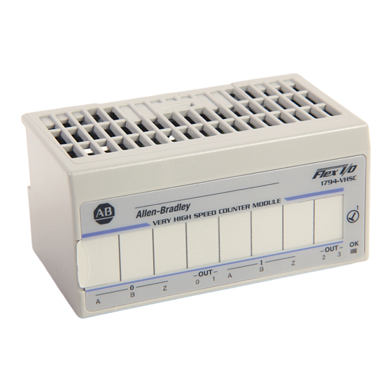
The high speed counter module has one red/green status indicator (OK) that is on when power is applied to the module and one yellow indicator for each input and output. Allen-Bradley 1794–VHSC VERY HIGH SPEED COUNTER MODULE A = Power/status indicator – indicates power applied to module and status of module. -
Page 37: Allen-Bradley Spares
(active high or active low) is present at one of the Input terminals. Chapter Summary In this chapter, we told you how to install your input module in an existing programmable controller system and how to wire to the terminal base units. Allen-Bradley Spares Publication 1794-6.5.10 – December 1998... - Page 38 2–16 How to Install Your Very High Speed Counter Module Publication 1794-6.5.10 – December 1998...
- Page 39 To initiate communication between the very high speed counter module and your PLC processor, you must use RSLogix 5 software. Refer to the RSLogix software manuals for information on communicating with this 1794-VHSC very high speed counter module. Allen-Bradley Spares...
-
Page 40: Programming Your Very High Speed Counter Module
3–2 Programming Your Very High Speed Counter Module Publication 1794-6.5.10 – December 1998... -
Page 41: Input, Output And Configuration Files For The
Inputs Inputs Inputs Read Read Words Status Status Status ControlNet Adapter Network Outputs Outputs Outputs Write Write Words Configuration Configuration Configuration Slot 0 Slot 1 Slot 7 Data is exchanged scheduled (when mapped) or unscheduled (using Allen-Bradley Spares CIO instructions). -
Page 42: Scheduled Data-Transfer
4–2 Input, Output and Configuration Files for the Very High Speed Counter on ControlNet Scheduled Data-Transfer Scheduled data transfer: is continuous is asynchronous to the ladder-logic program scan occurs at the actual rate displayed in the Actual Packet Interval field on the programming software ControlNet I/O mapping (monitor) screen Unscheduled Data-Transfer Unscheduled operations include:... -
Page 43: I/O Structure
I/O Module Fault Bits Bit: 10 through 15 Not Used I/O State Bit Created by PLC–5 controller Node Address Changed Bit The adapter input status word bit descriptions are shown in the following table. Allen-Bradley Spares Publication 1794-6.5.10 – December 1998... -
Page 44: Safe State Data
4–4 Input, Output and Configuration Files for the Very High Speed Counter on ControlNet Bit Description Explanation This bit is set (1) when an error is detected in slot position 0. This bit is set (1) when an error is detected in slot position 1. This bit is set (1) when an error is detected in slot position 2. -
Page 45: Communication Fault Behavior
I/O module input data sent by the adapter upon module removal is configurable. The adapter can: reset the module output data to zero (reset) leave the module output data in the last state before module removal (hold last state) Allen-Bradley Spares Publication 1794-6.5.10 – December 1998... -
Page 46: High Speed Counter Module (1794-Vhsc) Image Table Mapping
4–6 Input, Output and Configuration Files for the Very High Speed Counter on ControlNet High Speed Counter Module (1794-VHSC) Image Table Mapping Module Image Channel 0 Current Count (least significant word) Channel 0 Current Count (most significant word) ControlNet Files... - Page 47 Second Counter 1st Off Value (most significant word) Second Counter 2nd On Value (least significant word) Second Counter 2nd On Value (most significant word) Second Counter 2nd Off Value (least significant word) Second Counter 2nd Off Value (most significant word) Allen-Bradley Spares Publication 1794-6.5.10 – December 1998...
- Page 48 4–8 Input, Output and Configuration Files for the Very High Speed Counter on ControlNet Configuration File Size (continued) Second Counter 3rd On Value (least significant word) Second Counter 3rd On Value (most significant word) 56 Words Second Counter 3rd Off Value (least significant word) Second Counter 3rd Off Value (most significant word) Second Counter 4th On Value (least significant word) Second Counter 4th On Value (most significant word)
- Page 49 X gate interval. The time to detect a zero frequency is determined by the sample interval (example: time base = 0.100s, gate interval = 3 is 300ms to determine ZF). Allen-Bradley Spares Publication 1794-6.5.10 – December 1998...
- Page 50 4–10 Input, Output and Configuration Files for the Very High Speed Counter on ControlNet Input Word Definition Stored/data count bit (C0, C1) for Channel 1 – This count cycles thru 00, 01, 10, 11, 00... Each time the stored/accumulated count words are updated, 06, 07 C(0,1) is incremented.
- Page 51 When LC = 0, the module clears its OE bit at a loss of flexbus power. Set this bit as appropriate in the safe state word, since a communication fault Allen-Bradley Spares occurs after adapter power is lost. Publication 1794-6.5.10 – December 1998...
- Page 52 4–12 Input, Output and Configuration Files for the Very High Speed Counter on ControlNet Output Word Definition Not used – set to 0. Output 2 Force output bit (FO) – When set to 1, output is turned on if OE is 08 (10) 1.
- Page 53 Mode 1 – store/continue Mode 2 – store/wait/resume Mode 3 – store;reset/wait/start Mode 4 – store;reset/start Bit 15 (17) Invert the Z signal – 0 = Z not inverted; 1 = Z inverted Allen-Bradley Spares Publication 1794-6.5.10 – December 1998...
- Page 54 4–14 Input, Output and Configuration Files for the Very High Speed Counter on ControlNet Configuration Definition Word Filter Selection – Only 1 filter selection can be chosen at a time. Frequency = 50% duty cycle. Bits 00–03 Counter 0 Bits 08–11 Counter 1 (10–13) (13)
- Page 55 S2 = Tie output to second counter 2nd window S3 = Tie output to second counter 3rd window S4 = Tie output to second counter 4th window Bits 08–15 Set to 0. (10–17) Allen-Bradley Spares Publication 1794-6.5.10 – December 1998...
- Page 56 4–16 Input, Output and Configuration Files for the Very High Speed Counter on ControlNet Configuration Definition Word Counter On and Off – These words program each of the 4 counter’s (first and second counter) on and off values. The first compare window for each counter is used in PWM, and when programmed for PWM, the associated compare window should remain at 0.
-
Page 57: What This Chapter Contains
Input A not active Yellow Input B active Input B not active Yellow Input Z active Input Z not active OUT 0, 1, 2, 3 Yellow Output is on Individual output is off Allen-Bradley Spares Publication 1794-6.5.10 – December 1998... -
Page 58: Diagnostic Codes Returned By The Module
5–2 Troubleshoot the Very High Speed Counter Module Indicator Indication Explanation Red (solid) Hardware diagnostic error, TF set to 1 and module/channel status contains error code. Hardware runtime failure (i.e. watchdog timeout), module communication ceases. Red (flashing) Module is configuring hardware, NR is set to 1. Module in test mode (bits 15–8 of counter control word are non–zero), TF set to 1 Red (flashing) -
Page 59: What's Next
EEPROM test failed Word 8 Programmable Gate Array loading failed All other combinations not used What’s Next To find out more about the VHSC module: See appendix A Specifications specifications on the 1794-VHSC module Allen-Bradley Spares Publication 1794-6.5.10 – December 1998... - Page 60 5–4 Troubleshoot the Very High Speed Counter Module Publication 1794-6.5.10 – December 1998...
-
Page 61: Specifications
Appendix pecifications Specifications – 1794-VHSC Very High Speed Counter Module Input Specifications Number of Counters Number of Inputs per Counter 2 groups of A/A, B/B, and Z/Z pairs with 5V dc or 15-24V dc terminations Input Voltage 5V dc or 15-24V dc (determined on terminal... - Page 62 A–2 Specifications Specifications – 1794-VHSC Very High Speed Counter Module Output Specifications Number of Outputs 2 isolated groups of 2 (0.5A max. @ 5V dc; 1.0A max. @ 12–24V dc) Output Control Outputs can be tied to 8 compare windows Output Supply Voltage Range 5-7V dc;...
- Page 63 Specifications A–3 Specifications – 1794-VHSC Very High Speed Counter Module General Specifications Module Location Cat. No. 1794-TB3G or -TB3GS Terminal Base Dimensions Inches 1.8H x 3.7W x 2.1D (Millimeters) (45.7 x 94.0 x 53.3) External dc Power Refer to 24V Derating Curve below...
- Page 64 A–4 Specifications Publication 1794-6.5 10 – December 1998...
- Page 65 Index Numbers 1794-VHSC, troubleshoot, 5–1 frequency input module, how it works, 1–15 adapter input status word, 4–3 gate reset input, 1–6 CE compliance, 2–1 I/O, ControlNet unscheduled non-discrete I/O data CIOs. See ControlNet I/O Transfer transfer, 4–2 instructions unscheduled operations compatible terminal bases, 2–9...
- Page 66 1–13 rate measurement mode, 1–12 wall/panel mounting, 2–6 removing and replacing, under power wiring, methods of, 2–3 (RIUP), 2–9 wiring connections, 2–9 rollover value, 1–6 1794-VHSC, 2–12 sample period, 1–12 Publicati0on 1794-6.5.10 – December 1998...
- Page 67 Sequence What is not in the right order? Other Comments Use back for more comments. Your Name Location/Phone Return to: Marketing Communications, Allen-Bradley Co., 1 Allen-Bradley Drive, Mayfield Hts., OH 44124-6118 Phone: (216)646-3176 FAX: (216)646-4320 Allen-Bradley Spares Publication ICCG-5.21-May 1990...
- Page 68 Other Comments PLEASE FOLD HERE NO POSTAGE NECESSARY IF MAILED IN THE UNITED STATES BUSINESS REPLY MAIL FIRST-CLASS MAIL PERMIT NO. 18235 CLEVELAND OH POSTAGE WILL BE PAID BY THE ADDRESSEE TECHNICAL COMMUNICATION 1 ALLEN BRADLEY DR MAYFIELD HEIGHTS OH 44124-9705 Publication...
- Page 69 Philippines Poland Portugal Puerto Rico Qatar Romania Russia–CIS Saudi Arabia Singapore Slovakia Slovenia South Africa, Republic Spain Sweden Switzerland Taiwan Thailand Turkey United Arab Emirates United Kingdom United States Uruguay Venezuela Yugoslavia Allen-Bradley Headquarters, 1201 South Second Street, Milwaukee, WI 53204 USA, Tel: (1) 414 382-2000 Fax: (1) 414 382-4444 Allen-Bradley Spares Publication 1794-6.5.10 –...
Need help?
Do you have a question about the 1794-VHSC and is the answer not in the manual?
Questions and answers