
Related Manuals for Skee Ball Hot Shot


Summary of Contents for Skee Ball Hot Shot
- Page 1 Hot Shot Basketball Installation and Operation Manual 990445 02 Oct 15; rev 23+ Skee Ball, Inc., 121 Liberty Lane, Chalfont, PA 18914 Voice: (215) 997-8900 Fax: (215) 997-8982...
-
Page 2: Table Of Contents
Table of Contents WARNINGS........................4 SPECIFICATIONS ......................5 ASSEMBLY SEQUENCE ....................6 Power–Up Sequence......................24 Game Overview ....................... 24 Idle Display (Attract Mode) ................... 24 Coins ..........................24 Game Play ........................24 Scoring ..........................24 End Of Game ........................24 Credits .......................... - Page 3 Game Time and Score Displays ................. 29 Opto-Sensors ....................... 29 SD Card (contains certain sound data) ..............30 Game Options / How to program .................. 31 “Discount Games” Programming Examples: ............... 33 FOR YOUR RECORDS… ..................... 34 TICKET DISPENSER ....................35 Basic operation of ticket dispenser model DL1275H ...........
-
Page 4: Warnings
WARNINGS Read this manual thoroughly before assembling your game. Failure to follow the instructions could cause damage to your game and void your warranty. In addition, the manual explains the game in detail and the options you have so that you and your players can enjoy the game to its fullest. -
Page 5: Specifications
SPECIFICATIONS HOT SHOT BASKETBALL GAME all TBD Height xx in Width xx in Length xx in Weight xxx lbs. Uncrated xxx lbs. Crated Power Maximums: 115 VAC, x.0 AMPS xxx WATTS Power Averages: 115 VAC, x.0 AMPS xxx WATTS... -
Page 6: Assembly Sequence
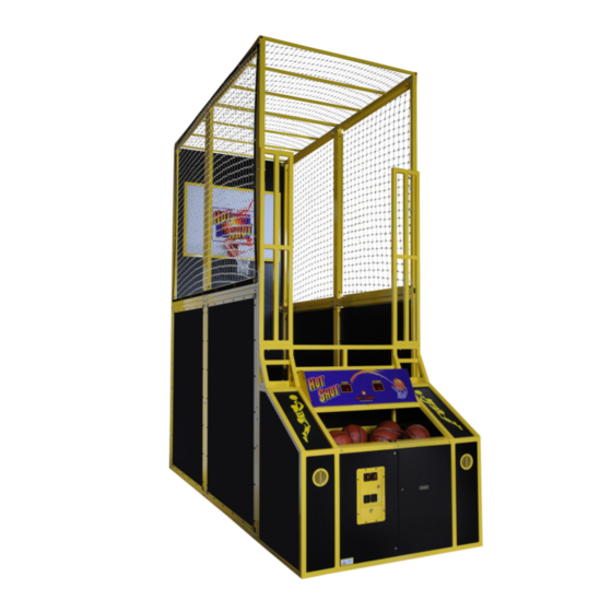
ASSEMBLY SEQUENCE Assembly of Hot Shot will require 2 or 3 strong people, tools, and about 4 hours of time. Here is a photo of the finished assembly of the game:... - Page 7 Here is an isometric drawing of the finished assembly of the game:...
- Page 8 Step 1: Assemble the lower back panel with both the lower right and left rear panels: Qty 4) 3/8 16 x 1” bolt Qty 8) 3/8 washer Qty 4) 3/8 16 nylock nut...
- Page 9 NOTE: Tighten the 1” bolts via the hole in the back of the game.
- Page 10 Step 2: Tip the assembly on its back, and attach the upper back panel to the lower back panel: Qty 2) 3/8 16 x 2 3/4” bolt Qty 4) 3/8 washer Qty 2) 3/8 16 nylock nut...
- Page 12 Step 3: Stand this assembly upright and attach the rear playfield floor: Qty 4) 3/8 16 x 3” bolt Qty 4) specially modified 3/8 washer Qty 4) 3/8 washer Qty 4) 3/8 16 nylock nut NOTES: Insert the 3” bolts through the side holes, but do not tighten. Hang the rear floor onto bolts (underneath.)
- Page 13 Use the specially modified washers on the inside of the bolt. The flat of the specially modified washer avoids a clearance problem.
- Page 15 Step 4: Attach the lower left and right front panels, then the front playfield floor: 3/8 16 x 3” bolt 3/8 16 x 2 3/4” bolt specially modified 3/8 washer Qty 12) 3/8 washer 3/8 16 nylock nut...
- Page 17 Step 5: Attach the upper left and right rear side nets, then the upper left and right front side nets: 3/8 16 x 3” bolt 3/8 16 x 2 3/4” bolt 3/8 16 x 1” bolt Qty 36) 3/8 washer Qty 18) 3/8 16 nylock nut...
- Page 18 NOTE: Do not tighten the 3” bolt’s nylock nuts (to prepare for the mounting of the top canopies in Step 7.)
- Page 19 Step 6: Attach the backboard: Qty 4) 3/8 washer Qty 4) 3/8 16 nylock nut...
- Page 20 Step 7: Attach the rear top canopy then the front top canopy: NOTE: Hardware for this step was applied in Step 5 (3” loose bolts in 8 locations.) Also: Use assemblers on ladders on each side to hoist each canopy, pass one side to the opposite assembler, then lower the slots in each canopy onto the loose 3”...
- Page 21 Step 8: Attach the triangular ball diverters using pre-made holes in the ramp floor. Qty 4) 1/4 20 2” cap screw Qty 4) 1/4 20 nylock nut...
- Page 22 Step 9: Attach the console then the left and right front vertical ball guards: #14 self-drillers Qty 10) 3/8 16 x 2 3/4” bolt Qty 20) 3/8 washer Qty 10) 3/8 16 nylock nut 1/4 20 x 3 1/2” bolt 1/4 washer 1/4 20 nylock nut...
- Page 23 NOTES: Slide the console into place. Continued… From the inside of the game (carefully climb in via the front doors), C-clamp the console to the game until flush. This solves any slight racking problems. Use self-drillers and attach the bottom brackets to the game. Attach the upper brackets to the game with the 2 3/4”...
-
Page 24: Power-Up Sequence
Power–Up Sequence The game will perform some internal checks and show the software revision number on the 4-digit display (such as: “r 07”). If “attract audio” is enabled, the game will then begin playing an audio attract snippet. Game Overview This game is designed to be universal by offering an array of programming capabilities in hopes that you, the game operator, will have all of the settings regarding tickets, coins, length of game, etc., that you need, available for your location. - Page 25 The game will dispense tickets to the player according to the many different operator adjustable options. (See “Game Options - Tickets”) In the event the game is out of tickets, the game will inform the player to call an attendant. The attendant must correct the malfunction and or reload the tickets. Then the game will automatically dispense the tickets owed to the player.
-
Page 26: Major Components
Return at the front of the game. It is used to programs all game options, and counts tickets and coins Programming Display The Hot Shot game uses the TIME and SCORE displays (on the game’s console) to assist during options programming. Power Supply The Power Supply (P/N 800758-5) is located in the electronics area, below the ball return at the front of the game. -
Page 27: Ball Release Actuator
Ball Release Actuator The Ball Release Actuator (P/N 800853-3) raises and lowers the ball release ramp that captures the balls when a game is not in play. The actuator is located approximately in the center of the game on the bottom floor, and is accessible by removing the back panel. -
Page 28: Ticket Dispenser
Ticket Dispenser The Ticket Dispenser (P/N 800142-2) is located on the right Coin Door. This device dispenses tickets to the player. The Ticket Tray (P/N 8000552-1) is attached to the door directly below the Ticket Mech. Coin Mechanisms (Coin Mechs) / Cash Box The Coin Mechs (P/N 800671-23) and Coin Box (P/N 387020-1) are located in the left front of the game. -
Page 29: Game Time And Score Displays
Game Time and Score Displays These are the dual two-digit displays that report time remaining (in seconds) for the current game (“TIME”), and the current game’s score (“SCORE”) (in points, where 1 basket always scores 2 or 3 points). These displays are also used during Options Programming. -
Page 30: Sd Card (Contains Certain Sound Data)
SD Card (contains certain sound data) The SD card on the main controller board must be properly inserted for the game to work correctly. -
Page 31: Game Options / How To Program
Printed here is a copy of the options list (and programming help) as mounted behind the Coin Door: SkeeBall, Inc. - Hot Shot Basketball Game Use the "RESET" button to sequence through the options. Use the "AUX" buttons to sequence through the option values. - Page 32 3 points per basket during end-game 3-point period (26-Sep-2014; rev 22+) Hot Shot has been designed to give the operator a great deal of flexibility in operating the game. Rather than employing a dipswitch system, Hot Shot employs a system using the RESET &...
-
Page 33: Discount Games" Programming Examples
To access, view and/or change the game options, the operator must use all three of the buttons located behind the coin door. Each button has a specific function and location as outlined below: LOCATION LABEL FUNCTION Cycle BACKWARD through all Left AUX 1 option choices. -
Page 34: For Your Records
FOR YOUR RECORDS… P1: Reset Defaults Setting P1 to a ‘1’ and then pressing RESET will COPY (reload) all of the factory defaults into all of the options. Option: Purpose Current Increment Default In Units Of P2: Game Time _________ seconds P3: Attract Audio Period _________... -
Page 35: Ticket Dispenser
TICKET DISPENSER Basic operation of ticket dispenser model DL1275H When the control unit calls for a ticket to be issued, the motor in the dispenser is turned on. When a ticket is dispensed, the opto beam breaker senses a notch in the ticket and sends back a signal to the control unit. -
Page 36: Conditions That Could Cause The Ticket Error To Be Announced
Ticket Guide Spring The ticket guide spring insures that the notches in the tickets pass through the Opto Beam Breaker Sensor. To increase tension, loosen screw and move other spring up. This changes the tension of the inner spring. Tickets should be snug between spring and side plate but not deformed by excess tension. -
Page 37: Parts Reference
Parts Reference... -
Page 38: General Troubleshooting
GENERAL TROUBLESHOOTING CAUTION: High voltage is present in some areas of the game (power supply, SCR, solenoid, etc.). Unplug line cord before performing any troubleshooting. PROBLEM RECOMMENDATION Game halts after power-up The controller is looking for its SD memory card, but cannot find it. -
Page 39: Returned Components
Returned Components Should your product need servicing, please have the following information ready prior to contacting Skee-Ball, Inc. Model # of the Unit Serial # of the Unit Serial # of the Part (i.e. – Main Processor Board) if applicable. Most of this information can be found on the serial number tag attached usually to rear of the product. -
Page 40: Warranty
WARRANTY Your new HOT SHOT game is warranted to the original end user for a period of 90 days for mechanical components and 1 year for electronics from date of first use. Your sales receipt determines date of first use. -
Page 41: Wire Schematic
Wire Schematic See attached.
Need help?
Do you have a question about the Hot Shot and is the answer not in the manual?
Questions and answers