jbc DME-1A Instruction Manual
Four-tool control unit
Hide thumbs
Also See for DME-1A:
- Instruction manual (13 pages) ,
- Instruction manual (17 pages) ,
- Instruction manual (17 pages)
Table of Contents
Advertisement
Quick Links
Advertisement
Table of Contents

Related Manuals for jbc DME-1A


Summary of Contents for jbc DME-1A
- Page 1 www.jbctools.com INSTRUCTION MANUAL Four-Tool Control Unit Ref. DME-A...
-
Page 2: Packing List
The following items should be included: Four-Tool Power Cord ....1 unit Manual ......1 unit Control Unit ....1 unit Ref. 0010569 (230V) Ref. 0012837 Ref. DME-1A (120V) 0013671 (100V/120V) DME-2A (230V) DME-9A (100V) w w w.jbctools.com INSTRUCTION MANUAL Four-Tool Control Unit Ref. - Page 3 w w w.jbctools.com Connections Work simultaneously with up to 4 tools and 1 module + 1 pedal for each tool (Peripherals). DME Control Unit Stands Equipotential connection RJ45 connector for LAN USB-B connector Peripherals RJ12 connector for Robot Power Socket and fuse RJ12 connector for PSE and Robot system Compatibility...
-
Page 4: Operation
Operation The JBC Exclusive Heating System Our revolutionary technology is able to recover tip temperature extremely quickly. It means the user can work at a lower temperature and improve the quality of soldering. The tip temperature is further reduced thanks to the Sleep and Hibernation modes which increase a tip life by 5. -
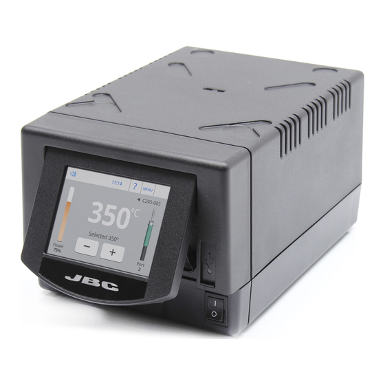
Page 5: Work Screen
w w w.jbctools.com Work Screen The DME-A offers an intuitive user interface which provides quick access to the station parameters. Original PIN: 0105 Station Information Help for each parameter Station Lock Cartridge 17:14 MENU in use PIN required for unlocking Introduce the C245-003 reference for... -
Page 6: Menu Screen
Menu Screen Select any option and press the station information button to display the data of each parameter. Adjust tool settings for each port Join station ports with modules and pedals 17:14 Personalize the station: Registers total Station name, PIN and partial hours activation, Screen for each port: work,... -
Page 7: System Notifications
w w w.jbctools.com Cartridge Adjustment Insert the cartridge and the station will recognize its characteristics (size and shape) to provide more accurate temperature readings. 17:14 Tools T245 - port 3 After connecting the tool, introduce Cartridge Adjust C245-003 the last 3 reference numbers of the cartridge. -
Page 8: Process Analysis
Process analysis Optimize your production after analysing the information provided by the graphics. By pressing Graphics in the Utilities MENU, temperature and power figures in real time are displayed for each port. This helps you decide how to adjust your process or which tip to use to obtain the best quality soldering. - Page 9 Soldering Network Remotely manage and monitor your stations from a PC. 1. Download the JBC Manager software and the user manual from www.jbctools.com/manager.html 2. Connect the stations via USB-B or LAN (RJ45) and the PC will automatically detect them.
- Page 10 Multiply x6 the capacity of your DME Centralize control of 5 PSE Power Supply Units in a single DME and work with as many as 24 tools simultaneously. 1. Connect the DME to the PSE Power Supply Units via the PS socket (RJ12). 2.
- Page 11 Control Unit RS-232 connection Update the station software 1. Download the JBC Update File from 2. Insert the USB flash drive to the station. www.jbctools.com/software.html and The icon is diplayed while updating. save it on a USB flash drive. Preferably one with no other files.
-
Page 12: Maintenance
If necessary use a tool to lever it off. return it to the station. - Replace any defective or damaged pieces. Use original JBC spare parts only. - Repairs should only be performed by a JBC authorized technical service. - Page 13 w w w.jbctools.com Safety It is imperative to follow safety guidelines to prevent electric shock, injury, fire or explosion. - Do not use the units for any purpose other than soldering or rework. Incorrect use may cause fire. - The power cord must be plugged into approved bases. Make sure that it is properly grounded before use.
-
Page 14: Specifications
Specifications DME-1A 120V 50/60Hz. Input fuse: 6A. Output: 23.5V DME-2A 230V 50/60Hz. Input fuse: 3.15A. Output: 23.5V DME-9A 100V 50/60Hz. Input fuse: 8A. Output: 23.5V - Weight: 4,573 Kg (10.08 lb) - Dimensions: 148 x 120 x 232 mm (5.83 x 4.72 x 9.13 in) -
Page 15: Exploded View
w w w.jbctools.com Exploded View... - Page 16 Warranty JBC’s 2 year warranty covers this equipment against all manufacturing defects, including the replacement of defective parts and labour. Warranty does not cover product wear or misuse. In order for the warranty to be valid, equipment must be returned, postage paid, to the dealer where it was purchased.
Need help?
Do you have a question about the DME-1A and is the answer not in the manual?
Questions and answers