
Related Manuals for Shure UC


Summary of Contents for Shure UC
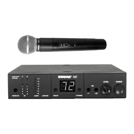
- Page 1 E2005, Shure Incorporated 27D8614 (Rev. 6) UC Wireless System User Guide UC WIRELESS SYSTEM User Guide Printed in U.S.A.
-
Page 2: Table Of Contents
ENGLISH QUICK SETUP GUIDE FOR THE SHURE UC WIRELESS SYSTEM UC4 Receiver Setup ................ -
Page 3: Quick Setup Guide For The Shure Uc Wireless System
ENGLISH QUICK SETUP GUIDE FOR THE SHURE UC WIRELESS SYSTEM UC4 Receiver Setup 1. Plug the dc power supply into the power connector on the back of the receiver. Connect the other end of the power supply into an electrical outlet. (This power supply is for indoor use only.) 2. -
Page 4: System Description
Logic In/Out Terminal (On Receiver). Provides logic interface with external devices. Preconfigured Group/Channel and Frequency Setup. Ensures frequency compatibility and simplifies instal- lation of multiple UC systems. A “Group” is a preconfigured set of frequencies or channels that do not interfere with one another. -
Page 5: Uc1 Transmitter Features And Controls
LEMO connectors are available as an option. 5. Remote Mute Switch Input Connector. When used with the optional Shure UA101 Remote Mute Switch, this 3.5 mm connector lets you remotely mute the body pack during a performance. -
Page 6: Uc2 Transmitter Features And Controls
ENGLISH UC2 HAND–HELD TRANSMITTER FEATURES AND CONTROLS UC2 TRANSMITTER FEATURES AND CONTROLS 1. Grille. Protects the microphone cartridge and helps reduce breath sounds and wind noise. The grilles for the vari- ous microphone heads differ in appearance. 2. Power Indicator/Battery Fuel Gauge. When the UC2 is turned on, one of three LEDs will glow, indicating that power is on and the amount of battery life remaining. -
Page 7: Uc4 Receiver Controls And Connectors
12.Power Connector. Accepts power from the supplied AC adapter, or from any filtered 15–18 Vdc (600 mA minimum) supply. It also accepts the dc power cord from a Shure UA845 Antenna Distribution System. 13.Low Z (balanced) Output Connector. XLR connector provides balanced low–impedance mic level or line level output. -
Page 8: Receiver Cable Connections
ENGLISH RECEIVER CABLE CONNECTIONS 1. Connect the receiver output to the mixer or amplifier input, using a standard audio cable with a female 3–pin XLR connector or 1/4” phone plug. Refer to Figure 5. 2. Connect the AC power adapter to the POWER jack on the rear panel of the receiver. 3. -
Page 9: Changing The Uc1 Transmitter Battery
ENGLISH Changing the UC1 Transmitter Battery 1. Make sure the transmitter power ON/OFF switch is in the OFF position. 2. Open the transmitter battery compartment by squeezing the two tabs on either side of the transmitter. Then flip the battery cover down. Refer to Figure 6. 3. -
Page 10: Operating The Uc1 Body-Pack System
4. If you are using an instrument adapter cable, plug it into the instrument. 5. If you are using a WM98 condenser mic, install it onto the Shure A98KCS Horn Mount assembly attached to the bell of your horn. Refer to Figure 9. -
Page 11: Operating The Uc2 Hand-Held System
LEDs on the receiver flickers during the loudest sounds. NOTE: For guitar applications, the minimum setting (full counterclockwise) is recommended. If you are using the Shure WH10TQG headset, rotate the gain control to the fully clockwise position. Then, if necessary, rotate it back slightly. -
Page 12: Changing The Transmitter Group/Channel Settings
ENGLISH Changing the Transmitter Group/Channel Settings 1. Turn the transmitter off and open the battery compartment to expose the GROUP and CHANNEL switches. Refer to Figure12 below. 2. Using the supplied screwdriver, rotate the GROUP switch until the desired setting is reached. Then rotate the CHANNEL switch until the the desired setting is reached. -
Page 13: Changing Receiver Settings
Group setting and the character on the right represents the Channel setting. Groups are preconfigured sets of frequencies or channels that work well together. A complete list of compatible Groups and Channels is included in the separate UC Wireless Frequency Compatibility Guide. Changing the Receiver Group Setting To advance the receiver Group setting, rotate the Group switch clockwise, using the supplied screwdriver. -
Page 14: Adjusting The Equalizer Setting
ENGLISH Adjusting the Equalizer Setting The UC4 receiver incorporates a two band equalizer to help adjust the sound of the wireless system to match that of other wired and wireless products in an installation. See Figure 17. ADJUSTING THE UC4 RECEIVER EQUALIZER SETTING Adjusting the Low–Cut Filter (High Pass) The low–cut (or high–pass) filter allows all frequencies above its cutoff point to pass from filter input to filter output without attenuation, while frequencies below its cutoff point are attenuated. -
Page 15: Table Mounting
ENGLISH RECEIVER MOUNTING Table Mounting To mount a receiver on a table or other horizontal surface, attach the four adhesive bumpers to the bottom corners of the receiver and place the receiver on the mounting surface. See Figure 20. Rack Mounting a Single Receiver To mount a single receiver in an audio equipment rack, select the single rack mounting kit supplied with the system and proceed as follows: 1. -
Page 16: Rack Mounting Two Receivers Side By Side
UC4 RECEIVER 1 (TOP VIEW) FRONT BRACKET EQUIPMENT RACK NOTE: Shure recommends using the optional UA220 Passive Antenna Splitter/Combiner to front mount antennas when two receivers are installed side by side. LINK BARS LINK BARS RACK MOUNTING TWO UC4 RECEIVERS FIGURE 22 –... -
Page 17: Receiver Antenna Installation
FRONT MOUNTED ANTENNA CABLE CONNECTIONS NOTE: Shure recommends connecting the bulkhead adapter and antenna cables before mounting the receiver in a rack. Once the receiver is in the rack, it is more difficult to install the bulkhead adapters and antenna cables. -
Page 18: Remote Antenna Installation
4. Connect Shure UA820A 1/2 wave antennas to the end of the antenna cables (adapter required). 5. Mount the antennas using the Shure UA500 mounting brackets. For best RF performance, do not use the supplied 1/4 wave antennas when remoting antennas. Use UA820A 1/2 wave antennas. -
Page 19: Logic Connection Specifications
GATE 4 OVERRIDE 1 OVERRIDE 3 OVERRIDE 5 TYPICAL UC4 CONNECTIONS TO SCM810 MIXER LOGIC CONNECTOR NOTE: For more information on logic functions, please contact the Shure Applications Department. Logic Level Typical Applications Low (0V) Drives a remote LED. High (+5 V) -
Page 20: Tips For Achieving Optimum Performance
Some common problems and their solutions are identified in the table below. If you are unable to solve a problem, contact your dealer or the Shure Service Department at 1-800-516-2525 (7:30 am to 4:00 pm, Central Standard Time). In Europe, call 49-7131-72140; other international users call Shure in the U.S.A. at 847-600-2000. -
Page 21: Specifications
At its option Shure will repair or replace the defective product and promptly return it to you, or refund the purchase price. - Page 22 TABLE 1 Country Code Code de Pays Lander–Kurzel Codigo de Pais Codice del Paese All Other Countries Tous les autres pays Alle anderen Länder Demás países Tutti gli altri Paesi *Please contact your national authority for information on available legal frequencies for your area and legal use of the equipment. *Se mettre en rapport avec les autorités compétentes pour obtenir les informations sur les fréquences autorisées disponibles localement et sur l’utilisation autorisée du matériel.
- Page 23 – 102 –...
- Page 24 United States, Canada, Latin America, Caribbean: 5800 W. Touhy Avenue, Niles, IL 60714-4608, U.S.A. Phone: 847-600-2000 U.S. Fax: 847-600-1212 Int’l Fax: 847-600-6446 Europe, Middle East, Africa: Shure Europe GmbH, Phone: 49-7131-72140 Fax: 49-7131-721414 Asia, Pacific: Shure Asia Limited, Phone: 852-2893-4290 Fax: 852-2893-4055...
Need help?
Do you have a question about the UC and is the answer not in the manual?
Questions and answers